Language selection

Search

Patent 2212023 Summary

Third-party information liability

Some of the information on this Web page has been provided by external sources. The Government of Canada is not responsible for the accuracy, reliability or currency of the information supplied by external sources. Users wishing to rely upon this information should consult directly with the source of the information. Content provided by external sources is not subject to official languages, privacy and accessibility requirements.

Claims and Abstract availability

Any discrepancies in the text and image of the Claims and Abstract are due to differing posting times. Text of the Claims and Abstract are posted:

  • At the time the application is open to public inspection;
  • At the time of issue of the patent (grant).
(12) Patent: (11) CA 2212023
(54) English Title: ADJUSTING DEVICE FOR A SCREEN OF A COMPUTER
(54) French Title: DISPOSITIF D'AJUSTEMENT D'UN ECRAN D'ORDINATEUR
Status: Expired and beyond the Period of Reversal
Bibliographic Data
Abstracts

English Abstract


An adjusting device for a screen of a computer
includes a keyboard and a screen combined together with
the adjusting device for adjusting the position of the
screen from the keyboard and a sloping angle of the
screen to the keyboard to suit to different size of a
user. The device includes two support bars pivotally
connected between the screen and two bottom bars fitting
and movable in the bottom of the keyboard in a preset
distance from the keyboard. Then the dimensions of the
keyboard to sit on a table may be increased to stabilize
the computer securely. Further, the angle of the screen
to the keyboard can be adjusted by pivotal connection of
the support bars with the screen and also with the
bottom bars.


French Abstract

Dispositif d'ajustement d'écran d'ordinateur. Ce dernier est équipé d'un clavier et d'un écran, associés tous deux au dispositif d'ajustement pour que celui-ci ajuste la position et l'angle d'inclinaison de l'écran par rapport au clavier en les adaptant à la taille de l'utilisateur. Ce dispositif repose sur deux barres de soutien pivotantes, disposées entre l'écran et deux barres inférieures conçues pour s'emboîter et se déplacer sous le clavier, à une distance prédéterminée du clavier. On peut alors augmenter les dimensions du clavier pour l'installer sur une table en donnant une bonne stabilité à l'ordinateur. Il est également possible d'ajuster l'angle de l'écran par rapport au clavier à l'aide de barres de soutien pivotantes, disposées entre l'écran et les barres inférieures.

Claims

Note: Claims are shown in the official language in which they were submitted.

-8-
WHAT IS CLAIMED IS:
1. An adjusting device for a screen of a computer comprising:
a keyboard having a latch respectively at two - right and left - sides of
a front side, a guide slot in a bottom of an elongate recess provided
respectively in
two sides of a bottom of said keyboard, and a battery chamber formed in one
side for
containing a battery as a power for said computer;
a screen having a lateral bar respectively at two opposite - right and
left - sides of a front side to engage with said latches of said keyboard, a
recess
respectively in two sides in an upper surface, a support bar having its upper
end
pivotally connected with an upper end of each said recess for said support bar
to rest
therein, each said support bar having its lower end pivotally connected with a
vertical
side wall of each one of two bottom bars, a lateral plate connected between
said two
bottom bars to move together, each said bottom bar having a guide screw fixed
at an
inner end, each said guide screw fitting and able to move in each said guide
slot of
said keyboard.
2. The adjusting device for a screen of a computer as claimed in
claim 1, wherein said keyboard and said screen respectively have a grip
pivotally
fixed on a front side, and a curved recess in a bottom surface of said
keyboard and
an upper side of said screen for each said grip to rest in case of putting
away said
computer.

3. The adjusting device for a screen of a computer
as claimed in Claim 1, wherein an elongate bar is fixed
on a rear side of said keyboard for a lower end of said
screen to sit thereon in case of said screen swung open
for use.
-9-

Description

Note: Descriptions are shown in the official language in which they were submitted.


CA 02212023 1997-07-31
ADJUSTING DEVICE FOR A SCREEN OF A COMPUTER
BACKGROUND OF THE INVENTION
This invention concerns an adjusting device for a
screen of a computer, particularly combining a keyboard
and a screen with the adjusting device, enabling the
screen pulled back and forth by two bottom bars moved
out of and in the keyboard to increase dimensions of the
keyboard sitting on a table so that the computer may be
sit more stably on the table. And at the same time, the
screen is pivotally connected with two support bars so
that the screen may be adjusted in its angle to the key-
board.
Conventional computers, especially having a small
size as shown in Fig. 7, are made portable to be carried
out. They generally have a keyboard and a screen con-
nected pivotally with each other so that the screen may
be swung up for use from a collapsed position. However,
the dimensions of the keyboard is the contact dimensions
to sit on a table. When the screen is swung up to stand
sloping to rearward, the gravitational center will move
rearward, and if the contact dimensions of the keyboard
with the table is not enough to support the screen, the
screen with the keyboard or the computer may fall back,
and may be broken if worse. And chances are that a user
has to adjust sitting pose so as to look the screen
better, moving his/her body, resulting in fatigue of the
body in case of long use.
1

CA 02212023 1999-11-03
-2-
SUMMARY OF THE INVENTION
The purpose of the invention is to offer an adjusting device for a screen
of a computer for adjusting the distance between the screen and a keyboard to
increase dimensions for the keyboard to sit on a table so as to securing the
computer
on the table without possibility of falling backward in case of the screen
swung open
for use. Further the screen may be adjusted also in its angle to the keyboard.
The feature of the adjusting device of the invention is two support bars
pivotally connected with the screen and the support bars also pivotally
connected at
its lower ends with two vertical wall of two bottom bars provided to fit in
and able to
move out of a bottom of the keyboard guided by two guide screws fixed with an
inner
end of the two bottom bars connected with a lateral plate to move at the same
time
when the screen is pushed backward of forward relative to the keyboard.
According to an aspect of the invention, there is provided an adjusting
device for a screen of a computer comprising: a keyboard having a latch
respectively
at two - right and left - sides of a front side, a guide slot in a bottom of
an elongate
recess provided respectively in two sides of a bottom of said keyboard, and a
battery
chamber formed in one side for containing a battery as a power for said
computer; a
screen having a lateral bar respectively at two opposite - right and left -
sides of a
front side to engage with said latches of said keyboard, a recess respectively
in two
sides in an upper surface, a support bar

CA 02212023 1999-11-03
-2a-
having its upper end pivotally connected with an upper end of each said recess
for
said support bar to rest therein, each said support bar having its lower end
pivotally
connected with a vertical side wall of each bottom bar, a lateral plate
connected
between said two bottom bar to move together, each said bottom bar having a
guide
screw fixed at an inner end, each said guide screw fitting and able to move in
each
said guide slot of said keyboard.
The keyboard and the screen respectively may have a grip pivotally
fixed on a front side, and a curved recess in a bottom surface of said
keyboard and
an upper side of said screen for each said grip to rest in case of putting
away said
computer.
The elongate bar may be fixed on a rear side of said keyboard for a
lower end of said screen to sit thereon in case of said screen swung open for
use.
BRIEF DESCRIPTION OF DRAWINGS
Figure 1 is a perspective view of a computer with an adjusting device
for a screen in the present invention;
Figure 2 is a perspective view of the computer with a grip pulled out for
carrying in the present invention;
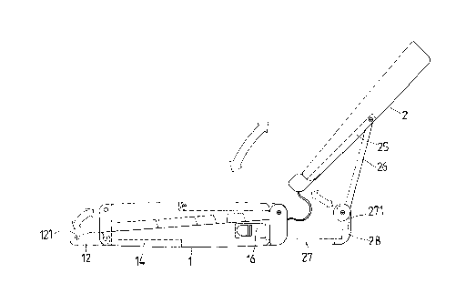
Figure 3 is a side view of the computer with a screen swung out for use
in the present invention;

CA 02212023 1997-07-31
Figure 4 is a perspective view of the computer
with the screen swung out for use in the present inven-
tion;
Figure 5 is a partial perspective view of the
screen being moved rearward from a keyboard of the com-
peter in the present invention;
Figure 6 is a side view of the screen swung out
and placed on the keyboard With its lower end in the
present invention; and,
Figure 7 is a perspective view of a conventional
computer.
DETAILED DESCRIPTION OF THE PREFERRED EMODIEMNT
A preferred embodiment of a computer with an ad-
justing device for a screen in the present invention, as
shown in Figs. 1, 2 and 3, includes a keyboard 1 and a
screen 2.
The keyboard 1 has a grip 11 pivotally connected
with a front side, a latch 12 fixed respectively on two
sides of the grip.11 on the front side and having an
engage groove 121 in an inner side to engage with a la-
teral bar 23 respectively on two opposite sides of a
front side of the screen 2. Further the keyboard 1 has a
curved recess 24 in a lower surface for the grip 11 to
fit therein in case of not for carrying. The keyboard l
also has an elongate recess 14 respectively in two sides
of the bottom for a bottom bar 17 of the screen 2 to fit
and move back and forth therein, and a guide slot 141 in
bottom side f the recess 14 for a guide screw 272 fixed
3

CA 02212023 1997-07-31
on a front end of each bottom bar 27 to fit and move
back and forth therein. Further, on a side of the key-
board 1 is formed a battery chamber 16 for containing
therein a battery as a power source of the computer.
The screen 2 has a display surface 21 on an inner
side, a grip 22 pivotally connected with a front side, a
lateral bar 23 respectively fixed at both sides of the
grip 22 for each of the two latches 12, 12 of the key-
board 1 to engage so as to lock the screen 2 with the
keyboard 1 in case the computer is not to be used. The
screen further has a curved recess 24 in a front portion
of an upper surface for receiving the grip 22 therein in
case of the grip 22 unused. The curved recess 24 is
shaped as the same as that 24 of the keyboard 1. Fur-
then, the screen 2 has a recess 25 respectively in two
sides of the upper surface, and a support bar 26 having
an upper end pivotally connected with an upper end of
each recess 24, in which the support bar may lie therein
in case of the screen 2 collapsed on the keyboard 1. The
lower end of each support bar 26 is pivotally and pro-
perly tightly connected with a vertical wall 271 at an
outer end of each of two bottom bar 27 connected with a
lateral plate 28. A front end of each bottom bar 27 is
fixed with a guide screw 271 fitted and move in each
guide slot 131 of the keyboard 1 so that the screen may
be moved rearward to any point in the same distance as
the length of the guide slots 131, 131.
When the computer is not used, the screen 2 is
4

CA 02212023 1997-07-31
collapsed by pushing it down from a swung-out position
on the keyboard 1 to a collapsed position, with the
latches 12, 12 locking the lateral bars 23, 23 to keep
the screen 2 in the collapsed position. And the grips 12
and 22 are respectively pushed in the recesses 24, 24 of
the keyboard 1 and the screen 2, as shown in Fig. 1.
In case that the computer is to be carried out,
the grips 12 and 22 are pulled out of the recesses 24
and held in a hand, as shown in Fig 2.
If the computer is to be used, the latches 12, 12
are first snapped open, disengaged from the lateral bars
23, 23 and freeing the screen 2, which is then swung
upward to the swung position wherein the screen 2 stands
a little sloped rearward as shown in Fig. 4. Then the
dimensions of the keyboard 1 sitting on a table may be
adjusted, and the sloping angle of the screen may ad-
justed as well.
The dimensions of the computer sitting on a table
can be adjusted by changing the distance between the
keyboard 1 and the screen 2, as shown in Fig. S. Chang
ing the distance is effected by the guide slots 141, 141
in the recesses 14, 14 of the keyboard 1 and the guide
screws 271, 271 of the bottom bars 27, 27. If the screen
2 is pushed backward, it can move straight back by the
guide screws 271 moving back in the guide slots 141, 141
with the bottom bars 27, 27 also moved back to lengthen
the distance between the keyboard 1 and the screen 2. In
addition, the bottom bars 27, 27, the lateral plate 28
are on the same level with the bottom of the keyboard 1,
5

CA 02212023 1997-07-31
so the bottom bars 27, 27 and the lateral plate 28 help
in stabilizing the keyboard 1 on the table.
As for adjusting the sloping angle of the screen
2, it may be effected by tightness of pivotal connec
tion between the support bars 26, 26 and the vertical
side walls 271, 271 of the bottom bars 27, 27. Firstly,
the support bars 26, 26 are pulled to a proper angle
relative to the keyboard 1, and then the screen 2 is
move relative to the support bars 26, 26 pivotally con-
connected with the screen 2. Therefore, a user can
adjust the screen 2 in its position and its angle to the
keyboard 1 to suit to user's height to see the screen
clearly and easily.
Further, an elongate bar 15 is provided on a rear
side of the keyboard 1 for a lower end of the screen 2
to sit thereon in case of the screen 2 is in the swung
open position, as shown in Fig. 6.
As can be seen from the aforesaid description,
this invention has the following advantages conventional
computers do not have.
1. Dimensions of a computer sitting on a table can
be increased by pulling the screen back to stabilize the
computer on the table, by means of the guide slots of
the recess of the keyboard and the guide screws of the
bottom bars fitting and moving back and forth in the
guide slots.
2. The screen can be adjusted in its angle rela-
tive to the keyboard by pivotal connection of the bottom
6

CA 02212023 1997-07-31
bars with the support bars, and pivotal connection of
the screen with the support bars, for a user to easily
operate the computer.
While the preferred embodiment of the invention
has been described above, it will be recognize and un
derstood that various modifications may be made therein
and the appended claims are intended to cover all such
modifications which may fall within the spirit and scope
of the invention.
15
25
7

Representative Drawing
A single figure which represents the drawing illustrating the invention.
Administrative Status

2024-08-01:As part of the Next Generation Patents (NGP) transition, the Canadian Patents Database (CPD) now contains a more detailed Event History, which replicates the Event Log of our new back-office solution.

Please note that "Inactive:" events refers to events no longer in use in our new back-office solution.

For a clearer understanding of the status of the application/patent presented on this page, the site Disclaimer , as well as the definitions for Patent , Event History , Maintenance Fee  and Payment History  should be consulted.

Event History

Description Date
Time Limit for Reversal Expired 2001-07-31
Letter Sent 2000-07-31
Grant by Issuance 2000-07-18
Inactive: Cover page published 2000-07-17
Inactive: Final fee received 2000-04-18
Pre-grant 2000-04-18
Notice of Allowance is Issued 2000-02-18
Letter Sent 2000-02-18
Notice of Allowance is Issued 2000-02-18
Inactive: Approved for allowance (AFA) 2000-01-28
Amendment Received - Voluntary Amendment 1999-11-03
Inactive: S.30(2) Rules - Examiner requisition 1999-08-04
Application Published (Open to Public Inspection) 1999-01-31
Inactive: IPC assigned 1997-10-24
Classification Modified 1997-10-24
Inactive: First IPC assigned 1997-10-24
Inactive: Filing certificate - No RFE (English) 1997-10-09
Filing Requirements Determined Compliant 1997-10-09
Application Received - Regular National 1997-10-08
Request for Examination Requirements Determined Compliant 1997-07-31
All Requirements for Examination Determined Compliant 1997-07-31

Abandonment History

There is no abandonment history.

Maintenance Fee

The last payment was received on 1999-07-02

Note : If the full payment has not been received on or before the date indicated, a further fee may be required which may be one of the following

  • the reinstatement fee;
  • the late payment fee; or
  • additional fee to reverse deemed expiry.

Please refer to the CIPO Patent Fees web page to see all current fee amounts.

Fee History

Fee Type Anniversary Year Due Date Paid Date
Request for examination - small 1997-07-31
Application fee - small 1997-07-31
MF (application, 2nd anniv.) - small 02 1999-08-02 1999-07-02
Final fee - small 2000-04-18
Owners on Record

Note: Records showing the ownership history in alphabetical order.

Current Owners on Record
JUNG-CHUAN YEN
Past Owners on Record
None
Past Owners that do not appear in the "Owners on Record" listing will appear in other documentation within the application.
Documents

To view selected files, please enter reCAPTCHA code :


To view images, click a link in the Document Description column. To download the documents, select one or more checkboxes in the first column and then click the "Download Selected in PDF format (Zip Archive)" or the "Download Selected as Single PDF" button.

List of published and non-published patent-specific documents on the CPD .

If you have any difficulty accessing content, you can call the Client Service Centre at 1-866-997-1936 or send them an e-mail at CIPO Client Service Centre.


Document
Description 
Date
(yyyy-mm-dd) 
Number of pages   Size of Image (KB) 
Abstract 1997-07-31 1 21
Description 1997-07-31 7 220
Claims 1997-07-31 2 41
Drawings 1997-07-31 7 229
Cover Page 2000-06-22 1 45
Cover Page 1999-02-25 1 45
Description 1999-11-03 8 260
Claims 1999-11-03 2 43
Representative drawing 1999-02-25 1 6
Representative drawing 2000-06-22 1 6
Filing Certificate (English) 1997-10-09 1 164
Request for evidence or missing transfer 1998-08-03 1 115
Reminder of maintenance fee due 1999-04-01 1 111
Commissioner's Notice - Application Found Allowable 2000-02-18 1 166
Maintenance Fee Notice 2000-08-28 1 178
Correspondence 2000-04-18 1 34