Language selection

Search

Patent 2212284 Summary

Third-party information liability

Some of the information on this Web page has been provided by external sources. The Government of Canada is not responsible for the accuracy, reliability or currency of the information supplied by external sources. Users wishing to rely upon this information should consult directly with the source of the information. Content provided by external sources is not subject to official languages, privacy and accessibility requirements.

Claims and Abstract availability

Any discrepancies in the text and image of the Claims and Abstract are due to differing posting times. Text of the Claims and Abstract are posted:

  • At the time the application is open to public inspection;
  • At the time of issue of the patent (grant).
(12) Patent Application: (11) CA 2212284
(54) English Title: ANISOTROPIC REINFORCED RIBBON-CAST BLANKET FOR EXTENDED NIP PRESS
(54) French Title: TOILE RAINUREE A RENFORT ANISOTROPIQUE POUR PRESSE A PINCE ALLONGEE
Status: Deemed Abandoned and Beyond the Period of Reinstatement - Pending Response to Notice of Disregarded Communication
Bibliographic Data
(51) International Patent Classification (IPC):
  • D21F 3/02 (2006.01)
  • D03D 15/242 (2021.01)
  • D06N 3/14 (2006.01)
  • D06N 7/06 (2006.01)
(72) Inventors :
  • MCCARTEN, PAUL (United States of America)
  • SLAGOWSKI, EUGENE L. (United States of America)
(73) Owners :
  • BELOIT TECHNOLOGIES, INC.
(71) Applicants :
  • BELOIT TECHNOLOGIES, INC. (United States of America)
(74) Agent: SMART & BIGGAR LP
(74) Associate agent:
(45) Issued:
(22) Filed Date: 1997-08-05
(41) Open to Public Inspection: 1998-02-13
Examination requested: 1997-08-05
Availability of licence: N/A
Dedicated to the Public: N/A
(25) Language of filing: English

Patent Cooperation Treaty (PCT): No

(30) Application Priority Data:
Application No. Country/Territory Date
08/696,248 (United States of America) 1996-08-13

Abstracts

English Abstract


A conventional blanket material, preferably a woven fabric or
scrim, is formed into a loop of the desired dimensions and impregnated
and coated with a two-component urethane resin. As the urethane is
applied to the woven substrate, short fibers are introduced into the
urethane through a nozzle which aligns the fibers to run in the
cross-machine direction. The fibers are introduced in sufficient
quantities to provide significant structural reinforcement of the urethane
in the cross-machine direction. The coated blanket is then ground to a
desired constant thickness and an array of parallel grooves running in
the machine direction are milled into the urethane coating. The
anisotropic fiber reinforcement provides sufficient modulus to the
urethane system to prevent the grooves from collapsing under the
applied loads of the extended nip press. The reinforcing fibers may be
glass, carbon fiber, synthetic polymer or other structural fiber material.


French Abstract

Cette invention concerne une toile classique, de préférence un tissu ou un canevas, en boucle sans fin de dimensions voulues et imprégnée et enduite d'une résine uréthanne deux composants. Durant l'application de l'uréthanne sur la toile, des fibres courtes sont injectées dans l'uréthanne au moyen d'une buse qui aligne les fibres en sens travers de la machine. Les fibres sont ajoutées en quantités suffisantes pour renforcer appréciablement l'uréthanne en sens travers de la machine. La toile ainsi revêtue est alors dressée à l'épaisseur voulue, puis le revêtement est soumis à un traitement de rainurage parallèle dans le sens machine. Le renfort de fibres anisotropique confère au revêtement d'uréthanne une résistance suffisante pour s'opposer à l'écrasement des rainures sous les charges subies au passage dans la pince de la presse. Les fibres de renfort peuvent être des fibres de verre, des fibres de carbone, des fibres polymères de synthèse ou des fibres de toute autre matière appropriée.

Claims

Note: Claims are shown in the official language in which they were submitted.

CLAIMS
We Claim:
1. A blanket for an extended nip press comprising:
a blanket material forming a loop of a selected cross-machine
dimension and a selected circumferential dimension, and
a two component polyurethane resin impregnating the loop and
forming a coating thereon, the polyurethane resin having
short fibers embedded therein, the fibers being substantially
aligned with the cross-machine direction, the fibers being in
sufficient quantities to provide significant structural
reinforcement of the urethane in the cross-machine
direction, wherein the coating has portions defining a
plurality of parallel grooves extending about the loop in the
machine direction, and wherein the short fiber
reinforcement provides sufficient modulus to the urethane
to prevent the grooves from collapsing under the applied
loads of an extended nip press.
2. The apparatus of Claim 1 wherein the reinforcing fibers are
chosen from the group consisting of graphite, KEVLAR (a trademark of
Du Pont Co. for an aramid fiber), UHMW polyethylene, and carbon fiber.

3. A method of forming a press blanket for an extended nip
press comprising the steps of:
looping a bare fabric substrate around two support rollers, the
rollers defining a top run region between the two support
rollers;
dispensing a two-component polyurethane to a dispenser head
which is closely spaced from the substrate surface;
moving the dispenser head across the substrate in the
cross-machine direction, and dispensing the
two-component polyurethane onto the substrate;
conducting to the dispenser head fibers from a fiber supply;
introducing the fibers into the polyurethane as the polyurethane
leaves the dispenser head, such that the fibers are aligned
as they leave the nozzle in the direction of the motion of
the dispenser head;
moving the looped substrate in a machine-direction with respect
to the dispenser head to apply the polyurethane-fiber mix to
the entire substrate;
grinding the substrate to a consistent thickness, and
milling grooves into the polyurethane layer.
4. The method of Claim 3 wherein the polyurethane-fiber mix
is applied as a continuous ribbon, the ribbon having a width from 1/4
inch to 2 inches and a thickness from 30/1000 inches to 150/1000
inches.
5. The method of Claim 3 wherein the length of the fibers is
from 1/16th inch to 2 inches.

6. The method of Claim 3 wherein the fibers introduced into
the polyurethane are formed from a material selected from the group
consisting of graphite, KEVLAR (a trademark of Du Pont Co. for an
aramid fiber), UHMW polyethylene, and carbon fiber.

Description

Note: Descriptions are shown in the official language in which they were submitted.


' CA 022l2284 l997-08-0~
. . ~. .~ . .
ANISOTROPIC REINFORCED RIBBON-CAST BLANKET FOR EXTENDED NIP PRESS
FIELD OF THEINVENTION
The present invention relates to papermaking blankets in general,
and to blankets having parallel grooves for use in an extended nip press
in particular.
~,
, .,.-,
BACKGROUND OF THEINVENTION
Paper, once formed on the fourdrinier, has a high water content
which must be reduced substantially to yield usable paper. One
approach to removing this excess water is to run the formed web
10 through an extended nip press apparatus. Such an apparatus has a
backing roll which is engaged by a concave press shoe over an extended
portion of the roll, hence forming a nip which is considerably extended
over the line contact typically found between two opposed rolls. To
facilitate movement of the paper web through the extended nip, the
web and the press felt are supported by a continuous looped blanket

CA 022l2284 l997-08-0~
which travels around the press shoe. The water removal capacity of the
extended nip press is so great, that it is necessary to provide a
multiplicity of circumferential parallel grooves in the press blanket to
allow adequate draining of the pressed fluid. Typically the grooves have
s been cut in a polyurethane surface coating existing alone or formed on
an underlying fabric substrate.
However, due to the great pressures applied to the press blanket,
on the order of 800 pounds per linear inch, there is a tendency for the
portions of the blanket between grooves to collapse and thereby block
10 fluid flow through the grooves. A number of approaches to preventing
this collapse have been developed. Higher hardness urethane resists
collapse, but is more prone tQ fracture. Grooved covers for papermaking
rolls have been proposed which employ a rubber compound having
anisotropic properties provided by reinforcing fibers which restrict
collapse in the cross-machine direction, but which allow flexure in the
machine direction.
What is needed is an extended nip press blanket having a
urethane surface with circumferential grooves which resists collapse and
which may be economically fabricated.
_~ 20 SUMMARY OF THE INVENTION
,. ~.
The blanket for an extended nip press of this invention is formed
in a urethane ribbon casting process. A conventional blanket material,
preferably a woven fabric or scrim, is formed into a loop of the desired
dimensions and impregnated and coated with a two component
25 urethane resin. As the urethane is applied to the woven substrate, short
fibers are introduced into the urethane through a nozzle which aligns the
fibers to run in the cross-machine direction. The fibers are introduced in
sufficient quantities to provide significant structural reinforcement of the
urethane in the cross-machine direction. The coated blanket is then
30 ground to a desired constant thickness and an array of parallel grooves

CA 022l2284 l997-08-0~
running in the machine direction are milled into the urethane coating.
The anisotropic fiber reinforcement provides sufficient modulus to the
urethane system to prevent the grooves from collapsing under the
applied loads of the extended nip press. The reinforcing fibers may be
glass, carbon fiber, synthetic polymer or other structural fiber material.
It is a feature of the present invention to provide a grooved
blanket for an extended nip press which will maintain its water
channelling capabilities under applied loads.
It is also a feature of the present invention to provide a grooved
blanket for an extended nip press which resists barrelling in the grooves.
It is another feature of the present invention to provide a process
,,,.~.
. -.;~ for forming an extended nip press blanket which has anisotropic
reinforcement.
Further objects, features and advantages of the invention will be
apparent from the following detailed description when taken in
conjunction with the accompanying drawings.
BRIEF DESCRIPTION OF THE DRAWINGS
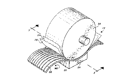
FIG. 1 is a schematic representation of an extended nip press
employing the press blanket of this invention.
FIG. 2 is a cross-sectional view along the cross-machine plane of
a prior art press blanket, illustrating the "barrelling" of the fluid relief
grooves formed therein.
FIG. 3 is a cross-sectional view of the press blanket and engaged
paper web and felt of this invention, taken along section line 3-3 in FIG.
1.
FIG. 4 is a somewhat schematic isometric view of polyurethane
being applied in a ribbon-casting process to form the anisotropic press
blanket of FIG. 3.

CA 02212284 1997-08-0~
DESCRIPTION OF THE PREFERRED EMBODIMENT
Referring more particularly to FIGS. 1-4 wherein like numbers
refer to similar parts, the press blanket 20 of this invention is illustrated
schematically in FIG. 1 in use within an extended nip press 22. The
extended nip press 22 has a backing roll 24 which is opposed to a press
shoe 26. The shoe has a concave surface which conforms to the
cylindrical surface of the backing roll 24 and forms a nip between the
backing roll 24 and the shoe 26. The blanket 20 forms a continuous
loop which extends through the nip between the roll 24 and the shoe
26. A press felt 28 passes over the blanket 20, and a paper web 30 is
supported on the felt as the blanket 20, felt 28, and web 30 pass
, through the nip. The shoe 26 is supported and urged against the roll 24by a hydraulic piston ~not shown). The extended nip press 22 is utilized
in the pressing and drying of the paper web in the pressing and drying
sections of a papermaking machine.
The passage of the blanket 20 over the concave surface of the
press shoe 26 is facilitated by a film of oil which supports and lubricates
the blanket's passage through the nip. The blanket performs several
functions. First, the blanket supports the web and the felt as they pass
through the nip. Second, the blanket prevents the oil film from coming
into contact with or contaminating the paper web. Third, the blanket 20
is provided with a plurality of parallel grooves 32 which extend
circumferentially around the blanket in the machine direction which
provide a route for the escape of water pressed from the belt and the
web.
A prior art blanket 34 is shown in FIG. 2 which utilizes a
conventional polyurethane coating on a backing substrate. The prior art
blanket has a plurality of aligned grooves 36 which are ground into the
resilient urethane layer 38. Urethane ribs 40 are defined between
neighboring grooves 36. When subjected to the pressure of the backing
roll 42 in the extended nip, the ribs 40 are deformed downwardly and

CA 022l2284 l997-08-0~
caused to "barrel" outwardly, thereby partially or completely blocking
the flow of fluid through the grooves. This flow blockage prevents the
blanket 34 from fully relieving the liquid pressed from the paper web as
it passes through the extended nip press and hence causes the extended
nip press to operate at less than optimum efficiency.
As shown in FIG. 3, the improved press blanket 20 of the present
invention has a polyurethane layer 44 which is formed on a looped
substrate 46 which is a woven fabric or scrim. The polyurethane layer
44 has a multitude of narrow diameter fibers 48 which extend generally
in a cross-machine direction. The fibers 48 extend within the raised ribs
of the blanket 20 and provide some restraint to the outward bowing of
the ribs. By preventing barreling, the reinforcing fibers help to keep the
grooves 32 unobstructed and ready to channel water away from the nip.
The fibers 48, however, extend predominantly in the cross-machine
direction, so that they do not significantly restrict the flexibility of the
blanket 20 in the machine direction, and hence do not hinder the ability
of the blanket to conform to the press shoe 26 and the backing roll 24.
The formation of the press blanket 20 is illustrated in FIG. 4. The
blanket 20 is formed by first looping the bare fabric substrate 46 around
~F two support rollers 52. A top run 54 is defined between the two
support rollers, and it is in this region that polyurethane is applied to the
substrate 46. One of the rollers 52 is driven by an electric motor to
advance the substrate along the run 54 as desired.
The two component polyurethane is supplied from two supply
tanks, the A Tank, and the B Tank, as shown in FIG. 4. The two
components are supplied under pressure through two flexible hoses 60
to a mixing head 62 which is closely spaced from the substrate surface.
The mixing head can be driven back and forth across the looped blanket
by any appropriately designed mechanical device. In an exemplary
embodiment, the head 62 is mounted in a ball and screw relation to a

CA 02212284 1997-08-0~
screw rod 64 which extends across the substrate 46 in the cross
machine direction of the blanket 20. An electric motor 66 drives the
head 62 in a back and forth motion, which, together with the machine-
direction motion of the substrate on the support rollers 52, enables
polyurethane to be laid down on the substrate over the entire surface of
the looped blanket 20. An example of a head which may be used is the
FFH head from Edge-Sweets Company, Grand Rapids, Michigan.~
Fibers are introduced directly into the mixing head by a third
stream dispensing device which can also vary the amount of fibers that
10 are mixed into the polyurethane. The fibers are aligned during the flow
of material out of the mixing head such that they are deposited in the
direction of the movement of the mixing head.
The urethane-fiber mix is thus applied as a continuous ribbon.
The width and thickness of the ribbon will depend on how fast the
~5 material is flowing. The ribbon may be from 1/4 inch to 2 inches wide.
The thickness of the applied mixture may be from 30/1000 inches to
150/1000 inches. The length of the fibers is from 1/1 6th to 2 inches.
It is desirable that a high aspect ration between the length and the
diameter of the fibers be maintained. Various types of fibers may be
employed, for example glass, graphite, KEVLAR (a trademark of Du Pont
Co. for an aramid fiberJ, UHMW polyethylene, carbon fiber, or other
. .
reinforcing material.
Once the urethane fiber mix has been applied, the blanket 20 may
be ground to a consistent thickness, and the grooves 32 milled into the
urethane layer. As shown in FIG. 3, the fibers 48 provide anisotropic
reinforcement to the urethane, and hence resist barrelling of the
grooves, while at the same time retaining the flexibility of the blanket in
the machine direction.
It is understood that the invention is not limited to the particular
construction and arrangement of parts herein illustrated and described,

CA 02212284 1997-08-05
,
but embraces such modified forms thereof as come within the scope of
the following claims.
~ . ~

Representative Drawing
A single figure which represents the drawing illustrating the invention.
Administrative Status

2024-08-01:As part of the Next Generation Patents (NGP) transition, the Canadian Patents Database (CPD) now contains a more detailed Event History, which replicates the Event Log of our new back-office solution.

Please note that "Inactive:" events refers to events no longer in use in our new back-office solution.

For a clearer understanding of the status of the application/patent presented on this page, the site Disclaimer , as well as the definitions for Patent , Event History , Maintenance Fee  and Payment History  should be consulted.

Event History

Description Date
Inactive: IPC assigned 2022-08-11
Application Not Reinstated by Deadline 2000-08-07
Time Limit for Reversal Expired 2000-08-07
Inactive: Abandoned - No reply to s.30(2) Rules requisition 1999-09-13
Deemed Abandoned - Failure to Respond to Maintenance Fee Notice 1999-08-05
Inactive: S.30(2) Rules - Examiner requisition 1999-03-11
Inactive: IPC assigned 1998-04-03
Inactive: IPC assigned 1998-04-01
Inactive: IPC assigned 1998-03-31
Inactive: First IPC assigned 1998-03-31
Inactive: IPC removed 1998-03-31
Inactive: Single transfer 1998-03-20
Application Published (Open to Public Inspection) 1998-02-13
Inactive: First IPC assigned 1997-10-27
Inactive: IPC assigned 1997-10-27
Classification Modified 1997-10-27
Inactive: Courtesy letter - Evidence 1997-10-21
Filing Requirements Determined Compliant 1997-10-14
Inactive: Filing certificate - RFE (English) 1997-10-14
Application Received - Regular National 1997-10-10
Request for Examination Requirements Determined Compliant 1997-08-05
All Requirements for Examination Determined Compliant 1997-08-05

Abandonment History

Abandonment Date Reason Reinstatement Date
1999-08-05

Fee History

Fee Type Anniversary Year Due Date Paid Date
Registration of a document 1997-08-05
Application fee - standard 1997-08-05
Request for examination - standard 1997-08-05
Owners on Record

Note: Records showing the ownership history in alphabetical order.

Current Owners on Record
BELOIT TECHNOLOGIES, INC.
Past Owners on Record
EUGENE L. SLAGOWSKI
PAUL MCCARTEN
Past Owners that do not appear in the "Owners on Record" listing will appear in other documentation within the application.
Documents

To view selected files, please enter reCAPTCHA code :


To view images, click a link in the Document Description column. To download the documents, select one or more checkboxes in the first column and then click the "Download Selected in PDF format (Zip Archive)" or the "Download Selected as Single PDF" button.

List of published and non-published patent-specific documents on the CPD .

If you have any difficulty accessing content, you can call the Client Service Centre at 1-866-997-1936 or send them an e-mail at CIPO Client Service Centre.


Document
Description 
Date
(yyyy-mm-dd) 
Number of pages   Size of Image (KB) 
Description 1997-08-05 7 255
Claims 1997-08-05 3 69
Abstract 1997-08-05 1 26
Cover Page 1998-03-03 2 73
Drawings 1997-08-05 3 158
Representative drawing 1998-03-03 1 15
Filing Certificate (English) 1997-10-14 1 164
Courtesy - Certificate of registration (related document(s)) 1998-06-22 1 116
Reminder of maintenance fee due 1999-04-07 1 111
Courtesy - Abandonment Letter (Maintenance Fee) 1999-09-02 1 187
Courtesy - Abandonment Letter (R30(2)) 1999-11-08 1 172
Correspondence 1997-10-17 1 31