Note: Descriptions are shown in the official language in which they were submitted.
CA 02212286 1997-08-OS
WO 96/24308 PCT/US96/01550
- 1 -
EXPANDABLE TRANSLUMINAL GRAFT PROSTHESIS FOR
REPAIR OF ANEURYSM AND METHOD FOR IMPLANTING
Description
Technical Field
The invention relates to transluminal graft prostheses for
the repair of aneurysms and a method for implanting them.
Backaround of the Ir~vention
The abdominal aorta is prone to aneurysmal dilation
between the renal and iliac arteries. The attenuated wall of the
aneurysm is unable to withstand arterial pressures so that
dilation tends to progress to a point where rupture is likely.
The highly invasive procedure necessary for conventional repair
of an aortic aneurysm consists of an abdominal incision,
dissection of the arteries, and the interruption of blood flow to
the lower body and legs while an artificial graft is implanted to
bypass the aneurysm. Such invasive surgical repair of vital
lumens has profound undesirable effects on the respiratory and
cardiovascular systems of elderly patients who typically require
the operation. The operation is expensive and entails significant
life threatening risk. It is therefore highly desirable to.
replace conventional surgical repair with a less traumatic, less
complicated and safer procedure. The present invention serves
these needs, and is particularly well adapted to reconstruction
of an abdominal aortic aneurysm. The prosthetic graft of this
invention will provide a resilient conduit, bridging the aneurysm
and reducing the risk of rupture, without the attendant morbidity
and expense of conventional surgical repair. The invention,
however, is not limited to aortic aneurysm repair and has
applications in a variety of situations in which corporeal lumen
repair is required.
There are several devices already existing which are
3 0 stated to be useful for the remote repair of corporeal lumens .
U.S. Patent No. 4,512,338, issued to Balko et al., discloses a
CA 02212286 1997-08-OS
WO 96/24308 PCT/US96/01550
- 2 -
device for-transluminal repair of, and restoring potency of, a
weakened or damaged corporeal vessel. The device consists of a
nitinol wire, previously memory-shaped into a longitudinal coil, '
which is cooled and reformed into a straight wire and inserted
into the vessel requiring repair. When placed in the body and '
stripped of heat insulating means, the wire warms and returns to
its preselected coiled dimensions to support the vessel wall. Use
of a device such as nitinol wire may be undesirable because there
is a danger of~possibly puncturing or lacerating the lumen wall
during the emplacement process. Another problem lies in fitting
the prostheses to the vessel because the prosthesis does not
assume its final shape (and length) until itis inside the artery.
The exact position of both ends of- the prostheses is very
important due to the proximity of vital arteries to the ends of
the aneurysm. Yet another problem with -these devices is the
difficult task of attaching the sleeve to the wire support because
the wire is many times longer than the sleeve at the time it is
inserted.
U.S. Patent No. 4,140,126, issued to Choudhury, discloses
a device for repairing an aneurysm. The device is mounted on the
outside of a carrier catheter, and is positioned in the vessel in
a collapsed form, smaller in diameter than that of the vessel.
The device _is then expanded onto the vessel wall by means of a
mechanical expanding apparatus which is controlled by the user
from outside the body by means of a wire. Upon expansion,
anchoring pins are driven into the vessel wall. The wire is
positioned on the outside of the carrier catheter, and is held in
place by passing through many slip rings, each of which is firmly
attached to the catheter. The slip rings permit the wire to slide
when remotely operated. The wire is also attached to the
expanding means at its proximal (downstream) end by slip couplings '
which permit the wire and expansion means to.pass through the
couplings during the expansion process. This device is ,
mechanically complex and may not apply sufficient force to drive
the pins into an atherosclerotic aorta or seal the graft to the
arterial lumen. Furthermore, there is nothing to shield the
CA 02212286 1997-08-OS
WO 96/24308 PCT/US96/01550
- 3
vessel wall from the sharp pins while the device is moving from -
the insertion point to the point of repair. The pins are
interspaced in folds of the graft material and could protrude from
these folds while the device is moved into position. This could
result in damage to the vessel wall in locations remote from the
repair.
U.S. Patent No. 4,787,899, issued to Lazarus, describes
a system of positioning a graft within a body lumen. The graft
is loaded into a guide which is inserted into the lumen. An
inflatable balloon is used to anchor the distal (upstream) end of
the graft onto the wall of the lumen, and then the guide is pushed
upstream, pulling the folded graft out of the guide and onto the
wall of the lumen, where staples at the proximal (downstream) end
anchor into the wall of the lumen. Because the graft is folded
or crimped axially, there is no sure method ofdetermining where
the -expanded graft will position itself on the wall of the lumen,
other than by measuring from the point of initial contact on the
wall. This is difficult to do utilizing the remote insertion
procedure. Also, the balloon providing the anchor for the distal
(upstream) end of the graft while the guide is moved upstream may
not provide enough pressure on the wall of the vessel to prevent
slippage which could result in misplacement of the graft. The
axial crimping used in these grafts may not impart radial
elasticity and standard graft materials may not have sufficient
-elasticity as an intrinsic property. The small amount of apparent
elasticity present in knitted grafts is actually a form of
deformability in that expansion in one direction is accompanied
by contraction in another. This means that the "guide" should be
very close in size to the lumen of the vessel. As such, it should
be introduced directly into the vessel to be repaired, rather than
via a distant (much smaller) vessel. Also, the large guide may
be difficult to withdraw through the graft after placement since --
it presents an open edge which might catch on any irregularities
of the lumen:
The report, Percutaneously Placed Endovascular Grafts for
Aortic Aneurysms: Feasibility Study, from the Department of
CA 02212286 1997-08-OS
WO 96/24308 PCT/iTS96/01550
- 4 -
Diagnostic Radiology, University of Texas M.D. Anderson Cancer
Center, printed in 170 Radiology 1033-37 (1989), deals with a
self-expanding graft consisting of several stems connected in a '
chain. Two stainless steel struts run down the length of the
chain, forming a rigid structure along the longitudinal axis. The '
structure is partially covered in a secured nylon sheath, is
compressed radially, and is introduced into a lumen via a catheter
and a blunt-tipped introduces wire used to push the graft up the
catheter and into position. Placement is secured by withdrawing
the catheter while holding the introduces wire stationary. This
device may be difficult to insert because a chain structure is
difficult to push unless it is rigid. The-rigidity would make it
very difficult to negotiate femoral and iliac arteries which are
frequently tortuous. Precise positioning of the graft could be
impaired because the pusher wire is not attached to the graft.
This poses the potential for mispositioning of the graft during
the withdrawal of the sheath. Hemorrhage could also be a major
problem with this method of introduction. The introduces sheath
is carried into position on the outside of a dilator, which must
be removed before the graft can be inserted, leaving the sheath
as a conduit from the artery to the outside of the body. The need
to introduce the graft complicates the use of hemostatic seals on
the sheath. Only one of these grafts carried barbs. The other
model showed a tendency to migrate. There is a possibility that
the sheathed wall of the barbed device could be breached by the
barbs during transfer of the graft to the point of repair because
the graft is pushed though the entire length of the catheter with
the springs expanded against the inner wall of the catheter.
Also, the wide mesh of the materialused may not form a barrier
to blood leaks, so that tine aneurysm could be exposed to arterial
pressure.
Endovascular repair of abdominal aortic aneurysm avoids
much of the morbidity and mortality associated with conventional
surgery. Most patients with abdominal aortic aneurysm lack a
segment of non-dilated aorta suitable for attachment of the down
stream (caudal) end of a straight (single-lumen) endovascular
CA 02212286 1997-08-OS
WO 96/24308 PCT/US96/01550
- 5 -
graft. In these patients a more secure outflow is provided by
attaching the two caudal ends of a bifurcated graft to the iliac
arteries.
The caudal ends of bifurcated grafts cannot extend to the
sites of arterial access in the groin without impairing internal
iliac arterial flow, which is an important source of spinal and
colonic perfusion after aortic aneurysm repair. Therefore, direct
control of the caudal ends of bifurcated grafts is not possible,
resulting in a tendency to kinking, twisting and displacement, all
of which have complicated previous attempts to apply this
approach. The devices and techniques described below provide a
means of accurate, hemostatic and permanent insertion of a
bifurcated graft, with provision for the prevention of correction
of these potential complications.
Although ideally suited for its intended purpose, one
problem noted during surgical placement of the prosthesis assembly
of the present invention involved undesirable tension being
exerted on the prosthesis assembly and, in particular, on the main
spring assembly during release of the ipsilateral spring assembly.
In particular, when the mooring loops attached to the main
retainer assembly of the delivery system and the main spring
assembly of the prosthesis assembly have been released, all the
retention force is placed on the main spring assembly of the
prosthesis while the central elongated member of the delivery
system is being withdrawn to release the ipsilateral spring
assembly. This undesirable retention force can dislodge the main
spring assembly of the prosthesis or cause trauma to the wall of
the aorta due to the barbs extending from the main spring
assembly.
Summary of the Invention
The foregoing retention problem is solved and a technical
advance is achieved in an improvement to the transluminal
arrangement of the present invention. The improvement includes
substituting for the stent boot of the transluminal arrangement
a sheath having a longitudinal bore that closely approximates the
CA 02212286 1997-08-OS
WO 96/24308 PCT/US96/01550
- 6 -
cross-sectional shape of the elongated member of the delivery
system and is slidably and longitudinally positioned around the
elongated member of the delivery assembly. The bore of the sheath '
closely approximates the cross-sectional shape of the elongated
member to advantageously minimize blood flow therethrough. The '
bore at and in the vicinity of the cranial end of the sheath is
enlarged to receive one end of the prosthesis assembly.
A further improvement in the transluminal arrangement is
the inclusion of a slit extending longitudinally from one end of
the sheath, which is adapted to slide the sheath along the
elongated member and release the one end of the prosthesis
assembly. Movement of the sheath with respect to the elongated
member of the delivery assembly advantageously maintains the
prosthesis assembly in a fixed relative position without undue
tension being placed on the prosthesis assembly.
Another- improvement inthe transluminal arrangement
includes an annular groove about the caudal end of the sheath in
which a fastener is positioned therein to maintain the
longitudinal slit in a closed position. The fastener such as a
suture material tie is cut to allow the slit of the sheath to be
opened.- The elongated member of the delivery system is positioned
through this slit so as to slide the sheath caudally along the
elongated member and release the one end of the prosthesis
assembly without any undue tension being placed on the prosthesis
assembly.
For purposes of radiographic visualization, the sheath
includes a radiopaque material such as a polyether block amide
elastomer.
Still another improvement in the transluminal arrangement
includes visual markers positioned longitudinally on the elongated
member of the delivery system. These-markers are also positioned
distally and proximally of the prosthesis assembly to indicate
advantageously the orientation of the prosthesis assembly in the
transluminal arrangement during the -prosthesis placement
procedure.
CA 02212286 1997-08-OS
WO 96/24308 PCT/US96/01550
The present invention provides a transluminal graft
prosthesis that can be safely and precisely positioned.
An object of the present invention is to provide a
prosthesis for the safe repair of aneurysms without the risks
associated with invasive surgical repair.
It is another object of the invention to provide a
coupling between a plurality of spring expanding assemblies that
provides a relatively flexible prosthesis during insertion, a
relatively rigid prosthesis after attachment, and also maintains
the alignment of the springs when the prosthesis is compressed by
an extrusion device applied to one end.
The present invention provides a device for transluminal
grafting of a prosthesis in a lumen, comprising: a tubular
introduces sheath having a longitudinal bore; a prosthesis
comprising a tubular graft having a longitudinal bore and disposed
in the longitudinal bore of the tubular introduces sheath, the
graft being expandable radially to substantially conform to the
interior wall of a lumen; a spring expanding assembly permanently
attached to the tubular graft to expand the graft so that it
substantially conforms to the interior wall of a lumen when the
graft is removed from the introduces sheath; an anchoring means
for permanently attaching the graft to an interior wall of a
lumen; a tubular carrier means having a longitudinal bore and
disposed in the longitudinal bore of the tubular graft, the
tubular carrier means provided with a plurality of apertures; a
central control means for maintaining the axial position of the
prosthesis during removal of the introduces sheath, the central
control means disposed in the longitudinal bore of the tubular
carrier means; and mooring loops engaging the prosthesis and
passing through the apertures in the tubular carrier means to
engage the central control means.
The present invention also provides a method for
engrafting a prosthesis in a lumen comprising the steps of
a) providing an access to the lumen; b) providing a device for '
engrafting the prosthesis comprising: a tubular introduces sheath
having a longitudinal bore; a tubular graft having a longitudinal
CA 02212286 1997-08-OS
WO 96/24308 PCT/US96/01550
_ g _
bore and disposed in the longitudinal bore- of the tubular
introducer sheath, the graft being expandable radially to
substantially conform to the interior wall of a lumen; a spring '
expanding assembly permanently attached to the tubular graft to
expand the graft so that the graft substantially conforms to the '
interior wall of a lumen when the graft is removed from the
introducer sheath; an anchoring means for permanently attaching
the graft to an interior wall of a lumen; a tubular carrier means
having a longitudinal bore and disposed in the longitudinal bore
of the tubular graft, the tubular carrier means provided with a
plurality of apertures; a central control means for maintaining
the axial position of the prosthesis during removal of the
introducer sheath, the central control means disposed in the
longitudinal bore of the tubular carrier means; mooring loops
engaging the prosthesis and passing through the apertures in the
tubular carrier means to engage the central control means;
c) inserting the device and urging the device into a lumen to a
desired location within the lumen; d) withdrawing the tubular
introducer sheath to expose the graft; e) disengaging the central
control means from the mooring loops; and f) removing the tubular
introducer sheath, carrier means, and central control means.
The present invention provides an occlusive umbrella
comprising: a spring expanding assembly having a proximal and a
distal end; barbs attached to the proximal end of the spring
means; a tubular graft having a longitudinal bore and having a
proximal end and a distal end, the tubular graft open at the
proximal end and closed at the distal end, the graft attached to
the spring; a dilator having a distal end and a proximal end, the
proximal end of the dilator attached to the distal end of the
tubular graft; a-first tubular catheter having a proximal end, a
distal end, and a longitudinal bore, the first tubular catheter .
inserted into the longitudinal bore of the graft and attached to
the proximal- end of the dilator; a second tubular catheter having
a proximal end, a distal end, and a longitudinal bore, the distal
end of the second catheter communicating with the proximal end of
the first catheter; a flexible rod having a proximal end and a
CA 02212286 1997-08-OS
WO 96/24308 PCT/LTS96/01550
g _
distal end, the distal end of the flexible rod inserted into the
longitudinal opening of the first catheter and the longitudinal
opening of the second catheter, the distal end of the flexible rod
contacting the dilator head.
The present invention provides a flexible spring alignment
and compression resistance assembly comprising: a first and
second spring expanding assembly each having a plurality of
apertures; a plurality of retaining shafts each having.a first end
and a second end, the shafts having a diameter equal to or smaller
than the apertures of the first and second spring expanding
assemblies, the first end of each of the retaining shafts slidably
inserted into one of the apertures of the first spring expanding
assembly and the second end of each of the retaining shafts
slidably inserted into one of the apertures of the second spring
expanding assembly, a first protrusion attached to each of said
first ends and a second protrusion attached to each of said second
ends, the protrusions larger than the apertures of the first and
the second spring expanding assemblies to prevent the protrusions
from passing through theapertures.
The present invention also provides a flexible spring
alignment and compression resistance assembly comprising: a first
spring expanding assembly having a plurality of apertures; a
second spring expanding assembly; a plurality of retaining shafts
each having a first end and a second end, the shafts having a
diameter equal to or smaller than the apertures of the first
spring expanding assembly, the first end of each of the retaining
shafts slidably inserted into one of the apertures of the first
spring expanding assembly and the second end of each of the
retaining shafts attached to the second spring expanding assembly,
a protrusion attached to each of said first-ends,. the protrusions
larger than the apertures in the first spring expanding assembly
to prevent the protrusions from passing through the apertures.
The foregoing problems are solved and a technical advance
is achieved in an illustrative prosthesis for repairing an
aneurysm. The prosthesis comprises a bifurcated endovascular
graft having a main body and first and second limbs extending
CA 02212286 1997-08-OS
WO 96/24308 PCT/US96/01550
- 10 -
therefrom. The main body includes a main bore extending
longitudinally therein and having a cranial orifice. The first
limb includes a first bore extending longitudinally therein,
communicating with the main bore, and having a first caudal
orifice. The second limb includes a second bore extending
longitudinally therein, communicating with the main bore and
having a second caudal orifice. The prosthesis also comprises a
first imageable marker extending longitudinally along the first
limb and a second imageable marker extending longitudinally along
the first limb and spaced at least a predetermined distance away
from the first marker.
The invention also comprises an illustrative prosthesis
delivery system for percutaneously inserting the prosthesis in an
aneurysm. The delivery system comprises a tubular introducer
sheath having a sheath bore extending longitudinally therein and
a central carrier coaxially positionable within the sheath bore
of the sheath. The central carrier includes a head region having
a dimension approximating said sheathbore, a shaft region having
a dimension approximating_the sheath bore, and a stem region
positioned between the head and shaft regions and having a
dimension smaller than the sheath bore for positioning the
prosthesis therearound and in the sheath bore.
The present invention also includes an illustrative method
of inserting a bifurcated prosthesis in an aneurysm utilizing the
prosthesis delivery system. The method comprises the steps of
percutaneously obtaining cross access with a first guide between
femoral arteries positioned caudal to the aneurysm; percutaneously
obtaining access to a lumen of the aneurysm with the second guide;
and positioning the prosthesis in the aneurysm and one limb
thereof in one ofthe femoral arteries- with the prosthesis
delivery system and the second guide. The method also comprises
the steps of positioning another limb of the prosthesis in the
other of the femoral arteries with the first guide and releasing .
the prosthesis from the delivery system when the prosthesis is
positioned in the aneurysm.
CA 02212286 1997-08-OS
WO 96/24308 PCT/US96/01550
- 11 -
The invention is described in greater detail below based
on a few selected embodiments. Those skilled in the art will
appreciate that the prosthesis according to the invention can be
applied in various modifications.
The foregoing problems are also solved and another
technical advance is achieved by an illustrative transluminal
arrangement for positioning a prosthesis assembly in a particular
bifurcated lumen. The bifurcated lumen includes, for example, the
main lumen ofthe aorta and the branch lumens of the common iliac
arteries. An aneurysm is commonly found in the aorta just
proximal the branching of the common iliac arteries. A prosthesis
assembly for positioning in the aneurysm of the bifurcated lumen
includes a bifurcated endovascular graft having a main body and
first and second limbs extending therefrom. The assembly also
includes main and branch limb spring assemblies each having a
compressed state. The main bore spring assembly radially expands
to substantially conform the main body of the graft to the
interior wall of the aortal lumen. The ipsilateral and
contralateral limb spring assemblies radially expand to conform
the limbs of the graft to the interior walls of the branch lumens
o-f the ipsilateral and contralateral iliac arteries. The
transluminal arrangement comprises containers such as sheaths for-
containing each of the spring assemblies in a compressed state and
a retainer assembly positioned in the main and ipsilateral bores
of the graft for retaining the prosthesis assembly at the aneurysm
in the bifurcated lumen while the main outer sleeve is withdrawn
from the prosthesis assembly, thereby releasing the main spring
assembly from its compressed state. Branch limb retainer means
attached to the ipsilateral and contralateral spring assemblies
retain these spring assemblies in respective container sheaths.
The main container includes an outer sheath with a
longitudinal bore wherein the prosthesis assembly is positioned.
The ipsilateral and contralateral containers each include a sheath
with a longitudinal bore wherein the ipsilateral and contralateral
spring assemblies are positioned and contained in their compressed
state.
CA 02212286 1997-08-OS
WO 96/24308 PCT/~1596/01550
- 12 -
The main retainer assembly of the transluminal arrangement
comprises an elongated member having a dilator head at the distal
end thereof, a main attachment assembly for temporarily attaching
the main spring assembly to the elongated member and a branch limb
attachment assembly for temporarily attaching the branch limb '
spring assembly to the elongated member. An inner catheter is
positioned through the elongated member for releasing at least one
of the main and ipsilateral attachment assemblies either during
or after removal of the main and first sheaths. A control limb
delivery catheter forms a second release assembly, which is
temporarily attached to the contralateral spring assembly with an
attachment suture extending therethrough for releasing the
contralateral spring assembly when positioned in the contralateral
common iliac artery.
The main and ipsilateral attachment assemblies each
comprise attachment sutures for temporarily pulling the main and
ipsilateral spring assemblies inwardly to their compressed state
when the prosthesis assembly is positioned within the main sheath.
The transluminal arrangement also includes a method of
positioning the prosthesis assembly at the aneurysm in the
bifurcated lumen.- The method includes providing cross access to
the branch lumens and inserting a cross femoral wire guide between
the branch access sites. The transluminal arrangement is
positioned in the bifurcated lumen via the ipsilateral access
site. The outer sheath is withdrawn from the prosthesis assembly
and the contralateral limb is positioned with the aid of the cross
femoral guide pulling the control limb delivery catheter of the
transluminal arrangement. The attachment sutures are released
from the prosthesis assembly when positioned at the aneurysm in
the bifurcated lumen allowing the main spring assembly to radially
expand and conform the graft to the aorta. The branch limb .
containers of the transluminal arrangement are also withdrawn from
the branch spring assemblies which then radially expand the ,
ipsilateral and contralateral limbs of the graft to the common
iliac arteries so as to advantageously prevent retrograde flow of
blood back to the aneurysm. Similarly, the main spring assembly
CA 02212286 1997-08-OS
WO 96/24308 PCT/US96/01550
- 13 -
conforms the cranial orifice of the main body of the graft to the
wall of the aorta preventing antegrade flow of blood into the
aneurysm.
Brief Description of the Draw~.ncrs
FIG. 1 is a side view of a tubular graft of the instant
invention;
FIG. 2 is a side view of a spring expanding assembly of
the instant invention;
FIG. 3 is a top cross-sectional view of a spring expanding
assembly shown in FIG. 2 taken along A-A;
FIG. 4 is a top cross-sectional view of a spring expanding
assembly shown in FIG. 2 taken along B-B;
FIG. 5 is a side view of alternative elbows of the spring
expanding assembly of the instant invention;
FIG. 6 shows a spring expanding assembly (with a barb
attached) sutured to the graft;
FIG. 7 is a side view of a flexible spring alignment and
compression resistance assembly;
FIG. 8 shows the elbow and retaining bar of the flexible
spring alignment and compression resistance assembly of FIG. 7;
FIG. 9-A is a longitudinal cross-sectional view of two
compressed spring expanding assemblies connected by the flexible
spring alignment and compression resistance assembly of FIG. 7;
FIG. 9-B is a longitudinal cross-sectional view of two
uncompressed spring expanding assemblies connected by the flexible
spring alignment and compression resistance assembly of FIG. 7.
FIG. 10 is a side-view of a flexible spring alignment and
compression resistance assembly and shows the retaining bar
rigidly attached to one of the spring expanding assemblies;
FIG. 11 a.s a longitudinal cross-sectional view of a
tubular carrier of the instant invention shown with a dilator head -
at the distal (upstream) end;
FIG. 12 is a longitudinal cross-sectional view of a
"muzzle loading" apparatus of the instant invention;
CA 02212286 1997-08-OS
WO 96124308 PCT/US96101550
_ 14
FIG. 13 is a longitudinal cross-sectional view of the
proximal (downstream) end of the introducer sheath;
FIG. 14 is a longitudinal cross-sectional view of the
aorta and iliac arteries and shows a dilator head, introducer
sheath, tubularcarrier, arteriotomy, and central control means;
FIG. 15 is a longitudinal cross-sectional view of the
aorta and iliac arteries and shows a graft implanted in the aorta
on either side of an aneurysm;
FIGS. 16 and 17 are longitudinal cross-sectional views of
an apertured tubular carrier showing mooring loops and central
control means;
FIG. 18 is a longitudinal cross-sectional view of an
alternative means of graft attachment;
FIG. 19 is a longitudinal cross-sectional view of an
occlusive umbrella; and
FIG. 20 is a longitudinal cross-sectional view of the
aorta and the iliac arteries showing- the use of a graft in
conjunction with an occlusive umbrella and a femoro-femoral graft
FIG. 21.depicts a segment of a self-expanding stent;
FIG. 22 depicts a bifurcated graft;
FIG. 23 depicts a carrier of the present invention;
FIGs. 24 and 25 depict alternative embodiments of a sheath
with a tapered cranial external surface;
F'IGs. 26 and 27 depict a carrier of the present invention;
FIG. 28 depicts tubular extensions sutured to a graft of
the present invention;
FIG. 29 depicts an alternative mechanism for attaching the
tubular extensions to a graft of the present invention;
FIG. 30 depicts a single loop of suture material for-
applying traction to a caudal limb of the present invention;
FIG. 31depicts attachment to multiple points on a caudal .
limb of the pre-sent invention;
FIGS. 32 and 33 depict catheter side ports for allowing ,
traction to be applied at multiple points;
FIG. 34 depicts tension transmitted through a short
suture;
CA 02212286 1997-08-OS
WO 96/24308 PCT/US96/01550
- 15 -
FIGs. 35 and 36 depict a caudal limb control catheter of
the caudal limb control system of the present invention;
FIG. 37 depicts a suture encircling a catheter of the
contralateral lumen access guidance system;
FIG. 38 depicts access to the ipsilateral limb lumen by
an insertion delivery wire;
FIG. 39 depicts a distal stent insertion device of the
present invention;
FIG. 40 depicts a contralateral limb straightening device;
FIG. 41 depicts an alternative limb straightening device;
FIG. 42 depicts a sectioned view of a twist-preventing,
double lumen catheter;
FIG. 43 depicts a partially sectioned view of a
transluminal arrangement of the present invention for positioning
a prosthesis assembly at a particular position in a bifurcated
lumen;
FIG. 44 depicts a partially sectioned side view of
ipsilateral limb spring assembly of the prosthesis assembly and
stmt boot of the transluminal arrangement of FIG. 43;
FIG. 45 depicts a partially sectioned side view of
contralateral spring assembly of the--prosthesis assembly and
control limb delivery catheter of FIG. 43;
FIG. 46 depicts a partially sectioned side view of
contralateral stmt boot temporarily attached to control limb
delivery catheter of FIG. 45;
FIG. 47 depicts a prosthesis assembly of the present
invention positioned in the bifurcated lumen of the aorta and
common iliac-arteries extending therefrom;
FIGs . 48 and 49 depict the method of deploying a cross
femoral wire guide between femoral access sites positioned on
opposite sides of the groin;
FIG. 50 depicts a partially sectioned view of an
improvement in the transluminal arrangement of FIG. 43;
FIG. 51 depicts a partially sectioned view of ipsilateral
limb spring assembly of the prosthesis assembly and the tubular
sheath of the transluminal arrangement of FIG. 50; and
CA 02212286 1997-08-05
WO 96/24308 PCT/LTS96/01550
- 16 -
FIG. 52 depicts the tubular sheath of FIG. 50 with the
elongated member of the arrangement positioned through a slit at
the caudal end of the tubular sheath.
Derailed Descrip ion
The graft 1 shown in FIG. 1 is in the form of an elongated
cylindrical tube defining a longitudinal bore that is multiply
crimped 3, or folded over to facilitate the compression and
expansion of the graft as the diameter 5 of the graft decreases
and increases. Transverse elasticity may also be achieved or
enhanced through inherent properties of either the weave or
constituent fibers used to construct the graft 1. The graft 1 is
preferably constructed from a material such as woven multifilament
polyester (such as DacronT"') , which is known to be sufficiently
biologically inert, non-biodegradable, and durable to permit safe
insertion inside the human body. Any material with such qualities
may be used, however_ Polyester is also known to excite fibrous
ingrowth which will secure the graft 1 to the wall of the lumen
within a few months of its_insertion.
The typical graft 1 is of fixed length and relatively
inelastic along its longitudinal axis. A variable length graft
may also be used and could be constructed by either having two
pieces of graft, one inserted within the other in a telescopic
arrangement, capable of being manipulated within the body, or
having one continuous piece of material that is folded back on
itself. A spring within this area of the graft ensures apposition
of the various layers at this level ; the outer layers having a
slightly smaller maximum diameter to provide a buttress against
which the spring can expand in the absence of a secure arterial
wall. Variability of length may also be achieved by providing
elasticity along the longitudinal axis of the graft as a property
of graft material or by having one or more elastic sections of
such material within the main body of the graft.
The spring assembly 6 of FIG. 2 includes arms 15 which are
bent taform elbows 7. Surgical barbs 10 having sharp tips 13 are
attached to the arms 15 and protrude from the elbows 7. FIG. 3
CA 02212286 1997-08-OS
WO 96/24308 PCT/US96/01550
- 17 -
is a top cross-sectional view of the spring assembly 6 of FIG. 2
taken along A-A showing six elbows 7 and associated barbs 10.
FIG. 4 is a top cross-sectional view of the spring assembly 6
taken along B-B showing twelve arms 15 which extend from the six
elbows 7 shownin FIGS. 2 and 3. A spring assembly 6 is typically
formed from a continuous piece of fine gauge stainless steel
spring wire that, if opened out, would appear in the shape of a
zig-zag with multiple elbows 7. FIG. 5 shows that these elbows
7 may be simple arches 7, recurved arches 42, or apertured 60.
The advantage of simple arches 7 is that the spring assembly 6
expands the longitudinal aperture of the graft 1 more evenly. The
advantage of the recurved arches 42 is that they collapse more
readily and are more durable. The apertured elbows 60 are used
in the flexible spring alignment and compression resistance
assembly. The two ends of the piece of bent wire are permanently
attached end-to-end so as to form a circular structure, e.g.,
FIGS. 2, 3 and 4. FIG. 6 shows a portion of the spring assembly
6 with a barb 10 attached to an arm 15 of the spring assembly 6.
The spring assembly 6 is_sutured to the graft 1 with a non-
biodegradable thread 36. The spring assembly 6 may also be
constructed out of other inert metals such as titanium, or a
plastic. When expanded, the spring assembly 6 is circular in
shape when viewed from above, and may have a diameter, when in a
relaxed state, equal to approximately twice the diameter of a
lumen into which the graft 1 is to be inserted. The spring
assembly 6 is typically attached to the inside of the cylindrical
graft 1 at the distal (upstream) end or both ends of the graft 1
by sutures 36 of non-biodegradable material. The sutures 36 attach
to the spring assembly 6 in such a way that the majority of the
spring assembly 6 is covered by the graft material 1. Other
embodiments may incorporate spring assemblies 6 being attached to
the outside of the tubular graft 1 which would present a smoother
surface to the flowing blood but has the-drawback that the graft
1 would be in less intimate contact with the wall of the lumen.
-- The spring assembly 6 on the distal (upstream] end of the
graft 1 has small surgical barbs 10 firmly attached to the spring
CA 02212286 1997-08-OS
WO 96/24308 PCT/US96/01550
- 18 -
assembly 6. The spring assembly 6 at the proximal (downstream)
end of the graft may also be provided with barbs. The attachment
of the barbs 10 to the graft 1 or spring assembly 6 must be
permanent and can be either welded, brazed, or coupled in a
fashion that is both biologically acceptable, and yet strong
enough to withstand long-term stress. These barbs 10 spread
radially outward from the longitudinal axis of the graft 1, such
that when the spring assembly 6 opens inside the lumen, the barb
tips 13 will come into contact with and engage the wall of the
blood vessel to be repaired. The barb tips 13 will become
imbedded in the wall through both the driving action of the spring
assembly 6 and the pressure created by the flow of blood through
the graft 1. The barb tips 13 are sharp and may be curved
slightly downward toward the graft 1 to provide a more secure
anchor in the -direction of blood flow. The barbs 10 are
positioned so that they are further upstream than the elbows 7 of
the distal (upstream) spring assembly 12, and are of such a size
that the wall of the blood vessel is not punctured or pierced when
the barb tips 13 are firmly_embedded therein. Attaching the barbs
10 to the spring assembly 6 via shafts bonded to the spring
assembly 6 at the middle of one of the two arms 15 extending from
an elbow 7 of the spring assembly 6 permits the barb tip 13 to
slightly retract or rotate when compressed for loading into the
introducer sheath 4 (as best seen in FIG. 6).
Though the spring assembly 6 is typically sutured only to
the ends of the graft 1, several such spring assemblies 6 may also
be connected to owe another for added strength. This is necessary
in embodiments of the prosthesis that require the graft to resist
compression during removal from, the introducer 4. Some
flexibility is retained by connecting the spring assemblies 6 to
each other -in a way that permits separation (but not overlapping
or misalignment) of adjacent spring elbows 60. Fig. 7 illustrates
such a flexible spring alignment and compression resistance ,
assembly 49 and shows a first spring arm 50 and a second spring
arm 52 connected via a retaining bar 54. The retaining bar 54 is
constructed of fine gauge wire-with a protrusion 56 at each end.
CA 02212286 1997-08-OS
WO 96/24308 PCT/US96/01550
- 19 -
FIG. 8 shows a modified elbow 60 and includes an aperture 58
provided to receive the retaining bar 54. The retaining bar 54
slides through apertures 58 provided in the modified elbows 60 of
adjacent arms 50 and 52. The rigidity of the retaining bar 54
prevents overlapping during compressive loading of the prosthesis,
while the protrusions 56 prevent--disassociation of the joints
during flexion of the graft which might otherwise disrupt the
chain of springs 50 and 52. The shaft 62 of the retaining bar 54
has a diameter slightly smaller than aperture 58 and the
protrusion 56 has a diameter slightly larger than the aperture 58.
The slidably mounted retaining bars 54 allow arms 52 and 54 to
separate but prevent arms 52 and 54 from sliding over one another.
It is desirable that the joint between the spring
assemblies 6 be flexible during the introduction and relatively
rigid once the graft has been implanted. As shown in FIGS. 9-A
and 9-B, the joint is more flexible when the spring assemblies 64
and 66 are compressed (i.e., during insertion) and relatively
rigid when the spring assemblies 64 and 66 are in an uncompressed
state (i.e., after implantation). FIGS. 9-=A and 9-B show a first
spring assembly 64 connected to a second spring assembly 66 by a
flexible spring alignment and compression resistance assembly 49.
FIG. 9=A shows the spring assemblies 64 and 66 in a compressed
state and FIG. 9-B shows the spring assemblies 64 and 66 in an
uncompressed state. Angle a represents the maximum angle between
_25 spring assemblies 64 and 66 when the springs are in a compressed
state and angle B represents the maximum angle between spring
assemblies 64 and 66 when the springs are in an uncompressed
state. Thus, the angle between spring assemblies 64 and 66
decreases with an increase in the transverse diameter of spring
assemblies 64 and 66. The angle of flexion will be largest when
spring expanding assemblies 64 and 66 are in a compressed state
(diameter- dl) and the angle of flexion will be smallest when
spring expanding assemblies 64 and 66 are in an uncompressed state
(diameter d2). Thus, because a is larger than B, the prosthesis
= becomes more rigid as its diameter increases. During insertion,
the graft 1 is confined within the introducer sheath 4 and remains
CA 02212286 1997-08-OS
WO 96/24308 PCTIL1S96/01550
- 20 -
both narrow and flexible. After removal from the sheath 4 the
graft 1 expands becoming more rigid.
The retaining bar 54 may also be non-slidably attached at
one (but not both) of its ends to one of.the spring expanding
assemblies 51 as shown in FIG. 10.
FIG. 11 shows a tubular carrier 21 which has a dilator
head 22 mounted at the distal (upstream) end. The dilator head
22 may have a distal (upstream) conical portion 75 and a proximal
(downstream) cylindrical portion 74. The dilator head 22 may have
a soft tipped guide-wire 68 protruding from its distal (upstream)
end. The cylindrical portion 74 of the dilator 22 has a diameter
d equal to the internal diameter of the introduces sheath 4.
FIG. 12 shows the assembled "muzzle loading" apparatus and
includes a tubular carrier 21 with a dilator head 22 at the distal
(upstream) end; dilator head lip 27; introduces sheath 4; graft
1 which is slid onto the tubular carrier 21; distal (upstream)
spring assembly 12; proximal (downstream) spring assembly 31;
central control means 26 which is inserted into the tubular
carrier 21; distal (upstream) end 8 of the graft l; proximal
(downstream) 9 end of the graft 1; and noii=biodegradable sutures
36 that permanently attach the spring assemblies 12 and 31 to the
graft 1. If-the outer-diameter of the tubular carrier 21 is equal
to the internal diameter of the introduces sheath 4, leakage of
blood between the two is minimal. Alternatively, the introduces
sheath 4 may be closed at its proximal (downstream) end by a small
rubber seal 70 as shown in FIG. 13 which has an aperture 72 for
receiving the carrier 21.
"Muzzle loading" involves inserting the graft 1, already
mounted on the tubular carrier 21, into the distal (upstream) end
of the introduces sheath 4 before insertion o~ the introduces
sheath 4 into the lumen. "Breech loading" involves inserting the ,
graft 1 into the introduces sheath 4 from the proximal
(downstream) end of the sheath 4, after the introduces sheath 4 .
has been inserted into the patient and is in position.
"Muzzle loading" has two main advantages that make it the
pref erred means of operation. The first advantage of "muzzle
CA 02212286 1997-08-OS
WO 96/24308 PCT/LTS96/01550
- 21 -
loading" over "breech loading" is the lower probability of
hemorrhage. In the "breech loading" technique, the dilator 22
must be removed before the graft 1 can be inserted, leaving the
introducer sheath 4 as a large conduit between the arterial
circulation and the outside of the body. Any effective seal in
the introducer sheath 4 will obstruct- insertion of the graft 1
unless this is carried within a second sheath (with the consequent
increase in size). The only other way to control the hemorrhage
is to clamp the introducer sheath 4 on the outside, however,
clamping is unlikely to be totally occlusive and may damage the
introducer sheath 4. Moreover, the clamp must be removed to allow
passage of the graft 1 which produces another period ofrapid
hemorrhage.
The second advantage of "muzzle loading" over "breech
loading" is that if a single sheath 4is to be used in the "breech
loading" technique, the graft 1 must be placed within the
introducer 4 at the time of operation. This can be a tricky
procedure, especially when the outer end of the introducer sheath
4 is issuing a continual stream of blood.
FIG. 14 shows the common femoral artery 30; proximal
(downstream) end 19 of the introducer sheath 4; tubular carrier
21; iliac artery 34; aorta 2; aortic aneurism 20; dilator head 22;
and central control means 26. FIG. 15 shows the graft 1 implanted
in the aorta 2 at the site of the aortic aneurysm 20.
In the "muzzle loading" technique the graft 1 is inserted
into the distal (upstream) end of the introducer sheath 4. The
introducer sheath 4 is thin walled, smooth, flexible,
sterilizable, non-toxic, and is tubular in form. The tubular
carrier 21 fits inside the introducer sheath 4. A close match
between the sizes of the sheath 4 and carrier 21 helps to
eliminate any buckling of the tubular carrier 21 within the sheath
4 while simultaneously limiting the seepage of blood between the
carrier 21 and the sheath 4. The tubular carrier 21 has a dilator
22 attached to the distal (upstream) end which has a conical tip
75 to facilitate the atraumatic passage of the apparatus from the
groin into the upper end of the aneurysm. The dilator 22 is also
CA 02212286 1997-08-OS
WO 96/24308 PCT/US96I01550
- 22 -
provided with a cylindrical portion 74 on its proximal
(downstream) end which mates with the introduces sheath 4.
The introduces sheath 4 fits over the cylindrical portion
74 of the dilatorhead 22. A tiny lip 27 at the junction between
cylindrical portion 74 and conical portion 75 of the dilator head
22 overlaps the end of the introduces sheath 4 so that no edges
are presented to the arterial lumen (or the thrombus that lines
the aneurysm) during introduction of the apparatus. This reduces
the trauma to vessels and minimizes the chance of dislodging a
piece of thrombus that could embolize into the kidneys or lower
limbs.
The central control means 26 may take the form of a
catheter which extends the entire length of the carrier to the tip
of the dilator head 22 so that its lumen can be used for the
injection of angiographic dye or as a means of threading the
apparatus over a previously placed guide wire. Alternatively, the
central control means 26 may pass all the way through the dilator
head 22 and slide back and forth within the carrier 4 so that it
may function as a guide wire itself. This has been found to be
useful in the technique of percutaneous insertion.
In the "breech loading" device, the introduces sheath 4
is a tubular structure having a uniform-diameter and is made of
the same material as the "muzzle loading" introduces sheath4.
With this design, the tubular carrier 21 does not have a dilator
22 because the introduces sheath 4 can be carried into position
around a standard dilator, which would then be removed before
insertion of the tubular carrier 21 with the graft 1.
FIG. 16 shows the tubular carrier 21; mooring loops 39;
central contro7_ wire 15; and apertures 29, 29', 101, and 101' in
the wall of tubular carrier 21.
FIG. 17 shows the tubular carrier 21; mooring loops 39 and
39'; apertures 29, 29', 101 and 101' in the wall of the tubular
carrier 21; and central control thread 25.
All "muzzle loading" (and some "breech loading") devices
use a centralcontrol means 26 that runs up the center of the
tubular carrier 21, to which the graft 6 may be moored, and which
CA 02212286 1997-08-05
WO 96/24308 PCT/US96/01550
- 23 -
is used for maintaining the axial position of the graft 1 during
removal of the introducer sheath 4. This central control means
26 can take one of several forms, including a flexible shaft 115
(such as a stainless steel wire or a narrow catheter) (as shown
in FIG. 16) or a simple thread 25 (as shown in FIG. 17) that -
passes up the center of the tubular carrier 21, through the
mooring loops 39 and 39', and then doubles back through the center
of the tubular carrier 21 to its point of origin outside the
patient. In the absence of mooring loops 39 and 39', this thread
25 can exit an aperture (29, 29', 101 and 101'), pass through an
elbow 7 of the spring assembly 6, traverse the apertures to the
opposite elbow 7 of the spring assembly 6 (which it also
encircles), pass back into the lumen of the carrier 21 through an
aperture (29, 29', 101, and 101') and thereby return to the
proximal end of the catheter 21. Release of the mooring loops 39
and 39' is accomplished by withdrawing the central control shaft
115 from the tubular carrier 21 or by releasing one end of the
central control thread 25, which is then removed from the tubular
carrier 21. If each end of the graft 1 is desired to be
controlled and positioned independently of the -other; the central
control shaft 115 can be partially withdrawn to a point in between
the two sets of mooring loops 39 and 39'. If the central control
means 26 is a central control thread 25 (instead of a flexible
shaft 115), multiple threads 25 can be used, one for each set of
mooring loops 39 and 39'.
Because it has no dilator head, the carrier of the "breech
loading" device need not traverse the graft 1 to the distal
(upstream) end of the introducer sheath 4. Instead, it can end
at the graft 1 which would be pushed rather than pulled from the
sheath 4. No attachment to the graft 1 would then be needed, but
the graft 1 would have to be more rigid and placement would be
less precisely controlled.
The "muzzle loading" method will now be described. To
assemble the apparatus prior to insertion, the central control
means 26 is inserted through the entire length of the tubular
carrier 21, which, in turn, is inserted through the entire length
CA 02212286 1997-08-OS
WO 96/24308 PCT/LTS96/01550
- 24 -
of the introducer sheath 4. With the end of the tubular carrier
21 and central control means 26 protruding past the top of the
introducer sheath 4, the graft 1 is slid over the dilator head 22
and down the outside~of the tubular carrier 21 until positioned
directly below the tapered dilator head 22 of the tubular carrier
21. As shown in FIG. 16, the distal (upstream) end of the graft
1 is then moored around the central control means 26 with a
mooring loop 39 that engages the spring assembly 6, or is sutured
to the graft 1. The mooring loop 39 enters the tubular carrier
21 via the aperture 29 and 29' and forms a mooring loop 39 which
engages the central control means 26 so that the mooring loops 39
cannot exit the carrier 21 while the control means 26 occupies the
longitudinal opening of the tubular carrier 21. These mooring
loops 39 will remain attached to the graft 1 or springs 6 after
placement of the graft 1. The mooring loops 39 are preferably
made of a monofilament material of low thrombogenicity that in
some applications may be biodegradable. When the central control
means 26 is withdrawn, mooring loops 39 are free to exit the
tubular carrier 21. The proximal (downstream) end of the graft
1 can also be secured in the same manner through a second set of
mooring loops 39' passing through a second set of apertures 101
and 101' in the tubular carrier 21, thereby facilitating
independent positioning of the two ends of the graft 1. Once the
graft 1 is compressed, the introducer sheath 4 is slid over the
tubular carrier 21 and the edge of the introducer sheath 4 is
fitted snugly against the lip 27 of the dilator head 22. The
barbs 10 on the distal (upstream) spring assembly 12 are
completely covered by the introducer sheath 4. The apparatus is
now ready for insertion.
FIG. 18 is a longitudinal cross-sectional view of an
alternative embodiment of the carrier catheter that does not .
employ a central control means and shows cantilevered hooks 100-,
outer carrier 102, inner catheter 104, and dilator head 22. In
this embodiment, a pair of concentric catheters is bonded at the
distal (upstream) end such that when the inner catheter 104 is
pulled in the proximal (downstream) direction from outside the
CA 02212286 1997-08-OS
WO 96/24308 PCT/US96/01550
- 25 -
. body, the outer catheter 102 bulges out. The graft 1 is held in
position on the outer catheter 102 by means of cantilevered hooks
100 attached to the outer surface of the outer catheter 102.
These hooks 100 engage the spring assembly 6 of the graft 1 during
insertion and prevent the graft 1 from changing its axial position
while the introducer sheath 4 is withdrawn. The graft 1 is
released from the hooks 100 when the outer catheter 102 is
withdrawn.
These methods of securing the graft to the carrier for
selective release are required because the outward expansion of
the graft against the sheath generates considerable friction that
must be overcome in order to extrude the graft. Without such a
mechanism, the graft would move with the sheath and would be
imprecisely extruded. In order to minimize the forces involved
in extrusion, the sheath is constructed of a-material (such as
TeflonT"') which has a low friction surface or is coated with a
lubricous material (such as hydragel polymer).
The insertion procedure may be a surgical procedure or may
be accomplished percutaneously using a guide wire. In the
surgical approach, for example, the femoral artery 30 is exposed
through a short groin incision. Heparin is administered
intravenously, hemostatic clamps or bands are applied, and the
femoral artery 30 is opened. The complete apparatus is inserted
into the open femoral artery 30, and is pushed through the femoral
30 and iliac 34 arteries into the aorta 2. The graft 1 is
positioned so as to cover the entire length of the aortic aneurysm
20. Positioning is confirmed through fluoroscopy and angiography.
Once the positioning has been confirmed, the introducer sheath 4
is pulled back exposing the distal (upstream) barbed spring
assembly 12 and part of the length of tine graft 1. The springs
expand driving the barb tips 13 into the wall of the aorta 2.
Once the entire graft 1 is out of the introducer sheath 4 the
central control means 26 is withdrawn. As the central control
means 26 is withdrawn past the point where the graft 1 is moored
to the central control means 26 via the mooring loops 39, the
mooring loops 39 will pass over the end of the central control
CA 02212286 1997-08-OS
WO 96/24308 PCT/LTS96/01550
- 26 -
means 26 and be free to pass through the apertures 29 and 29' in
the tubular carrier 21. Blood flow in the aorta 2 aids in opening
up the multiply crimped middle portion of the graft 1. Placement
is performed in two stages. First, the introduces sheath 4 is
withdrawn to expose the distal (upstream) 8 half of the graft 1
which expands and attaches to the wall of the aorta 2. The
central control means 26 is then withdrawn to a point between the
holes 29 and 29' and 101 and 101' in the tubular -carrier 21,
leaving only the proximal (downstream) 9 end of the graft 1
attached to the carrier 21. The proximal (downstream) 9 end of
the graft 1 can then be positioned independently of the distal
(upstream) 8 end of the graft 1. The introduces sheath 4 is then
withdrawn over the proximal (downstream) spring assembly 31. When
the proximal (downstream) 9 end of the graft 1 is exposed it also
expands under the action of the spring assembly 31, driving the
barbs 10 (when present) into the wall of the aorta 2. The central
control means 26 can then be withdrawn past the point where the
central control means 26 engages the second set of mooring loops
39', thereby releasing the graft 1 completely. After the proximal .
(downstream) spring assembly 31 has been released, the tubular
carrier 21, central control means 26, and introduces sheath 4 are
removed from the patient's body. The femoral-artery 30 is then
repaired and the wound closed.
Aortic aneurysms frequently encompass the entire distal
25- aorta. In these cases, there is no normal aorta between the
aneurysm and the iliac arteries. In order to provide a secure
arterial wall for the attachment of_the proximal (downstream) end
of thegraft, the graft may be placed from the infrarenal aorta,
above the aneurysm, into the iliac artery on the side of
insertion. Such an application also requires conventional femoro-
femoral arterial bypass to restore continuity of the circulation ,
to the contralateral limb and the insertion of an occlusive
umbrella to prevent retrograde flow through the contralateral
common iliac artery into the aneurysm. FIG. 19 is a longitudinal
cross-sectional view of an occlusive umbrella 80. The graft 82
is open proximally, but closed distally, forming an inverted
CA 02212286 1997-08-OS
WO 96/24308 PCT/US96/01550
- 27 -
picket 86, which is capped by a blunt tip dilator 90. A barbed
92 spring assembly 88 expands the open end of the graft 82. An
umbrella catheter 110 having a longitudinal bore is attached to
the inside of the dilator 90 and extends through the central axis
of the umbrella 80. A pusher catheter 95 is abutted against the
umbrella catheter 110 so that the longitudinal openings 111 and
112 are in alignment. A central pusher wire 93 is inserted
through the longitudinal opening 112 of the pusher catheter 95 and
through the longitudinal opening 111 of-the umbrella catheter 110
until the central pusher wire 93 rests against the blunt tip
dilator 90.
FIG. 20 shows an aneurysm 20 that extends from the aorta
2 to an iliac artery 34. The graft 1 is inserted so that it forms
a conduit from the aorta 2 to the iliac artery 34. A conventional
femoro-femoral bypass graft 94 a.s used to convey blood from the
side receiving the entire aortic blood flow through the proximal
end of the graft to the other limb. The occlusive umbrella 80
prevents arterial blood (which enters the iliac artery 34 via the
femoro-femoral bypass 94) from "backing up" into the area between
the graft 1 and the aneurysm 20.
Prior to insertion, the occlusive umbrella 80 is squeezed
into the distal (upstream) end of-the introducer sheath 4, until
the introducer sheath 4 engages the blunt tip dilator 90 and the
umbrella catheter 110 meets the pusher catheter 95. The umbrella
catheter 110 and the pusher catheter 95 are kept in alignment by
the central pusher wire 93 inserted through longitudinal openings
111 and 1-12. The apparatus is introduced into the femoral artery
through a longitudinal arteriotomy and advanced into the common
iliac artery 34. The pusher 95 passes through the lumen of a
30 flexible, thin walled, introducer sheath 4. ~ The occlusive
umbrella 80 is extruded from the introducer sheath 4. by applying
force to the pusher 95 and central pusher wire 93 while pulling
on the introducer sheath 4. Once the springs 88 and hooks 92 are
out of the confines of the introducer sheath 4 they expand onto
the arterial wall securing the umbrella 80. The pusher catheter _:
95, pusher wire 93, and introducer sheath 4 are then withdrawn
CA 02212286 1997-08-OS
WO 96!24308 PCT/US96I01550
- 28 -
from the femoral artery 30 through the arteriotomy. The
arteriotomy is then anastomosed to the distal end of the femoro-
femoral bypass 94.
When a "breech loading" introduces sheath is used, the
sheath must first be inserted (over a dilator) through the femoral
artery to the proximal end of the aneurysm. This can be done
percutaneously or via an arteriotomy in the isolated femoral
artery. The dilator is then removed, the sheath clamped, and the
graft inserted. The graft is forced down the introduces sheath
by a control catheter, wire or rod, which may traverse the lumen
of the graft and attach the distal end of the graft to the control
device or may end bluntly at the lower end of the graft. The
latter requires that the graft be sufficiently rigid to withstand
the compression necessary to overcome the considerable friction
between the sheath and the graft.
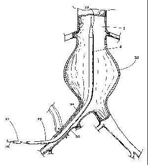
Hereinafter described is a bifurcated endovascular graft
1S0 and the method of insertion thereof for repair of abdominal
aortic aneurysm. Bifurcated graft insertion system 160 comprises
prosthesis 170 (graft/stent combination), prosthesis delivery
system 186, distal limb control system 190, distal stmt insertion
device 140, distal limb straightening device 130, and twist
preventing catheter 120. Many features of-the introduces system
and the prosthesis are to be found in the various embodiments of
the tubular graft insertion system. The others are unique to the
bifurcated graft.
The prosthesis comprises a graft and one or more stents.
Stents occupy the lumen of the graft orifices. Stems expand the
graft and fix it in position.
All stem s are of the self-expanding (Gianturco) type of
which a segment 201is depicted in FIG. 21. A complete loop of
wire is bent back and forth to form a crown or wheel with recurved ,
points 202 between straight limbs 203. The length and number of
limbs vary depending on the materials, the size of the vessel to
be grafted, and the size constraints of the introduces system.
However, the resting (non-deformed) diameter of a scent always
exceeds the diameter of the vessels to be grafted. Cranial stents
CA 02212286 1997-08-OS
WO 96/24308 PCT/LTS96/01550
- 29 -
are attached to the graft. Bends, protrusions or other surface
irregularities on the stems are used as a point of attachment
204. Protrusions may take the form of catheters or wires, which
may be glued, soldered, or brazed to the stent. All cranial
stents bear barbs 205. These sharp metal barbs project outward
from the surface of the stmt. The barb points caudally,
cranially, or in both directions. They are soldered, brazed or
glued to a stmt at any point. The number of barbs is variable.
Caudal stents are used with and without barbs.
Depicted in FIG. 22 is bifurcated graft 206 having a
cranial orifice 207 and at least two caudal orifices 208 and 209.
The graft resembles trousers. The graft includes a main body 250
and caudal limbs 210 and 213 extending therefrom. Main body 250
includes main bore 251 extending longitudinally therein and having
cranial orifice 207. Caudal limb 210 includes bore 252 extending
longitudinally therein, communicating with main bore 251, and
having caudal orifice 209. Caudal limb 213 includes bore 253
extending longitudinally therein, communicating with main bore
251, and having caudal orifice 208.
Grafts are knitted or woven in one piece from a durable
yarn such as polyester. There are no seams. An element of
elasticity may be incorporated as a property of the fabric or by
subsequent treatments such as crimping. The dimensions of the
graft vary according to the dimensions of the infra-renal aorta
and the common iliac arteries. In each patient a graft will be
selected that has diameters that exceed those of the recipient
vessels.
In the majority of cases it is important to preserve blood
flow through the internal iliac arteries. Therefore, most grafts
will be of such a length that caudal orifices 208 and 209 lie in
the common iliac arteries. An alternative embodiment uses grafts
that extend through the entire common and external iliac arteries
to exit the arterial tree via the femoral arteries. The caudal
limb of such a graft may be perforated or constructed of very
porous material to permit continued perfusion of the internal
iliac artery by leakage.
CA 02212286 1997-08-OS
WO 96/24308 PCT/US96/01550
- 30 -
Contralateral graft limb 210 on the side opposite to the
side of-insertion is marked with radio-opaque lines or imageable
markers 211 and 212. These lines are woven into the cloth of the
graft or applied after weaving. The lines may be continuous or
interrupted. These lines or markers need be only imageable with
any commercially available medical imaging equipment such as x-
rays, CT, MRI, or the like. The radio-opaque line is a fine wire
or chain of inert metal. Alternatively, the line is incorporated
into an inert paint or plastic-. The ipsilateral graft limb 213
needs only at least two radio-opaque markers 214 and 215 at caudal
orifice 208.
Prosthesis delivery system 180 comprises central carrier
216 and co-axial introduces sheath 217. The introduces sheath has
a constant diameter and wall thickness. The internal diameter of
the sheath corresponds to the external diameter of the central
carrier along two regions. One region is located caudally at
carrier shaft 218, and the other region is located cranially at
carrier head 219. In between these two regions is much narrower
carrier stem region 220.
The introduces sheath is a thin-walled, large-bore
catheter made of flexible, inert plastic with a low coefficient
of friction. The wall of the sheath incorporates mechanisms to
resist kinking (such as an internal wrap of metal wire). The
sheath is of constant diameter and wall thickness, except at
cranial orifice 223 where external surface 221 of the sheath
tapers to meet outer surface 222 of carrier head 219 in a smooth
transition as depicted in the preferred and alternative
embodiments of FIGS. 24 and 25. Caudal end 224 of the sheath as
depicted inFIG. 26 includes a hemostatic seal 225, which engages
outer surface 225 of the carrier shaft 218. The seal incorporates
a well-known lock 227 to grip the carrier shaft 226 tightly during .
introduction and prevent premature exposure of prosthesis 228.
The length of the sheath depends on the length of the central ,
carrier. The sheath must cover the entire -carrier stem and
overlap portions ofthe carrier head and the carrier shaft.
CA 02212286 1997-08-OS
WO 96/24308 PCT/US96/01550
- 31 -
As depicted in FIGS. 26 and 27, central carrier 216
includes inner catheter 229 and a co-axial outer catheter 230.
The inner catheter is of constant diameter and wall thickness.
Caudal end 231 of the inner catheter has an injection port 232.
Outer catheter 230 has a more complicated construction. Internal
lumen 233 matches the outer diameter of inner catheter 229, but
the outer diameter of the outer catheter varies. Distally, the
outer diameter corresponds to the inner diameter of the introducer
sheath as depicted in the embodiment of FIG-. 24. This segment of
the outer catheter is carrier head 219. Another small dilation
234 as depicted in FIG. 25 is immediately distal to the end of
introducer sheath 217, to further enhance the smooth transition
from carrier head 219 to sheath 217.
The internal diameter ofthe introducer sheath about the
caudal end thereof also matches the external diameter of the
caudal segment of carrier shaft 218. The narrower segment of the
central carrier between carrier head 219 and carrier shaft 218 is
carrier stem 220. During insertion, prosthesis 228 and its
associated catheter systems_are compressed into the space between
introducer sheath 217 and carrier stem 220.
As depicted in FIG. 23, two pairs of holes 235 and 236
traverse theouter catheter of the carrier stem, one pair at each
end of prosthesis 228. As depicted in FIG. 27, small loops of
suture 237 and 238 wind around inner catheter 229 at this point,
entering and exiting the lumen of outer catheter 230 through the
holes. These sutures, as well as suture loops 239 and 240, also
traverse some part of prosthesis 228, thereby attaching both ends
of the prosthesis to the central carrier. Loops 237-240 (and the
prosthesis) are released by removal of inner catheter 229. It is
important that the two loops of each set do not cross, otherwise
the resulting linkage will prevent release from the central
carrier despite removal of the inner catheter.
As depicted in FIG. 26, caudal end 241 of inner and outer
catheters 229 and 230 has a short flexible extension (with
dimensions and structure similar to carrier stem 220) . Both inner
and outer catheters have injection ports 232 and 242,
CA 02212286 1997-08-OS
WO 96/24308 PCT/US96/01550
- 32 -
respectively, at the caudal end of this extension. The injection
ports may be locked together with well-known lock 243 to prevent
premature removal of. the inner catheter.
As depicted in FIG. 23, cranial end 244 of the carrier
shaft (or the caudal end of carrier stem 220) includes annular
groove 245 for attachment of the catheters and sutures.
The diameter of carrier head 219 and shaft 218 are
determined by the diameter of introducer sheath217, which in turn
is dictated by the volume of the prosthesis. The minimum length
of the carrier stem is the distance from the proximal end of the
aneurysm to the skin of the groin. The maximum length of the
carrier shaft is the length of the introducer sheath (which must
exceed the length of the carrier stem). Therefore, central
carrier 216 is at least twice as long as the iliac artery and
aneurysm combined.
The mechanisms of caudal limb control will now be
described. All caudal limb control mechanisms extend from caudal
ends of limbs 210 and 213 of graft 206 to the level of the skin.
Caudal limb control mechanisms take the form of detachable tubular
extensions 246 and 247 of the graft as depicted in FIGS 28 and 29,
or, alternatively, combinations of catheters and/or sutures a.s
depicted in FIGs. 32-35. Both mechanisms must be amenable to
controlled release from the graft by manipulations of the caudal
end thereof which extends outside the body.
As depicted in FIG. 28, tubular extensions 246 and 247 are
sutured to the respective caudal ends of limbs 213 and 210 of
graft 206 by chain stitches 248 and 249, which unravel when cut.
Theses chain stitches are anchored by respective locking stitches
250 and 251. An alternative mechanism depicted in FIG. 29
involves loops of suture 252 and 253 that pass along the wall of
respective tubular extensions 246 and 247 to the junction with .
graft 206.
Alternatively, as depictedin FIG. 30, a single loop of
suture material 254 is used as the primary means of applying
traction to one point on the end of the caudal limb 210.
Attachment to multiple points on the end of caudal limb 210 is
CA 02212286 1997-08-OS
WO 96/24308 PCT/US96/01550
- 33 -
depicted in FIG. 31. When the one side of caudal limb control
suture 154 is cut, traction on the other side pulls the end of the
suture through the graft and out of the body. Enclosing the
suture in catheter 255 reduces the chances of inadvertent _
tangling. Side ports 256 on catheter 255 in FIG. 32 and multiple
side ports 257 and 258 on catheter 255 in FIG. 33 allow traction
to be applied to more then one point on the graft without
necessarily approximating the wall of limb 210. Knot 259 ensures
that suture 254 comes out with catheter 255 when the ends are-
freed by dividing both sides ofthe loop. Catheter/suture
combinations can also serve more than one function, because the
tension is only transmitted through shortest suture 260 as
depicted in FIG. 34. Traction on catheter 255 does not tighten
suture 261 until suture 260 is cut.
However, the two functions of limb control and guided
access to the graft lumen can only be performed simultaneously if
they are performed by separate catheters. FIG. 35 depicts caudal
limb control catheter 255 of contralateral limb 210. Caudal limb
control system 262 includes catheter 255 and suture 263.
As depicted in FIG. 36, guided access to the caudal lumen
of contralateral limb 210 is provided by a catheter 264 which is
moored to the central carrier a.n the same manner as loops 237 and
238 on the prosthesis. Contralateral lumen access guidance system
265 becomes tense and inflexible when traction is applied to its -
outer end. When tense, it functions as a guide wire within the
lumen of the stmt insertion device 140 as depicted in FIG. 39.
Contralateral limb access guidance system 265 is released from
central carrier 216 when inner catheter 229 is removed. Mooring
loop 266 is attached to the end of the catheter or passes through
its lumen to the caudal end (where a knot prevents suture
retraction). Sutures that are tied through side holes 267 in the
catheter have a tendency to pull out when tension is applied
unless the suture also encircles part of the catheter to
distribute traction more evenly as depicted in FIG. 37.
As depicted in FIG. 38, access to the lumen of the
ipsilateral limb 213 is guided by the same wire that is used for
CA 02212286 1997-08-OS
WO 96/24308 PCT/US96/01550
- 34 -
angiography and for insertion of the delivery system. If traction
is to be maintained during insertion of a stent on the ipsilateral
side, a caudal litiib control catheter 255 is also required on
ipsilateral distal limb 213.
The orientation of the contralateral- limb (and associated
catheters) to the carrier must be constant, because any twists are
subsequently reproduced in the relative orientation of the two
distal limbs. As an additional precaution, the location of
contralateral limb 210 is marked on the outside of the delivery
system.
Catheters may be made of any plastic that is flexible yet
strong enough to hold sutures with extreme thin-walled
construction. All sutures should be strong yet fine enough to
pass through small catheters. They should also have a low
coefficient of friction, to enhance removal at the end of the
procedure. Many monofilament and coated multifilament sutures
satisfy these criteria. Catheters must be long enough to be
accessible at the groin when the contralateral limb has been
pulled into position.
Depicted in FIG. 39 is caudal stem insertion device 140
including stmt pusher 271 and outer sheath 268. The basic
structure and function of the caudal stmt insertion device is
similar to prosthesis delivery system 180.
Caudal stent insertion device introducer sheath 268 is of
constant diameter and wall thickness, except at cranial orifice
269 where.the external surface of the sheath tapers to meet the
surface of pusher head 270 in a smooth transition. The sheath is
made of flexible, inert plastic with a low coefficient of
friction. The wall of the sheath may incorporate mechanisms to
resist linking (such as an internal wrap of metal wire). At the
cranial end of stem pusher 271 is pusher head 270, which has an
external diameter that matches the internal diameter of the
introducer sheath. Pusher shaft 272 also matches the diameter of ,
the introducer sheath. Between the two is a narrow pusher stem
273, which passes through the center of caudal stem 275.
CA 02212286 1997-08-OS
WO 96/24308 PCT/US96/01550
- 35 -
Depicted in FIG. 40 is contralateral limb straightening
device 130 for orienting the position of contralateral limb 210
of graft 206. Translocation of the contralateral limb of the
bifurcated graft can produce twists. Straightening device 130 a.s
advanced over the distal limb control system onto the end of the
distal limb and rotated to remove twists. The contralateral limb
straightening device is a catheter or small gauge dilator with a
fish-mouth split at cranial end 274. The terminal split occupies
a plane that also contains the long axis of the device. When
traction is applied to suture 254 of the contralateral distal limb
control system, the suture is pulled into the catheter
approximating the two walls of the graft. The flattened
contralateral limb then slides into the slot of the advancing
straightening device. Torsion on the device is transmitted to the
end of the graft to straighten any twists.
Depicted in FIG. 41 is an alternative limb straightening
device 131 designed primarily for use with the system of tubular
graft extensions 246 and 247. The alternative device is a dilator
with a soft rounded tip and_a bulbous dilation 132 at cranial end
133. The dilatation is pushed into a narrowing of the tubular
extension, which is maintained under tension by traction on the
caudal end. The tight fit enables torsional forces to be
transmitted to the graft through friction at the surface of the
dilatation. In the absence of the tubular graft extensions, the
alternative limb straightening device is advanced over
contralateral lumen access guidance system 265. The dilatation
then engages the inner aspect of the distal limb orifice 209.
Alternatively, the dilatation may take the form of a balloon,
which is inflated inside caudal limb 210. Whatever form the
straightener takes, it must be long enough to reach the end of the
caudal limb from the femoral arteriotomy. The diamete-r is
variable, depending on the mechanism of graft attachment. The
device must be flexible, yet resist deformation when torsional
stresses are applied to the caudal end. '
Depicted in FIG. 42 is a sectioned view twist-preventing,
double lumen catheter 120. This soft, flexible catheter has two
CA 02212286 1997-08-OS
WO 96/24308 PCT/US96/01550
- 36 - -
lumens 121 and 122. One is occupied by the cross femoral
catheter, while the other is occupied by the angiographic catheter
(or wire). Cranial end 123 is slightly tapered for ease of
insertion. The catheter resists torsion so that the relative
orientation of the two lumens is maintained. The twist-
preventing, double lumen catheter is inserted to the point where
the two catheters diverge, one passing through the aneurysm to the
proximal aorta, the other crossing to the opposite iliac artery.
The method for inserting the prosthesis and use of the
insertion instruments is hereinafter described. Patients are
selected for-this procedure on the basis of radiographic imaging
(including angiography) and general physical condition.
The patient is placed in the supine position on a
radiolucent operating table. Access to the arterial tree may be
obtained by surgical isolation of the femoral vessels in the
groin. Alternatively, the insertion may be performed through
large introducer sheaths placed by pe-rcutaneous techniques. In
the open technique, silastic bands around the common femoral
arteries provide proximal hemostasis, while non-crushing clamps
provide distal hemostasis. Most patients will be anticoagulated
with heparin prior to the interruption of the circulation to the
legs.
Insertion is guided by fluoroscopy. When available,
digital subtraction processing enhances fluoroscopic images and
is usedto record angiograms. Another useful feature of digital
subtraction imaging equipment is the "roadmapping" function, which
combine real time fluoroscopic images with static angiograms. The
composite image facilitates guidance of the apparatus through the
vascular tree.
An initial angiogram is performed to provide the reference
points that guide insertion. Angiography will frequently have
been performed as part of the selection procedure, in which case
measurements determining graft size and form will already have
been taken. After initial angiography the catheter is removed,
leaving the guide wire in place.
CA 02212286 1997-08-OS
WO 96/24308 PCT/US96101550
- 37 -
A wire, suture, catheter or tape is passed from one
femoral artery to the other. In one method depicted in FIGs. 48
and 49, a Dormierbasket 280 is passed up the ipsilateral femoral
artery 30 and opened over the contralateral iliac artery orifice
281. A catheter or guide wire 282 is threaded up the opposite
femoral artery 96 through the wires of the Dormier basket. The
basket is then closed on the guide wire and withdrawn pulling the
guide wire through femoral access site 283. The procedure is -
swift and relatively atraumatic, especially if a very soft,
flexible catheter is used. An alternative method involves
fluoroscopically guided manipulation of the curved tip of a
catheter/guide wire system from one iliac artery into the other.
Care must be taken to avoid winding the angiographic
catheter around the cross femoral system. This may be
accomplished by inserting the angiographic catheter (or wire)
through one lumen of a double lumen, twist-preventing catheter 120
as depicted in FIG. 42, while the other lumen is occupied by the
cross femoral system (or vice versa).
The introducer system is threaded over the same guide wire
that occupied the lumen of the angiographic catheter.
Fluoroscopic visualization is relatively easy because all
components of the apparatus (except the fabric of the graft) are
radio-opaque. The position of the prosthesis is controlled during
extrusion by manipulation of the central carrier. When the
introducer sheath is withdrawn, the stems expand, opening the
graft.and fixing it in position. Further withdrawal of the
introducer sheath 217 exposes the caudal limb control mechanisms
and their attachment to central carrier 216. The caudal limb
control mechanisms, such as suture loops 237 and 238 or other
catheters, sutures, or tubular graft extensions, -are attached to
the cross femoral system (catheter, suture, tape or-guide wire)
using sutures, tape or clips. Traction on the cross femoral
system (at the contralateral groin) pulls the contralateral limb
210 into the contralateral iliac artery.
The contralateral limb 210 is sometimes twisted after
translocation to the contralateral iliac artery. Twisting is
CA 02212286 1997-08-OS
WO 96!24308 PCT/US96/01550
- 38 -
revealed by the fluoroscopic appearance of the radio-opaque lines
211 and 212. The contralateral limb control mechanism such as
suture loops 237 and 238 is used to apply traction to other
contralateral limb 210 and pull it onto the advancing
contralateral limb straightening device 130 or 131. Straightening
is guided by the fluoroscopic appearance and the character of the
femoral arterial pulse and blood flow.
Stems are occasionally required to prevent retrograde
leakage of blood around the caudal limbs 210 and 211 back into the
aneurysm. The distal stmt insertion device may be passed through
the lumen of a tubular graft extension 247. Alternatively, the
stem insertion device is passed over a guide wire or over
contralateral lumen access guidance system 265. Whichever method
is used, it is usually necessary to maintain traction on the
caudal limbs using the caudal limb control mechanism. Insertion
of the ipsilateral stent cannot be performed until the delivery
system has been removed_
The prosthesis 228 is released from the central carrier
216 by removal of the inner catheter 229. It is important to
replace the inner catheter and advance the guide wire through the
centrallumen before removing the delivery system, because the
wire is needed to-guide the scent insertion device into the lumen
of the ipsilateral caudal limb 213. After stmt insertion the
wire is needed again to guide insertion o_f a catheter for
completion angiography. If angiographic appearances are
satisfactory, the catheters are removed, the arteries repaired,
and the wounds closed-
Depicted in FIG. 43 is transluminal arrangement 350 for
positioning prosthesis assembly 228 at a particular position in
a bifurcated lumen. As depicted in FIGS. 48 and 49, bifurcated
lumen 284 is located in aorta 2 with common iliac arteries 34 and
eXtending distally therefrom. Aortic aneurysm 20 is located
just proximal the common iliac-arteries 34 and 35. Aortic lumen
285 forms the main lumen, whereas common iliac lumens 286 and 287
35 communicating with the main lumen form the branch lumens.
CA 02212286 1997-08-OS
WO 96/24308 PCT/LTS96/01550
- 39 -
Prosthesis assembly 228 depicted in FIG. 43 includes
bifurcated endovascular graft 206, main spring assembly 301, and
limb spring assemblies 302 and 303 (not shown) positioned in
respective stmt boots 304 and 305. Main spring assembly 301, as
well as prosthesis assembly 228, is contained in main container
sheath 217 which is, for example, a polytetrafluoroethylene tube.
Bifurcated endovascular graft 206 includes main body 250 with
ipsilateral limb 213 and contralateral limb 210 extending
therefrom and partially over the tops of respective stmt boots
304 and 305.
As previously described with respect to FIG: 22, main body
250 includes main bore 251 extending longitudinally therein with
cranial orifice 207. Contralateral limb bore 252 and ipsilat-eral
limb bore 253 communicate with main bore 251 and extend
longitudinally through respective contralateral limb 210 and
ipsilateral limb 213. Contralateral limb 210 has caudal orifice -
209, whereas ipsilateral limb 213 has caudal orifice 208. Main
spring assembly 301 is positioned through cranial orifice 207 and
into bore 251 of the main -body for radially expanding the main
body of the graft to substantially conform the main body of the -
graft on the interior wall of main lumen 285. Main spring
assembly 301 expands from its compressed state, as shown in
FIG. 43, when the prosthesis assembly is positioned in the
bifurcated lumen and released from container sheath 217.
Transluminal arrangement 350 includes outer sheath 217 for
containing main spring assembly 301 in a compressed state, stmt
boot sheath 304 for containing ipsilateral spring assembly in a
compressed state; stmt boot sheath 305 for containing
contralateral spring assembly in a compressed state; and main
retainer assembly 351 positioned in the main and ipsilateral bores
of the graft for retaining prosthesis assembly 228 in the
bifurcated lumen while the outer sheath is withdrawn from the
prosthesis assembly releasing the main spring assembly from its
compressed state.
35- Similar to previously described central carrier 216, main
retainer assembly comprises elongated member 352 having dilator
CA 02212286 1997-08-OS
WO 96/24308 PCTlUS96/01550
- 40 - -
head 353 at the distal end thereof. The dilator head serves to
facilitate penetration of the transluminal arrangement within the
bifurcated lumen and minimizes deleterious blood flow during
positioning of the transluminal arrangement. Elongated member 352
also includes an intermediate carrier stem region including outer
catheter 318, hollow connector sleeve 354 with lateral apertures
355 and 356 formed therein, and inner catheter 319 extending
longitudinally through the elongated member including the outer
catheter and connector sleeve. Connector sleeve 354 interconnects
segments of outer catheter 318 and facilitates as to permit
attachment of sutures 357 and 358 to inner catheter 319 through
respective apertures 355 and 356. One end of attachment sutures
357 and 358 are tied around the outer surface of outer catheter
318, whereas other end of the sutures are tied around the outer
surface of inner catheter 319 through the connector sleeve
apertures. Attachment sutures 357 and 358 are looped through the
opposite sides of main spring assembly 301 for retaining the
prosthesis assembly in the bifurcated lumen while outer sheath 217
is withdrawn from the prosthesis assembly releasing the main
spring assembly from its compressed state. The outer sheath
includes longitudinal bore 3.59 in which the prosthesis assembly
is positioned during insertion of the assembly into the bifurcated
lumen: Attachment sutures 357 and 358 form a contraction assembly
for temporarily pulling main spring assembly 301 to a compressed
state when prosthesis assembly 228 is positioned within main outer
sheath 217. The distal end of the outer sheath is positioned next
to the proximal end of dilator head 353 to. facilitate easy
insertion of the transluminal arrangement into the bifurcated
lumen.
Elongated member 352 also includes a carrier shaft region
360 similar to carrier shaft region 218 of which annular recess
309 is formed therein.
FIG. 44 depicts a partially sectioned side view of
ipsilateral limb spring assembly 302 in a compressed state. The
spring assembly is attached to the inside of ipsilateral limb 213
via sutures 315 and 316 and is contained in stmt boot sheath 304.
CA 02212286 1997-08-OS
WO 96/24308 PCT/US96/01550
- 41 -
When the prosthesis assembly is properly positioned about aneurysm
20, ipsilateral spring assembly 302 is released from its
compressed state to radially expand limb 213 and substantially
conform the limb to the interior wall of common iliac artery 34.
Stent boot sheath 304 forms a container for containing ipsilateral
spring assembly 302 in a compressed state. Suture 314 is
temporarily attached to ipsilateral spring assembly 302 for
retaining the spring assembly in the stmt boot sheath during
positioning of the prosthesis assembly in the bifurcated lumen.
Suture 314 forms a release mechanism for releasing the ipsilateral
spring assembly when the prosthesis assembly is positioned in the
bifurcated lumen and, in particular, when ipsilateral limb 213 is
properly positioned in common iliac artery 34. After suture 314
is detached from the ipsilateral spring assembly, stmt boot 304
is withdrawn from the spring assembly, releasing it from its
compressed state. When released from its compressed state,
ipsilateral spring assembly 302 radially expands graft limb 213
to substantially conform the limb on an interior wall of iliac
artery lumen 286.
Stent boot 304 is a tubular container such as a sheath or
short piece of polytetrafluoroethylene tube fnr containing
ipsilateral spring assembly 302 therein in a compressed state.
Ipsilateral spring assembly 302 is attached along its midsection
to contralateral graft limb 213 inside limb bore 253 with sutures
315-and 316. Attachment sutures 315 and 316 are placed cranially
from caudal orifice 208 to allow the caudal end of the graft limb
to extend over the top of stmt boot 304. Attachment sutures 314
and 317 are temporarily attached to ipsilateral spring assembly
302 for retaining the spring assembly in stem boot 304. One end
of attachment sutures 314 and 317 are tied around outer catheter
318 of the transluminal positioning arrangement, whereas the other
end of the sutures are tied around inner catheter 319 through
apertures 320 and 321 of connector sleeve 322. The inner catheter
of the positioning arrangement forms part of a release mechanism
that is temporarily attached to the ipsilateral spring assembly
for releasing attachment sutures 314 and 317. Attachment sutures
CA 02212286 1997-08-OS
WO 96/24308 PCT/US96/01550
- 42 -
314 and 317 and inner catheter 319 form-a--retainer mechanism for
retaining ipsilateral spring assembly 302 in stent boot 304.
Connector sleeve 322 is a short length of tubing having apertures
320 and 319 formed laterally therethrough. The connector sleeve
has an inner diameter approximating the outer diameter of outer
catheter 318. Outer catheter 318 is cut and inserted into the
opposite ends of the connector sleeve and bonded thereto using,
for example, medical grade adhesive. Inner catheter 319 passes
through the passageway of the connector sleeve and outer catheter
for retaining attachment sutures through the lateral apertures in
the sleeve.
FIG. 45 depicts a partially sectioned side view of
contralateral spring assembly 304, attached to the inside of
contralateral limb 210, and contained in stmt boot 305. Limb
control catheter 255 is attached proximally to stent boot 305 and
has suture 254 extending longitudinally through catheter lumen
306. Suture 254 is temporarily attached to contralateral spring
assembly for retaining the spring assembly in the stent boot
during positioning of the prosthesis assembly in the bifurcated
lumen. Suture 254 forms a release mechanism for releasing the
contralateral spring assembly when the prosthesis assembly is
positionedin the bifurcatedlumen and, in particular, when
contralateral limb 210 is positioned in common iliac artery 35.
After suture 254 is detached from the contralateral spring
assembly, stmt-boot 305 is withdrawn from the spring assembly,
releasing it from its compressed state. When released from its
compressed state, contralateral spring assembly 303 radially
expands limb 210 to substantially conform the limb on an interior
wall of iliac artery lumen 287. Limb control catheter 255 is a
commercially available copolymer tube to which stmt boot 305 is
integrally formed or attached thereto, for example, using medical
grade adhesive. Stent boot 305 is a tubular container such as a
short piece of polytetrafluoroethylene tube for containing
contralateral spring assembly 303 therein in a compressed state.
Contralateral spring assembly 303 is attached along its midsection
to contralateral graft limb 210 inside limb bore 255 with sutures
CA 02212286 1997-08-OS
WO 96/24308 PCT1US96/01550
- 43 -
307 and 308. Attachment sutures 307 and 308 are placed cranially
from caudal orifice 209 to allow the caudal end of the graft limb
to extend over the top of stmt boot 305. Contralateral spring
assembly 303 can include one or more barbs for digging into the
vessel wall and more securely anchoring the prosthesis assembly.
However, the contralateral spring assembly can be used with or
without these barbs. Retainer suture 254 is temporarily attached
to carrier shaft annular recess 309 via suture 310.
Depicted in FIG. 50 is an improvement to transluminal
arrangement 350 for.positioning prosthesis assembly 228 at a
particular position in a bifurcated lumen. As previously
described with respect to FIGS. 43-45, transluminal arrangement -
350 includes a main or outer sheath 217 for containing main spring
assembly 301 in a compressed state, a stmt boot sheath 304 for
containing ipsilateral spring assembly 302 in a compressed state,
and stent boot sheath 305 for containing a contralateral spring
assembly 303 in a compressed state. The transluminal arrangement
also includes main retainer assembly 351 positioned in the main
and ipsilateral bores of the graft for retaining the prosthesis
assembly in the bifurcated lumen while outer sheath 217 is
withdrawn from the prosthesis assembly. As a result, the main
spring assembly is released from its collapsed state. However, -
a problemwith transluminal arrangement 350 of FIGS. 43-45 is that
the prosthesis assembly 228 and, in particular, main spring
assembly 301 can be pulled caudally and undesirably repositioned -
when main retainer assembly 351 and, in particular, elongated
member 352 is pulled caudally to release- ipsilateral spring
assembly 302 from stent boot sheath 304.
In order to overcome this problem, the stmt boot sheath
of the transluminal arrangement has been improved to include
tubular sheath 362. The tubular sheath includes a longitudinal
bore 363 and is slidably and longitudinally positioned around
elongated member 352 and in particular outer catheter 318. Bore
363 of the tubular sheath approximates the diameter of elongated
cylindrical member 352 to minimize blood flow therethrough, but
allows the sheath to slide along the elongated cylindrical member
CA 02212286 1997-08-OS
WO 96/24308 PCT/LTS96/01550
- 44 -
to release ipsilateral spring assembly 302 of the prosthesis
assembly. The bore of the tubular sheath at and in the vicinity
of cranial end 364 of the tubular sheath is enlarged to receive
caudal end 372 of the prosthesis assembly and, in particular,
ipsilateral spring assembly 302 positioned thereat. To
radiographically visualize tubular sheath 364 during the
prosthesis placement procedure, the tubular sheath includes a
radiopaque material such as a polyether block amide nylon 12
elastomer.
The improvement of transluminal arrangement 350 further
includes slit 365 extending longitudinally in tubular sheath 362
from caudal end 366 thereof. In order to maintain the fixed
relative position of tubular sheath 362 with respect to outer
catheter 318, another improvement includes a plurality of annular
ridges and grooves 369, that are positioned adjacent caudal end
369 of the tubular sheath. A fastenersuch as suture material 368
is tied around the tubular sheath and in annular groove 367 of the
plurality. The tied suture material in annular groove 367
maintains longitudinal slit_365 in a closed position around outer
catheter 318. When the physician desires to expand ipsilateral
spring assembly 302, tied suture material 368 is cut, thus
allowing the caudal end of the tubular sheath to be spread apart
along the longitudinalslit 365.
FIG. 52 depicts caudal end 366 of tubular sheath 362 split
apart along longitudinal slit 365 with outer catheter 318
extending through the slit. As a result, tubular sheath 362 can
be slid caudally along outer catheter318 to release ipsilateral
spring assembly 302. This advantageously permits the release of
ipsilateral spring assembly 302 without undue tension on the
prosthesis assembly and in particular main spring assembly 301.
Main retainer assembly 351 is maintained in a fixed relative
position, which in turn maintains the position of the prosthesis
assembly with mooring loops 357 and 358 looped around main spring
assembly 301 and mooring loops 314 and 317 positioned around
ipsilateral spring assembly 302. These mooring loops are
positioned through elongated member 352, which is maintained in
CA 02212286 1997-08-OS
WO 96/24308 PCT/LTS96/01550
- 45 -
a fixed relative position when sliding tubular sheath 362
thereover. As a result, the prosthesis assembly is maintained at
the desired position in the aorta and one of the iliacs without
having to reposition the prosthesis assembly due to movement of
the assembly during the placement procedure.
Still another improvement in transluminal arrangement 350
is the inclusion of longitudinal markers 370 and 371 positioned
on carriershaft region 360 and dilator head 351, respectively. .
These longitudinal markers positioned on elongated member 352
provide the physician with a visual indication of the orientation
of prosthesis assembly 228 during the surgical placement
procedure. These longitudinal markers are depicted in FIGS. 50
and 52. To further stabilize the position of main spring assembly
301 and ipsilateral spring assembly 302, the previously described
circular apertures 355, 356, 320 and 321 have been replaced with
closely spaced transverse slots 374, 375, 372 and 373,
respectively. These closely spaced slots more readily maintain
the equal lengths of mooring loops 357, 358, 314 and 317 so as to
maintain more even retention pressure on main spring assembly 301
and ipsilateral spring assembly 302. As a result, the prosthesis
assembly 228 is better maintained in a fixed relative position
during the placement procedure with undesirable movement being
minimized.
FIG. 46 depicts a partially sectioned side view of stmt
boot 305 attached to control limb delivery catheter 255 which is
positioned in longitudinal lumen 311 of contralateral limb
straightening device 130. A plurality of longitudinal splines 312
is formed in the proximal end of stmt boot 305 to match a
corresponding plurality of splines 313 positioned around the
distal end -of straightening device lumen 311. The mating splines
engage each other to rotate the stent boot and contralateral limb
for proper positioning within the common iliac artery.Markers
are positioned in the graft limbs for radiographic imaging. _
FIG. 47 depicts prosthesis assembly 228 positioned in
bifurcated lumen 284 of aorta 2 and common iliac arteries 34 and
35. Main spring assembly 301 has been released from its
CA 02212286 1997-08-OS
WO 96/24308 PCT/US96/01550
- 46 -
compressed state and radially expanded main body 250 of the graft
to substantially conform the main body of the graft on the
interior wall of main lumen 285 of the aorta. Similarly,
ipsilateral spring assembly 302 has been released from its
compressed state and elongated member 352 and radially expanded
ipsilateral limb 213 of the graft to substantially conform the
ipsilateral limb on an interior wall oflumen 286 of common iliac
artery 34. Contralateral spring assembly 303 has been released
from its compressed state and radially expanded contralateral limb
210 to substantially conform the contralateral limb of the graft
on aninterior wall of lumen 287 of common iliac artery 35.
Control limb delivery catheter_255 and stent boot 305 have been
withdrawn from the contralateral spring assembly allowing it to
expand the contralateral limb of the graft.-
The method of positioning the prosthesis assembly at the
particular position in bifurcate-d lumen 284 includes providing
first and second access sites 283 and 361 to branch lumens 286 and
287 in respective common iliac arteries 34 and 35 in a well-known
manner. As previously described with respect to FIGS. 48 and 49,
the guide is provided between access sites 283 and 361 via the
branch lumens. Transluminal arrangement 350 including retainer
assembly 351, elongated member 352, and prosthesis assembly 228
attached thereto are positioned within the bifurcated lumen.
Outer sleeve 217 is withdrawn from the prosthesis assembly, and
control limb delivery catheter 255 guides the contralateral limb
of the graft into branch lumen 287 of iliac artery 35. The
attachment sutures are released from themain, ipsilateral and
contralateral spring assemblies positioning the prosthesis in the
bifurcated lumen. Stent boots 304 and 305 are removed from their
respective spring assemblies during withdrawal of retainer
assembly 352 and control limb delivery catheter 255.
The transluminal arrangement for positioning a prosthesis
assembly at a particular position in a bifurcated lumen and the
method of placement has been illustrated and described in the
drawing- and the foregoing description, the same is to be
considered illustrative and not restrictive in character. It is
CA 02212286 1997-08-OS
WO 96/24308 PCT/L1S96/01550
- 47 -
to be understood that only the preferred embodiment has been shown
and that all changes and modifications that come within the scope
of the claims are to be protected. In particular, stent boots 304
and 305 have been referred to as containers or sheaths and are
typically formed from a thin polytetrafluoroethylene tube of
material. The stmt boots are either affixed to the outer
catheter of the retainer assembly or slidable thereon. Similarly,
stmt boot 304 is attached using, for example, medical grade
adhesive, are slidable at the end of the control delivery
catheter. Outer sheath 217 is also a container or sheath of, for
example, a semi-rigid polytetrafluoroethylene material for
containing the prosthesis assembly therein. The spring assemblies
are of the Gianturco Z-stem type as previously described with or
without barbs for more securely affixing the prosthesis assembly
to- the wall of the bifurcated lumen. Any type of radially
expanding spring assembly or stmt is contemplated whether the
spring assembly or stmt is automatically expanded when released -
from a container or expanded with a dilator balloon and the like.