Language selection

Search

Patent 2212496 Summary

Third-party information liability

Some of the information on this Web page has been provided by external sources. The Government of Canada is not responsible for the accuracy, reliability or currency of the information supplied by external sources. Users wishing to rely upon this information should consult directly with the source of the information. Content provided by external sources is not subject to official languages, privacy and accessibility requirements.

Claims and Abstract availability

Any discrepancies in the text and image of the Claims and Abstract are due to differing posting times. Text of the Claims and Abstract are posted:

  • At the time the application is open to public inspection;
  • At the time of issue of the patent (grant).
(12) Patent: (11) CA 2212496
(54) English Title: A PROJECTILE HAVING FEATURES OF HIGH DEFORMABILITY ON IMPACT
(54) French Title: PROJECTILE TRES DEFORMABLE SUR IMPACT
Status: Expired and beyond the Period of Reversal
Bibliographic Data
(51) International Patent Classification (IPC):
  • F42B 12/74 (2006.01)
  • F42B 8/12 (2006.01)
  • F42B 8/14 (2006.01)
(72) Inventors :
  • BENVEGNU', CARLO (Italy)
(73) Owners :
  • FIOCCHI MUNIZIONI S.P.A.
(71) Applicants :
  • FIOCCHI MUNIZIONI S.P.A. (Italy)
(74) Agent: SMART & BIGGAR LP
(74) Associate agent:
(45) Issued: 2005-05-03
(22) Filed Date: 1997-08-06
(41) Open to Public Inspection: 1998-02-07
Examination requested: 2002-05-28
Availability of licence: N/A
Dedicated to the Public: N/A
(25) Language of filing: English

Patent Cooperation Treaty (PCT): No

(30) Application Priority Data:
Application No. Country/Territory Date
MI 96 A 001719 (Italy) 1996-08-07

Abstracts

English Abstract


A projectile for firearms has a body (11) consisting of a
plurality of disc-shaped elements (14) coaxially fitted in
a holding cup (15) forcedly filled therewith.


Claims

Note: Claims are shown in the official language in which they were submitted.

6
CLAIMS:
1. ~A target-shooting projectile for firearms,
comprising a body having a substantially cylindrical shaped
rear portion defining the rear end of the projectile, and a
coaxial front portion of ogive-shaped configuration defining
the front end of the projectile, and a plurality of disc-
shaped elements coaxially and forcedly fitted in said body,
said elements having curved, coaxially disposed center
portions thereof projecting toward one end of said
projectile.
2. ~A projectile as claimed in claim 1, characterized
in that the center portions of said disc-shaped elements
form thereon concave surfaces that are turned towards the
rear end of the projectile.
3. ~A projectile as claimed in claim 2, characterized
in that the center portions of said disc-shaped elements
have increasing curvatures towards the front end of the
projectile.
4. ~A projectile as claimed in claim 3, characterized
in that as the respective positions of the elements progress
towards the front end of the projectile, the center portions
of the disc-shaped elements have an increasingly growing
depth in the middle thereof for receiving central
projections of preceding disc-shaped elements.
5. ~A projectile as claimed in claim 1, characterized
in that the disc-shaped elements are made of deformable thin
iron plate.
6. ~A projectile as claimed in claim 3, characterized
in that said plurality of disc-shaped elements have the same
diameter on being fitted in said body, the projecting center

7
portions of the disc-shaped elements in said front portion
being obtained by reduction of the diameter of the front
portion of the body by forming.
7. ~A projectile as claimed in claim 1, characterized
in that it includes a portion of deformable material,
disposed at the front end of the projectile and covering the
disc-shaped elements.
8. ~A projectile as claimed in claim 7, characterized
in that the deformable portion is made of rubber or plastic
material.

Description

Note: Descriptions are shown in the official language in which they were submitted.


CA 02212496 1997-08-06
1
A PROJECTILE HAVING FEATURES OF HIGH DEFORMABILITY ON
IMPACT
The present invention relates to a projectile provided
with a structure enabling achievement of a great reduction
in damages and rebounds on impact against an obstacle.
This projectile is particularly adapted for. use in
shooting ranges.
In target-shooting projectiles, intended for use in rifle
ranges, the bullet must have features of high
deformability so as to avoid serious damages to be caused
to structures and objects placed behind or close to the
target, should the target be missed. In addition,
undesired reboundings of the projectile are to be avoided.
Far the purpose, projectiles made of lead have been used
for a long time, as the malleability of them enables the
kinetic energy transmitted to the obstacles on impact to
be greatly reduced.
However, use of lead projectiles at circumscribed areas,
such as rifle ranges, involves accumulation of great
amounts of this metal, which is highly polluting. In the
recent years the increased attention paid to problems
concerning environmental protection has made it desirable
to manufacture projectiles devoid of parts made of lead,
which however, at the same time, are provided with
features of high deformability on impact against rigid
obstacles.
A further drawback typical of lead projectiles consists in

CA 02212496 2004-08-30
73475-37
2
that, due to the weak hardness of the material, projectiles
on firing undergo a mechanical abrasive action by the
rifling system present on the inner surface of the barrel,
which involves removal of small metal amounts. Lead thus
removed in the long run causes an accumulation of metal
particles in said rifling system, which phenomenon, known as
"lead storage" of the barrel, brings about worsening of the
firearm performance.
It is a general object of the present invention to obviate
the above mentioned drawbacks by providing a projectile
having features of high deformability on impact against a
rigid obstacle, although it is not made of a particularly
soft material such as lead.
In view of the above object, in accordance with the
invention, there is provided a target-shooting projectile
for firearms, comprising a body having a substantially
cylindrical shaped rear portion defining the rear end of the
projectile, and a coaxial front portion of ogive-shaped
configuration defining the front end of the projectile, and
a plurality of disc-shaped elements coaxially and forcedly
fitted in said body, said elements having curved, coaxially
disposed center portions thereof projecting toward one end
of said projectile.
For better explaining the innovatory principles of the
present invention and the advantages it offers over the
known art, a possible embodiment thereof applying said
principles will be described in the following, by way of
non-limiting example, with the aid of the accompanying
drawings. In the drawings:
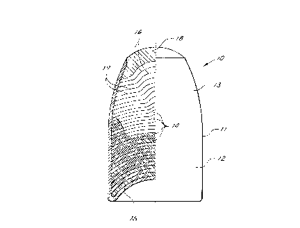
- Fig. 1 is a view partly in section of a projectile in

CA 02212496 2004-08-30
73475-37
2a
accordance with the invention during the step of fitting the
disc-shaped elements therein;
- Fig. 2 is a view similar to that in Fig. 1, referred to

CA 02212496 1997-08-06
3
a finished projectile.
With reference to the drawings, a projectile 10 comprises
a bullet body 11 having a rear portion 12 of substantially
cylindrical shape and a front portion 13 of an
ogive-shaped conformation.
According to the invention, body 11 consists of a
plurality of disc-shaped elements 14 coaxially fitted in a
holding cup 15 and superposed in an axial direction to the
projectile.
For graphic clarity purposes, in the accompanying drawings
the disc-shaped elements 14 are shown in section (section
lining) only at one portion of the body 11 itself, whereas
in the other areas only an outline thereof has been
reproduced.
The disc-shaped elements 14, that can be made of thin iron
plate for example so as to be deformable by themselves,
are advantageously packed within the cup 15 so that at
least one portion thereof has its concavity turned towards
the rear part of the projectile in order to increase the
packing steadiness.
The iron plate concavity can be obtained before packing of
them or, advantageously (as is apparent from a comparison
between Figs. 1 and 2), after packing, during the step of
farming the outer jacket 15.
When during the projectile working the cup 15 is given its
final shape, the disc-shaped elements 14 disposed in the
front portion of the projectile undergo a remarkable
curling up towards their centre, taking a configuration

CA 02212496 1997-08-06
4
where the central portions 16 thereof project forwardly
relative to the respective peripheral portions 17. This
helps in improving cohesion of the disc packing and the
ballistic steadiness of the projectile. In addition, the
energy absorption features on impact against an obstacle
are enhanced.
At the moment of firing and during the flight, the
projectile in accordance with the invention ballistically
behave like a traditional projectile.
On impact against a rigid obstacle, due to the innovative
configuration of the projectile, the unavoidable
deformation or breaking of the disc-holding cap 15, even
if of light value, makes the discs immediately free, so
that they can spread all around without causing further
damages. Actually, the kinetic energy of the projectile is
partly absorbed by the disc deformation and partly shared
out into negligible energy amounts transferred to the
individual discs being part of said plurality.
It is therefore apparent that a projectile envisaged in
accordance with the present invention achieves the
intended purposes, i.e. it enables the kinetic energy of
the projectile itself to be spread exactly on impact
without damages.
In addition, by use of the inventive projectile,
environmental damages resulting from employment of lead
projectiles are avoided. Finally, since cup 15 can be made
of a relatively hard material, there is an enhancement in
the sliding features of the projectile along the barrel.

CA 02212496 1997-08-06
Obviously, the above description of an embodiment applying
the innovatory principles of the invention is given for
purposes of illustration only and is not to be interpreted
as a limitation of the scope of the invention as herein
claimed.
For example, the disc-shaped elements 14, instead of being
of a uniform diameter, can have decreasing diameters
towards the front portion of the projectile. In this case,
when ogive-like tapering of the cup 15 is carried out,
deformation of the front discs shown in the figure will
not occur (or will occur to a lower degree). In addition,
the disc-shaped elements can optionally have particular
conformations adapted to create deformation chambers
between pairs of adjacent discs.
Finally, the projectile may be provided with a deformable
portion 18 consisting of a rubber or plastic element for
example, disposed at the front end of the projectile and
covering the disc-shaped elements 14. This portion enables
the perforating ability of the projectile to be decreased
and makes it easier to cause its disintegration on impact
and, in addition, it may represent an element of
identification of the projectile type.

Representative Drawing
A single figure which represents the drawing illustrating the invention.
Administrative Status

2024-08-01:As part of the Next Generation Patents (NGP) transition, the Canadian Patents Database (CPD) now contains a more detailed Event History, which replicates the Event Log of our new back-office solution.

Please note that "Inactive:" events refers to events no longer in use in our new back-office solution.

For a clearer understanding of the status of the application/patent presented on this page, the site Disclaimer , as well as the definitions for Patent , Event History , Maintenance Fee  and Payment History  should be consulted.

Event History

Description Date
Time Limit for Reversal Expired 2007-08-06
Letter Sent 2006-08-07
Inactive: IPC from MCD 2006-03-12
Grant by Issuance 2005-05-03
Inactive: Cover page published 2005-05-02
Inactive: Final fee received 2005-02-16
Pre-grant 2005-02-16
Notice of Allowance is Issued 2004-12-13
Letter Sent 2004-12-13
Notice of Allowance is Issued 2004-12-13
Inactive: Approved for allowance (AFA) 2004-11-01
Amendment Received - Voluntary Amendment 2004-08-30
Inactive: S.30(2) Rules - Examiner requisition 2004-06-17
Letter Sent 2002-07-23
Request for Examination Requirements Determined Compliant 2002-05-28
All Requirements for Examination Determined Compliant 2002-05-28
Request for Examination Received 2002-05-28
Application Published (Open to Public Inspection) 1998-02-07
Inactive: First IPC assigned 1997-11-07
Classification Modified 1997-11-07
Inactive: IPC assigned 1997-11-07
Inactive: Filing certificate - No RFE (English) 1997-10-14
Filing Requirements Determined Compliant 1997-10-14
Letter Sent 1997-10-14
Application Received - Regular National 1997-10-14

Abandonment History

There is no abandonment history.

Maintenance Fee

The last payment was received on 2004-07-15

Note : If the full payment has not been received on or before the date indicated, a further fee may be required which may be one of the following

  • the reinstatement fee;
  • the late payment fee; or
  • additional fee to reverse deemed expiry.

Please refer to the CIPO Patent Fees web page to see all current fee amounts.

Owners on Record

Note: Records showing the ownership history in alphabetical order.

Current Owners on Record
FIOCCHI MUNIZIONI S.P.A.
Past Owners on Record
CARLO BENVEGNU'
Past Owners that do not appear in the "Owners on Record" listing will appear in other documentation within the application.
Documents

To view selected files, please enter reCAPTCHA code :


To view images, click a link in the Document Description column. To download the documents, select one or more checkboxes in the first column and then click the "Download Selected in PDF format (Zip Archive)" or the "Download Selected as Single PDF" button.

List of published and non-published patent-specific documents on the CPD .

If you have any difficulty accessing content, you can call the Client Service Centre at 1-866-997-1936 or send them an e-mail at CIPO Client Service Centre.


Document
Description 
Date
(yyyy-mm-dd) 
Number of pages   Size of Image (KB) 
Representative drawing 1998-02-24 1 12
Abstract 1997-08-06 1 6
Description 1997-08-06 5 187
Claims 1997-08-06 2 47
Drawings 1997-08-06 1 33
Cover Page 1998-02-24 1 32
Description 2004-08-30 6 193
Claims 2004-08-30 2 52
Cover Page 2005-04-06 1 34
Courtesy - Certificate of registration (related document(s)) 1997-10-14 1 116
Filing Certificate (English) 1997-10-14 1 164
Reminder of maintenance fee due 1999-04-07 1 111
Reminder - Request for Examination 2002-04-09 1 119
Acknowledgement of Request for Examination 2002-07-23 1 193
Commissioner's Notice - Application Found Allowable 2004-12-13 1 162
Maintenance Fee Notice 2006-10-02 1 173
Fees 2002-06-18 1 38
Correspondence 2005-02-16 1 29
Fees 2005-07-12 1 35