Note: Descriptions are shown in the official language in which they were submitted.
CA 02212580 1997-08-22
APPARATUS AND METHOD FOR SEALING AN
ELECTRICAL CONNECTION TO A LAMINATED TRANSPARENCY
BACKGROUND OF THE INVENTION
1. Field of the Invention
The present invention relates to filling and sealing openings in a
laminate and in particular to an apparatus and method for sealing the
electrical connection area of an antenna formed between the two glass
plies of a laminated transparency.
2. Technical Considerations
In the past, the traditional motor vehicle antenna for receiving and
transmitting electromagnetic signals was a mast or whip-type antenna.
Recently there has been a trend towards incorporating the antenna into
the vehicle structure. For example, U.S. Patent 3,987,449 to DeAngelis
et al. discloses a wire antenna laminated within a vehicle windshield. U.S.
Patent 4,707,700 to Nagy positions an antenna within the roof structure
of a vehicle. U.S. Patent 5,416,491 to Nishikawa et al. forms antenna
elements on a window using electroconductive ceramic paints. U.S.
Patents 4,768,037 and 4,849,766 to Inaba et al. and 5,355,144 to
Walton et al. use a transparent electroconductive coating laminated
between two glass plies to form an antenna. U.S. Patent 5,083,135 to
Nagy et al. utilizes a transparent coating in the form of a "T" to form an
antenna. In each system, the connector arrangement conducts the signals
received by the antenna to a receiver, for example a radio.
In order to feed the signals received by the antenna element to an
signal receiving device, connectors, such as wires, braids or metal tabs,
have been used. When the antenna is formed from electroconductive
elements laminated with a transparency, e.g. a windshield, problems arise
when these connector elements are also laminated within the
transparency. In particular, it has been found that when incorporating
CA 02212580 1997-08-22
r
-2-
these types of connectors between the plies of the glass laminate, air may
be entrapped within the laminate in the vicinity of the connector. It is
believed that the connector hinders de-airing of the laminate during a
conventional roll prepress operation. The bubbles formed by the
entrapped air detract from the aesthetics of the window as well as
increase the possibility of delamination at or near the connector. To avoid
this problem, a notch may be cut along the edge of one of the glass plies
to facilitate electrical connection to antenna elements that extend within
the notch area, e.g. as disclosed in U.S. Patent Nos. 3,987,449 and
4,849,766. A similar approach is disclosed in U.S. Patent 5,213,828 to
Winter et al. where electrical connection was required to be made to
electroconductive elements of an electrically heatable windshield. To
protect the connection and seal the notch area, the notch area is filled
with a sealant material which is typically applied to the notch area and
smoothed with a putty knife or other similar tool. As an alternative, tape
may be used to cover the notch area and the sealant is injected into the
notch beneath the tape. These sealing procedures are slow and do not
provide consistent, reliable results. In particular, it is difficult to ensure
that the notch area is completely filled. In addition, the exposed surfaces
of the sealant material along the major surface of the windshield and
along its edge may be irregular. This may pose a problem when adhesive
is applied about the marginal edge of the windshield before it is mounted
in a vehicle.
It would be advantageous to provide an arrangement where the
notch area is effectively filled quickly and consistently, and further
provides a smooth finish along the sealant surface.
CA 02212580 2000-02-22
-3-
SUMMARY OF THE INVENTION
The present invention provides a mold fixture for filling and sealing an
opening in a laminate. 'the mold fixture includes a mold, a backing plate, a
sealant inlet and a vent. The mold has resilient sealant contacting surfaces
that
provides a smooth surface for forming the surface of the sealant filling the
opening. The invention particularly provides a mold fixture for filling a
recess in a
laminate with sealant comprising: a mold having a resilient sealant contacting
surface of a shape and sufficient size to enclose said recess of said laminate
and
provide a cavity when said mold fixture is affixed to said laminate, and
having an
opposing surface; at least one sealant inlet; at least one vent; said at least
one
sealant inlet and at least one vent extending through said resilient sealant
contacting surfaces and said opposing surface; and a backing plate secured to
said mold and overlaying selected portions of said opposing surface. In the
instance where the opening in the laminate is a cut-out notch area formed
along
the edge of the laminate, in one particular embodiment of the invention, the
mold
includes a first section having first resilient sealant contacting surface and
first
opposing surface and a second section extending generally perpendicular from
the first section. The second section has a second resilient sealant
contacting
surface extending from the first resilient surface of the first section and a
second
opposing surface. The backing plate overlays selected portions of the first
and
second opposing surfaces.
The invention also provides a method of depositing material in a
recess in an article, the article having a first surface and an opposite
surface
defined as a second surface, the recess defined by wall portions
interconnecting
the first surface and a base, the base spaced from the second surface,
comprising the steps of: positioning resilient surface of a mold over the
recess, to
rest on the first surface and to cover the recess, the resilient surface of
the mold
facing the recess made of a material that is non-adherent to the material to
be
deposited in the recess; biasing the mold toward the first surface to urge the
resilient surface of the mold against the first surface to provide a cavity to
receive
the material; moving the material in a fluid state into the cavity to fill the
recess
CA 02212580 2000-02-22
-3a-
with the material; solidify the material in the recess to a desired hardness,
and
removing the mold from the first surface of the article.
The present invention also discloses a method of sealing an opening in
a glass laminate. The laminate includes a first sheet laminated to a second
sheet
and the opening extends at least through the first sheet. A mold fixture
having a
mold with resilient sealant contacting surfaces is positioned on the laminate
such
that selected portions of the mold overlay the opening and remaining portions
of
the mold overlay selected portions of the laminate immediately adjacent the
opening. The mold fixture is secured to said laminates such that the opening
is
sealed against the resilient mold surfaces and the mold and laminate form an
enclosed cavity. Sealant is injected into the cavity to seal the opening and
allowed to cure to achieve a desired hardness. The mold fixture is then
removed
from the laminate. In the instance where the opening is formed along an edge
of
said first sheet of the laminate, in one particular embodiment of the
invention, the
mold fixture is positioned along the edge of the laminate such that first
portions of
the mold extend along selected portions of a
CA 02212580 1997-08-22
-4-
major surface of the laminate immediately adjacent the opening and
second portions of the mold extend along selected portions of the edge of
said laminate immediately adjacent the opening. The mold fixture is
clamped to the laminate to hold it in place.
BRIEF DESCRIPTION OF THE DRAWINGS
Figure 1 is a plan view of a laminated glass antenna with an
electrical connection made within a notch area along an edge of the
laminate.
Figure 2 is an enlarged plan view of the connection area of the
antenna illustrated in Figure 1.
Figure 3 is a view taken along line 3-3 of Figure 2.
Figure 4 is a plan view of the mold fixture of the present invention.
Figure 5 is an end view of the mold fixture taken along line 5-5 of
Figure 4.
Figure 6 is a view taken along line 6-6 of Figure 5.
Figure 7 is a sectional section similar to that shown in Figure 3
taken along line 7-7 of Figure 4, with the mold fixture positioned at the
notch area of the laminate, with portions removed for clarity.
Figure 8 is an isometric view of the connector used with the notch
area.
Figure 9 is a sectional view similar to Figure 7 of an alternate
embodiment of the invention.
DETAILED DESCRIPTION OF THE INVENTION
The present invention is disclosed in combination with an antenna
system for an automotive windshield. However, it should be appreciated
that the present invention may be used in other applications where an
opening or other cut-out area of a structure must be filled, and in
CA 02212580 1997-08-22
-5-
particular in combination with other types of systems that require
electrical connection to conductive elements within a notch area or other
opening in a glass laminate.
Figure 1 illustrates a laminated vehicle windshield 12 formed by
outer and inner glass plies 14 and 16, respectively, which are bonded
together by a plastic interlayer 18, preferably polyvinyl butyral. Plies 14
and 16 may be other transparent rigid materials, for example acrylic,
polycarbonate, or the windshield 12 may include a combination of
different transparent, rigid materials. Windshield 12 further includes at
least one antenna element 20. In the particular antenna configuration
illustrated in Figure 1, the antenna element 20 is a transparent
electroconductive coating applied on surface 22 of glass ply 14 in any
manner well known in the art, and generally occupies the central portion
of the windshield 12. The coating may be a single or multilayered metal
containing coating, for example as disclosed in U.S. Patents 3,655,545 to
Gillery et al.; 3,962,488 to Gillery; and 4,898,789 to Finley. It should be
appreciated that the antenna element 20 may have a configuration
different from that.shown in Figure 1. For example, element 20 may be
T-shaped as shown in U.S. Patent 5,083,135 or may include multiple
antenna elements having various shapes that are either directly or
indirectly electrically interconnected.
Although the antenna element 20 discussed above is a transparent
coating, if the antenna element is not positioned in the major vision area
of the windshield 12 or does not obstruct the main viewing area of the
vehicle transparency, antenna element 20 may be a nontransparent
electroconductive material, for example silver-containing ceramic paint,
wires, metal foil, etc. In addition, the antenna may include a combination
of coating, wire and/or ceramic antenna elements.
CA 02212580 1997-08-22
-6-
With continued reference to Figure 1, antenna element 20 in this
particular configuration is basically quadrilateral in shape and preferably
spaced from the peripheral edge of the windshield 12. The exact shape
and position of element 20, as well as any additional antenna elements
depends in part on the design of the vehicle into which the windshield 12
is installed, the angle of windshield installation, the coating resistivity,
the
type of signal to be transmitted or received and the desired performance
of the antenna. These types of design considerations for a transparent
glass antenna are discussed in U.S. Patents 4,768,037; 4,849,766 and
5,083,135.
Referring to Figures 2 and 3, a connector 24 provides a connection
between the antenna element 20 and an electromagnetic energy
transmitting and/or receiving device 26 (shown only in Figure 1 ) and is
fixed to the windshield 12, as will be discussed later in more detail.
Device 26 may be a radio, cellular phone, television, global positioning
system or any other type of system that uses antenna element 20 to
transmit and/or receive signals. Although not required, in the particular
antenna arrangement shown in Figure 1, the connector 24 is positioned
along the upper edge 28 of the windshield 12. The connection
arrangement between the connector 24 and antenna element 20 is
configured such that the connector 24 is not laminated between plies 14
and 16. In this manner, the problem of entrapped air resulting from a
connector being laminated within the windshield 12 is eliminated. More
specifically, a notch area 30 is cut out of the inner ply 16 along the upper
edge 28 of the windshield 12, as shown in Figures 1-3. In one particular
embodiment of the connector arrangement, a corresponding section of the
interlayer 18 is removed from the notch area 30. Connector 24 is
adhered to a portion of the antenna element 20 that extends into the
notch area 30 and the notch area 30 is filled with a sealant material 32 to
CA 02212580 1997-08-22
_ 7 _
further secure the connector 24 in place and seal the notch area 30, as
will be discussed later in more detail. Where the antenna and notch area
configuration are such that a portion of antenna element 20 passes
through the notch area 30, the connector 24 is secured directly to
element 20. As an alternative, the antenna element 20 may include an
extension 34 which extends the antenna element 20 into the notch area
30 and provides an arrangement whereby the connector 24 may be
electrically coupled to the antenna element 20. Although not required, the
extension 34 may be made of the same material as element 20. It is
preferred that the element 20 or extension 34 should not extend to the
edge 28 of the windshield 12 at notch area 30 but rather terminate at
least 1 mm from the edge 28 to ensure that the electroconductive
antenna elements are completely sealed within the notch area 30 by
sealant 32 to inhibit degradation of the antenna element along edge 28.
Connector 24 is preferably fabricated from stainless steel, copper,
tin, brass or any other electroconductive material. If required,
combinations of materials, such as stainless steel or brass coated with
copper, tin or silver, may be used to enhance conductivity, strength and
chemical durability. In the particular embodiment illustrated in Figures 2,
3 and 8, connector 24 includes a pad section 36 which overlays and is in
electrical contact with a portion of extension 34 of antenna element 20, a
section 38 along one edge of the pad 36, and an insulated connecting
wire 40 which is secured to section 38. Section 38 is positioned along an
edge of pad 36 so as to provide an unobstructed upper surface along
which pressure may be applied to secure the connector 24 to extension
34. End 42 of wire 40 extends within section 38 and is secured thereto
in any convenient manner, e.g. by crimping section 38 around end 42
and/or soldering the wire in place. In this connector embodiment,
sections 36 and 38 are formed by a continuous metal member so that
CA 02212580 1997-08-22
_ 8 _
they are integral with each other. The electrical contact made by section
36 with extension 34 may be a direct connection or a capacitive
connection, as will be discussed later in more detail. Connecting wire 40
includes a terminal assembly 44, e.g. a male JASO pin as shown in
Figures 2 and 3 or other electrical connecting device well known in the
art, connected to end 46 of wire 40 so that a coaxial cable 48 (shown
only in Figure 1 ) from device 26 may be easily secured to connector 24.
Wire 40 is insulated to prevent the connector 24 from contacting the
vehicle in which windshield 12 is installed and adversely effecting the
performance of the antenna. In addition, a nonconductive shrink-wrap
cover 50 may be applied to assembly 44 near end 46 of wire 40 to
further insulate the connector 24 and make it easier to handle assembly
44.
An adhesive 52, shown only in Figure 3 and 8, is applied to section
36 to secure the connector 24 to antenna element 20 on outer glass ply
14. As discussed earlier, the electrical connection between the connector
24 and element 20 m-ay be either a direct connection or a capacitive
connection. More particularly, the adhesive 52 may be electrically
conductive to provide a direct electrical connection between connector 24
and antenna element 20, or it may be electrically nonconductive so that
the electrical connection is capacitive. It has been found that a capacitive
connection may be used to produce a capacitive reactance that matches
the inductive reactance of the antenna to the coaxial cable 48 (shown
only in Figure 1 ) used to connect the antenna element 20 to the
transmitting/receiving device 26, by minimizing the net reactive
component as disclosed in U.S. Patent 5,355,144. The required surface
area of the section 36 of the connector 24 is based in part, on the
spacing between section 36 and antenna elements 20, i.e. the adhesive
thickness, the types of materials used for the antenna element, connector
CA 02212580 1997-08-22
_g_
and adhesive, and the desired type of connection, i.e. direct or capacitive.
In instances where there is direct electrical connection between connector
24 and element 20, it may be desirable to have the surface area provided
by pad section 36 large enough so that in the event a conductive adhesive
52 fails, the connector 24 may still maintain a capacitive connection that
permits the continued operation of antenna element 20. If desired,
colorants may be added to the adhesive 52 to hide the connector 24
when viewed through the outer surface of the windshield 12.
The sections 36 and 38 of the connector 24 are preferably made
from tin plated brass or tin plated stainless steel with a base metal
thickness ranging from 0.002 to 0.02 in. (0.051 to 0.51 mm), and more
preferably ranging from 0.005 to 0.007 in. (0.13 to 0.18 mm). When
unplated connectors are used, and in particular, stainless steel connectors,
it may be required to buff the lower surface of the pad section 36 with an
abrasive prior to applying a conductive adhesive 52 to remove any oxide
layer and ensure good electrical contact between the connector and
antenna element 20 or extension 34. Adhesive 52 may be a double-face
tape, adhesive spray or any other type of adhesive system well known in
the art.
As discussed earlier, the connector 24 is positioned within the
notch area 30 along the edge 28 of windshield 12. The notch area 30
must be large enough to accommodate the connector 24 as well as
provide sufficient spacing between edge 54 of the connector 24 and edge
28 of the windshield 12 to ensure that the sealant 32 completely covers
and seals connector 24 within the notch area 30 and provides a
continuous moisture barrier along windshield edge 28 and notch edge 56.
The spacing between connector edge 54 and windshield edge 28 should
be at least 1 mm, and preferably at least 3 mm.
CA 02212580 1997-08-22
-10-
The notch area 30 is filled with a non-conductive sealant 32 to
protect and further secure the connector 24 in place, to seal the portion of
the antenna element 20 within notch area 30 and to seal the exposed
edge 56 of the notch area 30 by forming a moisture barrier. In addition, it
preferred that surface 58 of the sealant 32 align with surface 60 of inner
glass ply 16 to provide a smooth, hard, uninterrupted surface along the
marginal edge portion of the inner major surface of the windshield 12.
This smooth surface quality along the sealant 32 in the notch area 30 is
provided by a mold fixture, which will discussed later in more detail.
Although not limiting in the present invention, the sealant 32 is preferably
a room temperature curable material that may be injected into the notch
area 30 and provide a hard surface when cured, preferably a .Shore A
hardness of at least about 85. Furthermore, the sealant 32 should not
adversely effect the materials forming the antenna element 20 or
extension 34 in a manner that will electrically isolate the connector 24
from the antenna. Sealants that have been used to fill and seal the notch
area 30 include room temperature curable epoxies, such as Plastilok~ 421
epoxy available from BF Goodrich, Adhesives Systems Division, Akron,
Ohio and Scotch-Weld° DP-1 10 epoxy available from 3M Industrial
Tape
and Specialty Division, St. Paul, Minnesota, both of which are two-part
flexible epoxy sealants.
In the present invention, a mold fixture is used to enclose the notch
area 30 and shape the sealant 32 during the notch filling and curing
operation. Referring to Figures 4-7, mold fixture 62 is secured along edge
28 of the windshield 12 overlaying the notch area 30 and portions of
glass surface 60, forming an enclosed cavity 63 which will be filled with
sealant 32, as will be discussed later. The fixture 62 includes a resilient
mold 64 and rigid backing plate 66. Mold 64 is preferably made of a
material that will not stick to the sealant 32 and will withstand elevated
CA 02212580 1997-08-22
- 11 -
temperatures of up to 200-350°F (93-177°C) without adversely
affecting
the mold, for reasons to be discussed later. In addition, the surface of
mold 64 overlaying the windshield 12 and notch area 30 should have a
smooth finish, which not only results in the filled notch having a smooth
finish but also makes it is easier to remove the mold fixture 62 from the
cured sealant. The mold surface 70 should also be resilient so that it may
seal flush against portions of surface 60 and conform to any irregularities.
However, the mold surface should not be so soft that it looses its shape
as the sealant 32 is injected into cavity 63 through inlet 74 of the mold
64 to fill the notch area 30, as will be discussed later in more detail. It is
preferred that the mold have a Shore A hardness of about 50-70,
preferably 55-65. Although not limiting in the present invention, the mold
64 may be made of Silastic~ M RTV rubber available from Dow Corning
Corp., Midland, MI. This mold material is a two component silicone
rubber that provides a Shore A hardness of about 55-57 and a smooth
surface quality. As an alternative to constructing the entire mold 64 of a
singlew material, it is contemplated that the mold 64 may include a more
rigid base material and just the surface of the mold 64 which contacts the
windshield 12 and overlays the notch area 30 be constructed from a
resilient with the desired hardness.
Referring to Figures 4-7, mold 64 includes a main section 68, with
a generally flat surface 70 that overlays notch area 30 and portions of
glass surface 60, and a lip section 72 with a surface 73 that extends
along edge 28 of windshield 12 to seal the notch area 30. Section 68
includes a sealant inlet 74 and vent holes 76. Although not limiting in the
present invention, inlet 74 includes a chamber 77 which extends partially
but not completely through section 68. The remaining thickness of the
mold portion 68 is slit from the chamber 77 to mold surface 70. As a
nozzle (not shown) is inserted into inlet 74 to inject sealant 32 into the
CA 02212580 1997-08-22
r
-12-
notch area 30, slit 78 is forced open. When the notch area is filled, the
nozzle is removed and slit 78 closes to maintain the sealant within the
notch area 30 as it cures. In addition, the closed slit 78 provides a
smooth surface along mold surface 70, resulting in a corresponding
smooth notch area surface 58.
Mold 64 also includes a groove 80 which extends from edge 82
along the mold surface 70. Groove 80 is sized to receive a portion of .
wire 40 of connector 24 during the notch area filling operation and hold it
along the windshield 12 so that section 68 of mold 64 may be seated
flush against surface 60 of glass ply 16. During the notch filling
operation, sealant flows into groove 80 adhering a portion of wire 40 to
surface 60. This arrangement reduces the possibility of connection 24
interfering with a windshield adhesive application and mounting system
(not shown) which applies a bead of adhesive about the marginal edge of
the windshield 12 along surface 60. As an alternative, the depth of the
notch area 30 may be increased to move the connector 24 further inward
from edge 28 of the windshield 12 a sufficient distance such that wire 40
is spaced from any adhesive that is subsequently applied about the
marginal edge portion or periphery of the windshield 12 to hold the
windshield in place in a vehicle.
Backing plate 66 provides rigidity to the mold fixture 62 and
maintains the mold shape during the notch filling operation. In addition,
backing plate 66 distributes the pressure applied to selected portions of
the mold fixture 62 when it is secured to windshield 12. Referring to
Figure 5, portion 84 of plate 66 is folded over lip 72 of the mold 64 to
seal the fixture 62 against windshield edge 28 and ensure that sealant 32
does not leak from the notch area 30 during the notch filling and
subsequent curing operation. In the particular embodiment of the mold
fixture 62 illustrated in Figures 4-6, plate 66 also includes tabs 86 which
CA 02212580 1997-08-22
-13-
are received within corresponding cavities of section 68 to hold mold 64
and backing plate 66 together and prevent large deflection in the mold 64
when fixture 62 is secured to the windshield 12.
Fixture 62 is secured to windshield 12 in any convenient manner.
Although not limiting to the present invention, in one particular
embodiment, fixture 62 is clamped to windshield 12 by applying a force
(indicated by arrow 88 in Figure 7) to backing plate 66 along a line slightly
outboard of the notch area 30 and a corresponding force along glass ply
14 (indicated by arrow 92 in Figure 7). This later force is preferably
applied through a rubber gasket 94 or other resilient material so as to
distribute the force and avoid glass breakage. Concentrating the forces in
these areas ensures a good seal between the fixture 62 and windshield 12
along the notch area 30. If desired, the mold fixture 62 may be secured
to a clamping arrangement, e.g. by screws or some other type of
connector system, so that the fixture 62 may be positioned over the
notch area 30 and secured to the windshield 12 in one continuous
operation. One or more cavities (not shown) may also be provided along
that portion of surface 70 which overlays surface 60 of glass ply 16 and a
vacuum may be drawn through the cavities to further secure the mold
fixture 62 to the windshield 12.
Backing plate 66 may be made of any rigid material that will
distribute the clamping forces along the mold fixture 62. Although not
limiting in the present invention, in one embodiment, plate 66 was a
0.080 inch (2.03 mm) thick aluminum plate.
In one particular antenna configuration, the antenna element 20
was a transparent, electroconductive multilayered coating centered on
surface 22 of glass ply 14 within the main viewing area of the windshield
12 and having a resistivity of approximately 3 ohms per square. The
distance from the edge of the antenna element coating to the edge of the
CA 02212580 1997-08-22
- 14-
windshield 12 varied, with a minimum spacing between the main portion
of the coating forming antenna element 20 and the metal frame (not
shown) surrounding the windshield 12 of 0.25 inches (6.4 mm). An
extension 34 was used to bridge the space between the antenna element
20 and the notch area 30 as shown in Figures 1 and 2. Although not
required, it is preferred that the notch area be located in the central
portion of the windshield 12, i.e. within the central third of the windshield
12 and more preferably at the center of windshield 12. Extension 34 was
a coating identical to and applied at the same time as the antenna element
20. Extension 34 was 1 in. (25.4 mm) wide to accommodate the full
width of pad section 36 of the connector 24, which is discussed below.
In this particular embodiment of the antenna, edge 90 of extension 34
was spaced approximately 0.55 inches (14 mm) from edge 28 of the
windshield to prevent electrical coupling of the metal coating to the
underlying vehicle frame through the urethane adhesive used to secure the
windshield 12 into the opening in the vehicle. It is believed that this
electrical coupling will adversely affect the performance of the antenna.
The notch area 30 was approximately 1.06 in. (27 mm) deep and 3.94 in.
(150 mm) wide. Mold portion 68 was approximately 2.5 in. by 6.5 in. by
0.438 in. thick (6.35 cm by 16.51 cm by 1.1 1 cm) to cover the notch
area 30 and adequately overlap portions of surface 60 to provide a proper
seal. Lip portion 72 extended downward approximately 0.312 in. (7.92
mm) from portion 68 to seal the edge of the notch area 30 along
windshield edge 28. If desired, surface 73 of leg 72 may be contoured to
follow any curvature along windshield edge 28.
Sections 36 and 38 of connector 24 were a tin plated brass
member approximately 0.007 in. (0.178 mm) thick throughout. Section
36 was approximately 0.31 x 0.79 in. (8 x 20 mm) and positioned so that
it is completely on the extension 34 and there was a minimum of 0.59
CA 02212580 1997-08-22
-15-
inches ( 15 mm) between edge 54 of section 36 and edge 28 of the
windshield 12. Wire 40 was a 20 gauge insulated wire with a JASO pin
secured to end 46. Section 36 was secured to extension 34 by a double-
sided electrically conductive adhesive tape approximately 0.002 in. (0.051
mm) thick, for example product no. CD-9082 tape, available from
Specialty Tapes, WI, to make a direct electrical connection. As an
alternative, an electrically nonconductive adhesive, for example Product
No. 9482, available from 3M Company may be used to secure section 36
to the extension 34 (or element 20) and form a capacitive connection.
The notch area 30 was filed with Scotch-Weld DP-1 10 epoxy. This
particular sealant was modified by adding silane, e.g. Dow Corning~
Z-6040 silane, available from Dow Corning, Midland, Michigan to the
epoxy resin component in an amount equal to approximately 0.2-8 wt.%
of the resin, and preferably 0.5-2 wt.%, to improve bonding of the
sealant to the glass. In addition, carbon black, for example Arospere~"
1 1 V carbon black available from J.M. Huber Corporation, Borger, Texas,
was added to "hide" the filled notch by providing a black appearance
consistent with a black ceramic border (not shown) which is typically
applied about the marginal edge portion of an automotive vehicle
windshield. In this particular embodiment, the carbon black was added to
the accelerator component in an amount equal to approximately 1-1.5
wt.% of the accelerator. The sealant was applied using a static mix
applicator that mixed equal amounts of the two-part epoxy immediately
prior to its injection into the notch area 30. As applied, the sealant sets
up in about 15 minutes so that it could be handled more easily. When
completely cured, the epoxy has a Shore A hardness of about 88. As an
alternative, W041696 T1 Black, which is a two part structural adhesive
available from Advanced Polymer Concepts, Germantown, WI, may also
be used. This later material provides a Shore A hardness of about 95
CA 02212580 1997-08-22
-16-
In fabricating the windshield 12 described above, the transparent
electroconductive coating was applied to glass ply 14 in any manner well
known in the art, using a mask to provide the desired antenna pattern. As
an alternative, the entire surface 22 of ply 14 may be coated and
thereafter selected portions of the coating removed to provide the desired
antenna pattern. After coating, ply 14 was combined with ply 16, which
includes the cut-out area corresponding to notch area 30, and the two
plies were shaped simultaneously using techniques well known in the art,
for example gravity sag bending. If desired, plies 14 and 16 may be
shaped individually and/or prior to applying the antenna element 20. After
shaping, the interlayer 18 was inserted between plies 14 and 16 with a
cut out section in the interlayer corresponding to the notch area 30. The
entire assembly was then desired and laminated using techniques well
known in the art, to form a unitary structure. After lamination, the notch
area 30 was wiped clean and pad section 36 of connector 24 was
secured to extension 34. Mold fixture 62 was then placed over the notch
area 30 with wire 40 extending from the mold 64 through groove 80 and
clamped in place. The sealant 32 was then injected through inlet 74 of
the mold 64 into the notch area 30. After filling, the sealant 32 was
allowed to set and cure for about 20 minutes to achieve a desired surface
hardness before the mold fixture 62 was removed. It is noted that the
cure time for the sealant may be reduced by heating the mold fixture 62
and/or heating the notch area 30 before, during, and/or after filling to a
temperature of about 200-350°F (73-177°C). For this reason, if
heating
is used to accelerate curing, the mold material must be able to withstand
these elevated temperatures. In addition, the sealant 32 itself may be
heated during the notch filling operation to reduce its viscosity and reduce
its cure time. Care should be taken in heating the sealant to ensure that it
CA 02212580 1997-08-22
-17-
is not heated to too high of a temperature, resulting in the chemical
breakdown of the sealant.
Although the invention as discussed above included only one
electrical connection to the antenna element 20, it should be appreciated
that multiple connections to the antenna element 20 may be made along
one or several edges of the windshield 12 in a manner similar to that
disclosed herein.
As disclosed herein, the mold fixture 62 is used to seal an electrical
connection made at a notch area 30 positioned along an edge of the
windshield 12. However, the teachings of the present invention may also
be used to seal a connection made at an opening in the windshield spaced
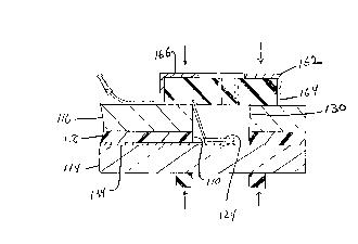
from its edge. More specifically, referring to Figure 9, glass ply 1 16
includes a hole 130 within its periphery which is positioned to overlay
electroconductive extension 134 on glass ply 1 14 of windshield 1 12. A
corresponding hole 1 10 is formed in interlayer 1 18. A connector 124 is
positioned within the hole 130 and secured to the extension 134. A mold
fixture 162 having a resilient mold 164 and backing plate 166, similar to
that discussed earlier may be secured to the windshield 1 12 in any
convenient manner to cover the hole 130. Sealant (not shown) could
then be injected through the mold fixture 162 to seal the hole 130 and
further secure the connector 124 in place.
The invention described and illustrated herein represents a
description of illustrative preferred embodiments thereof. It is understood
that various changes may be made without departing from the gist of the
invention defined by the claims that follow.