Some of the information on this Web page has been provided by external sources. The Government of Canada is not responsible for the accuracy, reliability or currency of the information supplied by external sources. Users wishing to rely upon this information should consult directly with the source of the information. Content provided by external sources is not subject to official languages, privacy and accessibility requirements.
Any discrepancies in the text and image of the Claims and Abstract are due to differing posting times. Text of the Claims and Abstract are posted:
| (12) Patent: | (11) CA 2212607 |
|---|---|
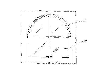
| (54) English Title: | ARCH FRAME |
| (54) French Title: | STRUCTURE D'ARCHE |
| Status: | Expired and beyond the Period of Reversal |
| (51) International Patent Classification (IPC): |
|
|---|---|
| (72) Inventors : |
|
| (73) Owners : |
|
| (71) Applicants : |
|
| (74) Agent: | EUGENE J. A. GIERCZAKGIERCZAK, EUGENE J. A. |
| (74) Associate agent: | |
| (45) Issued: | 2003-04-22 |
| (22) Filed Date: | 1997-08-08 |
| (41) Open to Public Inspection: | 1998-02-22 |
| Examination requested: | 2001-02-21 |
| Availability of licence: | N/A |
| Dedicated to the Public: | N/A |
| (25) Language of filing: | English |
| Patent Cooperation Treaty (PCT): | No |
|---|
| (30) Application Priority Data: | ||||||
|---|---|---|---|---|---|---|
|
A plurality of elongated thermoplastic bar members,
each bar member defining a pre-determined width, and a
pre-determined thickness which is less than its width, and each
bar member being made up of an outer wall, and intermediate
spacer walls and inner walls at intervals, and defining
therebetween generally elongated passageways, and at least
some of the bar members having interlock formations formed
on the exterior of the walls, so that adjacent bar members
may be interlocked together, the interlock formations
permitting one bar member to slide relative to its adjacent
bar members, and at least one of bar members having one wall
free of the interlock formations, so as to provide a smooth
finished exterior surface.
Une multitude d'éléments en forme de barres longitudinales thermoplastiques, chacun définissant une largeur déterminée, et une épaisseur prédéterminée plus petite que la largeur, et chaque élément étant constitué d'une paroi extérieure, d'une paroi intermédiaire et de parois internes à intervalles, qui définissent entre elles des passages généralement longitudinaux et au moins certains des éléments ayant, à l'extérieur des parois, des formes spéciales qui permettent de bloquer ensemble les extrémités d'éléments adjacents, ces formes de blocage permettant à un élément de glisser par rapport aux éléments adjacents de façon à offrir une surface extérieure finie lisse.
Note: Claims are shown in the official language in which they were submitted.
Note: Descriptions are shown in the official language in which they were submitted.
2024-08-01:As part of the Next Generation Patents (NGP) transition, the Canadian Patents Database (CPD) now contains a more detailed Event History, which replicates the Event Log of our new back-office solution.
Please note that "Inactive:" events refers to events no longer in use in our new back-office solution.
For a clearer understanding of the status of the application/patent presented on this page, the site Disclaimer , as well as the definitions for Patent , Event History , Maintenance Fee and Payment History should be consulted.
| Description | Date |
|---|---|
| Time Limit for Reversal Expired | 2010-08-09 |
| Letter Sent | 2009-08-10 |
| Letter Sent | 2006-03-22 |
| Inactive: IPC from MCD | 2006-03-12 |
| Inactive: Agents merged | 2003-05-28 |
| Grant by Issuance | 2003-04-22 |
| Inactive: Cover page published | 2003-04-21 |
| Letter Sent | 2003-02-05 |
| Inactive: Correspondence - Transfer | 2003-01-24 |
| Pre-grant | 2003-01-24 |
| Inactive: Final fee received | 2003-01-24 |
| Notice of Allowance is Issued | 2002-12-02 |
| Letter Sent | 2002-12-02 |
| Notice of Allowance is Issued | 2002-12-02 |
| Inactive: Approved for allowance (AFA) | 2002-11-20 |
| Amendment Received - Voluntary Amendment | 2001-04-18 |
| Request for Examination Requirements Determined Compliant | 2001-02-21 |
| Letter Sent | 2001-02-21 |
| All Requirements for Examination Determined Compliant | 2001-02-21 |
| Request for Examination Received | 2001-02-21 |
| Application Published (Open to Public Inspection) | 1998-02-22 |
| Inactive: IPC assigned | 1997-11-18 |
| Classification Modified | 1997-11-18 |
| Inactive: First IPC assigned | 1997-11-18 |
| Inactive: Correspondence - Formalities | 1997-11-10 |
| Inactive: Applicant deleted | 1997-10-16 |
| Filing Requirements Determined Compliant | 1997-10-16 |
| Inactive: Filing certificate - No RFE (English) | 1997-10-16 |
| Application Received - Regular National | 1997-10-15 |
There is no abandonment history.
The last payment was received on 2002-08-02
Note : If the full payment has not been received on or before the date indicated, a further fee may be required which may be one of the following
Patent fees are adjusted on the 1st of January every year. The amounts above are the current amounts if received by December 31 of the current year.
Please refer to the CIPO
Patent Fees
web page to see all current fee amounts.
| Fee Type | Anniversary Year | Due Date | Paid Date |
|---|---|---|---|
| Registration of a document | 1997-08-08 | ||
| Application fee - standard | 1997-08-08 | ||
| MF (application, 2nd anniv.) - standard | 02 | 1999-08-09 | 1999-07-30 |
| MF (application, 3rd anniv.) - standard | 03 | 2000-08-08 | 2000-07-24 |
| Request for examination - standard | 2001-02-21 | ||
| MF (application, 4th anniv.) - standard | 04 | 2001-08-08 | 2001-07-23 |
| MF (application, 5th anniv.) - standard | 05 | 2002-08-08 | 2002-08-02 |
| Final fee - standard | 2003-01-24 | ||
| MF (patent, 6th anniv.) - standard | 2003-08-08 | 2003-07-16 | |
| MF (patent, 7th anniv.) - standard | 2004-08-09 | 2004-08-05 | |
| MF (patent, 8th anniv.) - standard | 2005-08-08 | 2005-07-29 | |
| Registration of a document | 2006-02-15 | ||
| MF (patent, 9th anniv.) - standard | 2006-08-08 | 2006-07-19 | |
| MF (patent, 10th anniv.) - standard | 2007-08-08 | 2007-07-31 | |
| MF (patent, 11th anniv.) - standard | 2008-08-08 | 2008-08-08 |
Note: Records showing the ownership history in alphabetical order.
| Current Owners on Record |
|---|
| HUNTER DOUGLAS CANADA INC. |
| Past Owners on Record |
|---|
| NORBERT MAROCCO |

