Note: Descriptions are shown in the official language in which they were submitted.
CA 0221267~ 1997-08-08
GROMMET AND ADJUSTABLE
STRAP FASTENER ASSEMBLY
BACKGROUND OF THE ~NVENTION
The im~ention relates generally to fastener asseml~lies. and more
particularly to fastener assemblies including one or more grolllmet and adjustable
straps useable for retaining a tubular core bet~een disl; shaped Ilanges to form a spool
assembl)~ about which coiled materials includillg coiled copper tubing is packaged.
Adjustable strap t~pe fastenillg nlelllbers llave mally useful applications
including the bulldlillg of cables~ conduits and other loads. A well known and
commonl!~ used article for tllis pul~pose is a ullitarS n~lon cable tie havillg an elongate
flexible strap portion and an enlargecl head portioll wit]1 an aperture and a retentioll
melllber protrudillg into tlle aperture. A tip of the e]ongate strap portion is disposable
tllrougll tlle aperture of the head portioll to form a loop and the retention nlell1ber
pemlits one-~ a~ p~ssage of the strap tlleretl~l ough wherein the loop is usually
tiglltelled about a ]oad disposecl ~ithill the loc p. Some al~plications require that the
cable tie b e fastelled to a mc Ulltillg nlelllber alld for thcse applications it is known to
configure the head portioll of tlle cable tie ~illl an apel-ture for recei~ing a moullting
bolt or to configllre Ihe head pOI'tiOll of the cable tie witll a ball~ed memberdisposable ill an apel-tllre of tllc nlolilltil)~ Illcllll-er.
Other apl-licatiolls reclllire tl~c rctelltiol1 of a load bet\lcell separate
nlolll1tillg nlcllll ers but tllis t~ c of rclell~ion is nOt t)~l~ically pcl-folll1cd b~ cable ties.
In tlle copper tubillg industly for e.~all~l~lc it is kno~ll to package pre-coiled copper
t~lbillg about ~ s~ l as~lllbly Ill~cle r,O,., ~ I-I-ug lte(l c ~ board ~ telial ~sselllbled
dul-ing tllc packagillg l~rocess. I\~lolc spccificlllls~ plc-coilcd coppc r tubing is disposed
abo~lt a tubulal COIC lla~ing a bottolll cll-l ra~slcllccl Oll a fil-.st disk sll.al~ecl flange. After
tlle coilcd coppcr tul ing is disposccl abollt tl~c tllbular core a second disk s]laped
flallgc- is fastenccl on all opl~osill~ top ~siclc of lllc lllbulal core. 'I'llc tubulal- core
incllldes a pllllalil~ of fingcls or tal~gs l~lo~ dil~g flo"l its opposillg top ancl l~oltolll
sidcs. D~lling asscn~l 15~ eacll fillgcr on ll~c ~ul-lllal CCIC is disl~osccl t]llOUgll a
30 ~oll-~sl~oll~lill~slo~ rilSl~ cl~cOI~ cll-C(l fl~ gcs. Tl~c ri,-gc,s ~llC tlle
CA 0221267F7 1997-08-08
Dave G. KOTOWSKI et al.
"Grommet and Adjustable
Strap Fastener A~,sembly"
folded over and secured to the disk shaped flanges witl~ staples. The end portions of
the nanges are folded again and disposed in a second corresponding slot in the disk
shaped flanges. The spool assembly process, llowever, is performed manually and is
e~tremely laborious since each tang must be aligned with a corresponding slot and
S inserted theret}lrougll before fastening with staples. The cardboard spools, moreover,
have a tendency to deteriorate during shippillg and llandling, particularly the tangs,
whicll tend to tear along the folds and separate from the staples.
The invelltors of the present invelltioll recogllize that Inally fastening
applications and the assembly and fastenillg of spool assemblies including cardboard
spool assemblies useable for packaging coiled copper tUllillg may be performed more
effectively with a novel grollllllet and adjustal le strap fasteller assembly tllan witl~ prior
art cable ties and fasteners.
It is thelefore an object of tlle illvelltioll tc plovide a novel fasteller
assembly that overc( llles problellls in tlle prior art.
It is also all object of tllc illvelltioll to pl-ovide a novel glo~ et ancl .strap
fastener asselnbl~ tllat is econolllical and l-elatively easy to apply.
It is allotller object of tlle illVCI~tiOI~ to l~l-ovide a novel glollllllet andstl ap fastener asselllbly illcluclillg at least ol~e gl oll~nlet alld all adjustable strap wllereill
the strap is retaillable in a strap apel-tul-e tllrougll tlle grollllllet by a retelltioll melllber
protr-l(lillg into tlle strap aperture.
It is yet allotller object of thc illvclltioll to pl-ovi(le a novel grollllllet and
strap fasteller ass,elllbly includillg a grollllllet tllat is ll~oulltable Oll a l]lo~lntillg nlelllber.
lt is a fultllcr object of tllc illvClltiOIl to provide a novel gromlllet and
strap fasteller asselllbly usable fol retaillil~g a tubulal- corc betwcen OppOSillg flallge
Illclllbers to forlll a spool useable for p~ lgil)g ~oiled nlatcrials illcllldillg ( opl)er
tubil-g.
Tl~e pl-esellt illv(:lltioll i~" a( cor(lillgl~, dl.l~vll to a g~lOllllllCt all(l adj~lstable
CA 0221267~ 1997-08-08
Dave G. KOTOWSKI et al.
"Grommet and Adjustable
Strap Fastener Assembly"
strap fastener assembl)~ comprising a elongate strap melllber which n~ay be rigid or
flexib]e having a head portion at a first end in combination with 2t leasl one separate
body member having a first strap aperture for receiving the elongate strap member.
A retention member protruding into the first strap aperture of tlle body member
permits adjustable passage of the elongate strap member through the first strap
aperture in a first direction. The retention member prevents passage of the e]ongate
strap member through the first strap aperture in a second directioll opposite the first
direction. In an alte. lative configuration the body member includes a second strap
aperture disposed in a recess in the body Inelllker wherein the head portion of the
elon~ate strap melllber is disposal le in the recess whell the elongate strap nlell~ber is
disposed tllrough the second slrap aperture.
According to anotller aspect of the invention the grommet of the
fastener asscnlbly is nloulltable on a moulltillg surface of a moulltillg nlelllber. ln one
applicatio!l one or nlore fasteller assemblies retain a tubular core nlelllber beh~een
first ancl second spool flanges each disposed on OppOSillg sides of the tul lllal- core
nlelllber to form a spool asselllbly usal~le for packagillg coiled nlatelials includillg
copper tubing. In one retentioll configul-atioll the fastcnel- assenlbly of the present
invelltion includes a gromlllet disposed on sides of correspolldillg spool flallges and
at least one elongate strap melllber disposable thrc)ugll an aperture of the first spool
flange througll the intelior of tlle tubulal core melllber and thl-ougll an apeltul-e of
the second spool ilange whel eill tlle clongate strap melllber is fastened to the
OppOSillg grOnlllletS-IIldCI tensioll to retaill lhe t~lbular core mclllbcr bet~vcell the first
~nd second spool flallges.
l hcse and other objccts fcatul-es an(l adv~ntagcs of tlle plcsellt
invcntioll will becolllc nlore fully appcllcnt UpOll col~sidcr~tioll of thc followillg
Dctailcd Descriptioll of thc IllVCntiOIl Witll the accoll~pans~illg dl~willgS~ WhiC]l Illay be
disl)lopor~ionatc for easc Or ul~dclslall(lillg~ w]lCICill likc sll-lcl-lle and slcps ~re
CA 0221267S 1997-08-08
Dave G. KOTOWSKI el al.
"Grommet and Adjustable
Strap Fastener Assembly"
referer.ced by corresponding numerals and indicators.
BRIEF DESCRlPTlON OFr~HE DRAWII\~GS
FIG. la is a partia~ sectional view of a grommet, taken along lines 1- I
of FIG. lb, usable with a grommet and strap fasteller assembly according to an
exemplary embodinlent of the invention.
FIG. lb is a top view of a grommet usable witll a grommet and strap
fastener assembly according to an exemplaly embo(lilIlellt of tlie invelltiorl.
FlG. Ic is an end view of the grommet taken along lines 11 - II of FIG.
Ib.
FIG. 1 d is a bottom view of a grollInlet usable v~!itll a gronIlllet and slrap
fastener assembly according to an exemplar) embo(lilIlellt of the invelItion.
FIG. 2 is a side view of a stlap usable with a gronllIlet and strap
fastener assenIbl~ according to an exelllplaly embodilllelIt of the in~elltion.
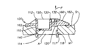
FIG. 3 is a partial sectional view of a grollllllet and adjustable strap
fastencr assel~lbl~ accordilIg to an exenlplaly embo(lilllellt and applicatioll of the
nvelltlon.
~IG. 4a is a partial plan vic~ of a gronllllet and acljustab]e strap fastcner
assembly according to anotller exenlplaly cmbodilllellt an ~ applicatioll of tlle invelltion,
whicll is illustrative of a view takcn along lines 111 - 111 of l-IG. 4b.
FlG. 4b is a partial sectional vicw of gronllllet an(l adjustable strap
fastener assenlbly in combillcltioll with a sl~ool asselllbly usable for packaging coiled
matclials incl~ldillg coilcd coppel tubing.
CA 0221267S 1997-08-08
Dave G. KOTOWSK~ et al.
"Grommet and Adjustab]e
Strap Fastener Assembly"
DETAILED DESCRIPTION OF THE 11~'~NTION
The grommet and adjustable strap fastener assembly of the present
invention comprises generally at ]east one gron~lIlet conlIectable with a strap to form
the fastener assembly, and more generally one or more grommets connectable with
one or more straps to form a fastener assembly. FlGS. Ia - ld illustrate variousrelated ~ie~s of a grommet 100 having several features usable with the fastener
assembly of the present invention, and FIG. 2 illustrates a strap 200 lla~ing several
features usable with tlle fastener assembly of the present invention.
According to one aspect of tlIe invention, the gromlIlet ]00 comprises
a bod~ menIber 1]0 lIaving a first strap aperture ]20 ~ith a retentioll member 130
protruding into the first strap aperture 120? and the strap 200 comprises an elolIgate
strap member 210 with a strap engagelIlellt surface 220. The elongate strap melIlber
210 is disposable in t}le first strap aperture l20 of t}le grommet 100 whelein the
retentioll mell~ber ]30 is engageable ~ith the strap el)gagelIlellt surface 220. The
retentiol1 mellIber 130 pel-lllits adjus~able feecling or passage of the strap 200 through
t}le first strap apeltllre 120 in a first direction F, and the retention nlel~ er 130
prevents passage of tllc strap 200 t}lrougll tlle first strap a~erture 120 in a second
directiolI opposite the first direction F. Tlle clongate strap n~elllber 210 thel-efore may
l~e irre~ersibl~ fed or passecl tllrougll tllc first strap apeltlll-e 120 in the first dircction
to sccure a load as ful-ther discussed below.
III onc elllbodin]elIt, tlle Ictcn(ioll mell~ber 130 is a resilicnt ratcl~eting
nlelllbel l~iased to cOnstl-ict or reduce the first stlap apcrture 120 ~'~'}lClCill thc rCSiliellt
nIclllber is also nexible agaillst its bias to enlarge tlle constlicted filst strap apeltllre
120. Tlle re~siliel~t ratcl~etillg Illember is accol(lillgly biased toward all elongatc(l strap
nlelIll~er 210 disposccl il] t}le first strap al-el(llre 120 ~-~}lereilI t}le rcllc}lctilIg nlelllber
is eng.lgcablc ~ ith tllc stl-ap ellgagelnellt sulf.lcc 22n to plc~!elIt p(-lssage of tllc strap
CA 0221267~ 1997-08-08
Dave G KOTOWSK~ et al
"Grommet and Adjustable
Strap Fastener Assembly"
200 in the second direction tllrough the first strap aperture 120. The resilientratchetiilg member is also flexible away from the strap 200 disposed in the first strap
aperture 120 when tlIe strap 200 is fed in the first direction through the first strap
aperture 120 wherein the resilient ratcheting member is disengagable from the strap
engagement surface 220 to permit passage of the strap 200 in the first direction F
In the exemplary embodiment of the invention the strap engagement
surface 220 includes a pluralit)~ of serrations 222, and the retention member 130
inc]udes one or Inore barbs or teeth 132 biased into engag~ ent with tlle serrations
222 of the strap disposed in the first s~rap aperture 120. The serrations 222 are
enoaged by the l-arbs or teeth 132 to prevent passage or feeding of tlle strap 200 in the
secGnd direction througlI the first strap aperture 120, but the barbs or teeth 132 permit
adjustal-le feedilIg or passage of the strap 200 in the first direction F tlIrough the first
strap aperture 120.
AccordilIg to anotlIer aspec~ of ~l~e il~vention the gromlllet b ody nIelnber
110 con~prises a secon~ strap aperture 140 disposed in a recess 150 in a first end
portion 112 of the body nlelIlber 110 and the strap 200 includes an enlarged head
portion 230 coupled to tl-e elongate strap Inelllber 210. The elongate strap melIlber
210 is disposable tllrougll tlle second strap apelture 140 and the head portion 230 of
the strap 200 is disposable in the reccss 150 of tlIe glolIlmet body nIelllber 110 The
reccss 150 is preferably configllred so that tlle hcad portion 230 of the strap 200 does
not fonIl a discontilIuous protnJsioll frolIl tlIe first side portion 112 of tlle grolllmet
100 The grolIllllct 100 may include eitlIer one or both tlle first strap aperture 120 and
rctcntiolI melIlber 130 and the sccond strap apcl ture 140 dcpending on the
requil-clnents of thc particulal- appliciltioll as disc~lssccl fultller below
Accordillg to anotl)el aspcct of tlle invclltiol)~ thc gron~ et body mclllber
110 conll~rises a flangc poltioll lG0 cxtclI(lillg out~v.ll-(lly fronl the first cnd portioll 112
and l)avillg a surface 162 moulltable on a IllOUlltillg s~llface S of a lno~lllt;llg nlelllber
CA 0221267S 1997-08-08
Da~e G. KOTOWSKI et al.
"Gromrmet and Adjustable
Strap Fastener Assembly"
M. In an a]ternative configuration, howe~e, a second end portion 1]4 of the bodymember 110 is mountab]e on the mounting surface S of the mounting melIlber M in
the absence of the ilange portion. The first side portion 112 of the grommet body
member 110 of the exemplary embodiment includes a bevelled surface to reduce anydiscontinuity resulting from the presence of the grommet 100 mounted on the surface
S of the mounting member M.
According to yet another aspect of the invention, the body member 110
comprises a retaining member for securilIg the grollllllet body nlell1her 1]0 in an
aperture A of the mo-lllting member M. In the exemplary configuration of FlG. la,
the retaining melIIber is one or more resilient legs 116, ShO~'Il in part, extending from
the second side portion 114 of the body member and includilIg an outwardly
protruding flange 117 for engaging the lnounting member M. IlI the exelnplary
embodilIlent of FIGS. 1c and ld, the retainilIg member is one or more longitudinal
ridges or ribs ] 18 protrudillg from outer side po rtions 1 l l of the body melIlber ] 10 for
frictiolIally engagilIo surfaces defining the apert-lre A in the 1110Ulltillg member M,
alllIougll an arralIgelllent of one or more anllular ribs may alterlIatively be disposed
about the outer side portion 111. In ~et another enIbodillIellt~ outer sicle portions 111
of thc body nlelllber 1 ] 0 frictionally engage the sul-faces definilIg thc aperture A of the
grolnlllct body mellIber 110 in the absence of the ribs 11~. The body retainilIgnlellIbel may, more generally, include colnbillatiolls of one or mole of the exenlplary
elnbodillIclIts cliscussed above.
Accoldillg to the exenll71al~ cn~l odillIcllt of I~IG. ], the gronIlnet 100 is
a Ulli~clly mellIber fornled l-referabl~ of a nlol(Jable l-lastie nl<lterial inellldillg nylon.
rhe grollIlnet 100 of the excnlplary embodinlcllt is conrigurcd for Inol(lillg in a lwo-
p.lrt nlold, ~hic}l is particularly cconolllical. In altcrllati~c clnbodillIclIts~ howevel-, the
glolnlllet 100 Inay be formed of other nl(ltel-ials incl-l(ling conlposites alld mctals
folnlecl in olhel- pl-ocesses hlelll(ling a eastillg pr<)cess. rhe glC)IlllllCl ]00 Illay also be
CA 0221267S 1997-08-08
Dave G. KOTOWSKl et a].
"Grommet and Adjustab]e
Strap Fastener Assembly"
an assembly of separate components formed of one or mole different materials. FIG.
Ib shows a plurality of recesses 113, which are readily moldab]e, or cast, or otherwise
formed on the first end portion 112 of the grommet to reduce raw material usage and
reduce weight without loss of structural integrity.
According to the exemplary embodilIlent of FIG. 2, the strap 200 is also
a unitary member formed preferably of a plastic material including nylon. A strap 2()0
having an elongate strap member 210 with a strap engagement surface 220, a head
portion 230, and other features suitable for use with the grommet and adjustab]e strap
fastener assembly of the present invention is a cable tie of the type commercially
available from Panduit, Chicago, lI]inois. FlG. 2 illustrates a cable tie including a
cable strap aperture 240 having a retention melIlber 250 protr-lding into the aperlure
240, wllich operates to retain the strap in substantially the same mallller as the
retention member 130 of the grolnmet 1n0 discussed above. Tlle strap 200 a]so
illcludes genel-ally an end portion 260 with a tapered tip 262 to facilitate insertion of
the elongate strap member 210 into a strap aperture.
According to the exemplaly app]ication and embodilllel~t of tl~e gromlllet
and adjustable strap fastener assenlbly of I~IG. 3, a portioll of a grolnlllet 200 is
disposed in an aperture A and supl-orted on a n~oulltillg surface S of a mo~lllting
mell~ber M as discussed above. ~n clol~gatc strap nlclllber 210 of a strap 200 is
disposecl through the second strap aperture 140 of the grollllllet 100 alld the head
portion 230 of ttle strap 200 is disposed illthe strap recess 150 of thc groll~lnet 100.
The elongate strap member 210 is loopcd about a loacl I, and all end pOItiOIl of the
elongate strap melllber 210 is adjustably disposed and retaillcd ill tl)e first strap
apertuI-e 120 by the retention nIclllber ]30 as discussed above to retaill tlle load L.
In an alterl)ative app]icatioll alIcl embo(lilllelIt of the gromllIet and
adjustable strap faslener asscnIbly of the il~vel~tiOIl, wlliCIl iS a valia~iolI ~11 tlle
c~;elIlpl(~ elnbodilllellt of l~lG. 3, ri~st alld SCCOlld Sepalate glOllllllets 100 are
CA 0221267~ 1997-08-08
Dave G KOTOWSKI ~t al
"Grommet and Adjustable
Strap Fastener Assembly"
disposed in corresponding separate apertures A and supportcd on a mc,unting surface
S of a common moulltillg member M, and a con~lllon strap 200 is coupled to the first
and second grommets to forrn the fastener assembly According to this a]ternativeapplication and embodiment, the elongate strap member 210 of the strap 200 is
disposed through the second strap aperture 140 of the hrst grommet 100 and the head
portion 230 of tlle strap 200 is disposed in the strap recess ]50 of the first grommet
100, and the end portion of the elongate strap melllber 2]0 is adjustably disposed
through and retained in the first strap aperture ]20 of the first grcmmet 100 asdiscussed aboYe to retain the load L
In yet anotller alternative app]ication and embodimellt of the grommet
and adjustable strap fastener assembly of the invelltion, ~!hich is also a variation on the
exemplary embodinlent of FIG.3~tI1e CIOI1gate StIaPI11eI11ber 210 of the strap 200 is
disposed througll a strap aperture, not sllo~n, in the mo~lnting melllber M wllereill the
head portion 230 Of the strap is supported directly On the mountillg surface S of the
moulltillg mellll~er M without a gronllllet Some applicatiolls may req~lire that the
strap have an enlarged head portion 230 jnC1UdjI1g possibly a bevelled surface to
maintaill a degree of COlltillUity Witllt]lelnC)UlllillgsUlfaCC S Oft]1e nlo-llltillg melllber
M A portion of the elongate strap mellll~er 210jS adjustably disposed tl~rough and
retained in tlle first strap aperture I20 Of a grc nllllet 100 disposed in allotl]er apertllre
of tlle moulltillg nlcllll~er M as discussed alove to support tlle load L
Accordillg to the exeml~lary applicatioll and enlbodilllcnt of tlle gron]met
and adjustable slrap fastener assembly Of~1G. 4a, first alld sccond sepal-ate gromll~ets
100, 100' are disposed in correspondillg apcl-t~lres A, A' and sul~portcd on
correspolldillg nlo-llltillg surfaces S, S' of ~orlcspolldillg moulltillg melllbcrs M, M'
separated by a load 1, wllich is retaillcd bch~celltI1C nlolllltillg mcnll ers M, M' An
elongatc strap nlelllber 210 of tlle strap 200 jS c]isposecl tllrougll tlle secolld s~rap
al~crtul-c 140 Oftlle f;ISt grOmII1et I00 aI1(ItI1C I1Cad ]~OltiOIl 230 OftI1C stl-ap 200 is
CA 0221267S 1997-08-08
Dave G. KOTOWSKl et al.
- "Grommet and Adjustab]e
Strap Fastener Assembly"
disposed in the strap recess 150 of the first grommet 100. The end portion of tlle
same elongate strap member 210 is adjustably disposed through and retained in the
first strap aperture 120 of the second grommet 100' as discussed above to retain the
load L betueen the first and second mounting members M, M'. In an altemative
conhguration, a second strap, not shown, is disposed between the first and second
grommets 100, 100' substantially parallel to the first strap for additional retention
strength. More generally, a plurality of fastener assemblies including two grommets
100 and at least one strap 200 are useable to retain the load L between the mounting
members M, M'. In an alternative application and fas~ener assembly configuration, the
head portion 230 of the strap 200 is supported directly on tlle mounting surface S of
one of the mounting members M in the absence of a grommet.
FIG. 4b is plan view of a spool assembly 500 of the type usable for
packaging coiled articles including coiled copper tubing. The spool 500 includes a
tubular core member 5]0 and first and second spool flanges 520 eaclI disposed and
retained on OppOSillg sides of the tubular core melllber 510 by one or more gronlmet
and adjustable strap fastener assemblies of the presellt invelltion. FIG. 4a is
illustrative of a partial sectional view taken alollg lines 111 - III of FIG. 4b whereilI the
flallges 520 correspolId to the mounting n~embers M, M', and the tubular core 510
corresponds to tlle load L. The gronIlllets are disposed over, and may be partially
disposed in, correspolldillg apertllres 522 in the spool flanges 520 whel-eill the aperture
in eacll flallge is aligned witlI a correspondilIg apertul-e in tlle opposing spool flange
520. FIG. 4b sl)ows the apertures located interiol- of the tubular core nlellIber 510 to
prevent interference with the coiled nIatelial on ~he tublllal- core 510. One or nIore
straps 200 intercollllecting tlle OppOSilIg pail-s of grollllllets rctain tlle tubulal- core
bctween flanges 510. More genel-ally, a plurality of grolIlmet and strap fastcller
a~s~scnlblies are arrallged, prefcrably synllllctlically, about tlIC spool 500 to sccurely
letaill llle tubular core 510 l ct~vecn tl~e spool nangcs 520. In one cn]l-o(lilIlcllt, the
CA 0221267~ 1997-08-08
Dave G. KOTOWSKI et al.
"Grommet and Adjustable
Strap Fastener Assembly"
spool flanges 520 each include a circular score on one side thereof for concentrically
aligning and positioning the flanges relative to the tubu]ar core 510 before application
of the fastener assembly or assemblies.
In some applications, depending on strap 200 configuralion, tl-e grommet
100 is configured so that the retention member I30 protrudes into an opposing side
of the first aperture ~20, relative to the side sllowll in exemplary embodiments, or
alternatively so that the second strap aperture 140 is ]ocated on an opposing side of
the recess 150, to properly align or orient the engagement surface 220 of the elongate
strap member 2]0 for engagement by the retention member 130.
~hile the foregoing written description of the invention enables anyone
skil]ed in the art to make and use what is at present considered to be the best mode
of the invention, it will be appreciated and understood by those skilled in the art the
existence of variations, combinations, modifications and equivalents within the spirit
and scope of the specific exemplary embodilllellts disclosed herein. The prcsentinvelltioll therefore is to be limited not by the specific cxemplary embodimentsdisclosed hereill but by all embodimellts withill the scope of the appended claims.