Note: Descriptions are shown in the official language in which they were submitted.
CA 02212678 1997-08-11
FIBI~R-REINFORC~D RODLIKE ARTICLE
FIELD OF THE INVENTION
The present invention relates generally to a rodlike article, and
more particularly to the rodlike article which is reinforced by fiber.
BACKGROUND OF TlIE INVENTION
The sports equipments, such as game racket, golf club, billiard cue,
hockey stick, ski stick, fishing rod, and even bicycle frame, are generally
made of a rodlike or tubular article of a thermoplastic or thermosetting
plastic material. The rodlike or tubular article is generally reinforced by
fiber braids, which are arranged spirally such that the fiber braids and the
axis of the article form an angle so as to make the rodlike or tubular
article more resistant to flexure and torsion. However, the rodlike or
tubular artlcle is often locally reinforced by a fiber-reinforced plastic
composite material such that a specific area of the rodlike or tubular
article has a greater resistance to flexure.
The process of reinforcing a specific area of the rodlike article is
CA 02212678 1997-08-11
rather cumbersome and is not cost-effective. In addition, the local
reinforcement of a rodlike article often results in an increase in the
thickness and the weight of the rodlike article. Moreover, the interlacing
fiber braids used for the reinforcement can undermine the external
esthetic effect of the rodlik~-article. The rodlike article, which is
reinforced by the fiber braids, is also vulnerable to severance caused by
the concentration of stress. In order to remedy this drawback, the
portions, where the stress concentration is prone to take place, must be
reinforced with a fiber fabric. The addition of the fiber fabric will
undoubtedly result in an increase in the cost of making the rodlike article.
SUMMARY OF THE INVENTION
It is therefore the primary objective of the present invention to
provide a rodlike article reinforced by the fiber braids capable of
averting the stress concentration at the reinforced area of the rodlike
article.
It is another objective of the present invention to provide a rodlike
article reinforced by the fiber braids which are so arranged as to enhance
the resistance of the rodlike article to flexure and torsion.
It is still another objective of the present invention to provide a
rodlike article reinforced by the fiber braids which are so arranged as to
enhance the external esthetic effect of the rodlike article.
In keeping with the principle of the present invention, the
CA 02212678 1997-08-11
foregoing objectives of the present invention are attained by a fiber-
reinforced article of a rodlike construction. The article consists of a
tubular body and a plurality of fiber braids. Each of the fiber braids has
at least one first section parallel to the axis of the tubular body, and at
least one second section forming an angle with the axis of the tubular
body. The tubular body is so reinforced by the fiber braids as to be
resistant to flexure and torsion, without compromising the esthetic effect
of the rodlike article.
The foregoing objectives, features and fi~nctions of the present
invention will be more readily understood upon a thoughtfiul deliberation
of the following detailed description of the embodiments of the present
invention with reference to the accompanying drawings.
BRIEI~ DESCRIPTION Ol~ THE DRAWINGS
FIG. l-A shows a front view of a first preferred embodiment of the
present invention.
FIG. 1-B shows a partial enlarged view of the second section of
the fiber braids of the first preferred embodiment of the present
invenhon.
FIG. 2 shows a sectional view taken along the direction indicated
by a line 2-2 as shown in FIG. 1-A.
FIG. 3 shows a sectional view taken along the direction indicated
CA 02212678 1997-08-11
by a line 3-3 as shown in FIG. l-A.
FIG. 4 shows a sectional view of a second preferred embodiment
of the present invention, with the sectional view being taken along the
direction similar to that of FIG.~.
FIG. S shows a front view of a third preferred embodiment of the
present invention.
FIG. 6 shows a sectional view of a portion taken along the
direction indicated by a line 6-6 as shown in FIG. 5.
FIG. 7-A shows a front view of a fourth preferred embodiment of
the present invention.
FIG. 7-B shows a partial enlarged view of the second section of
the fiber braids of the fourth preferred embodiment of the present
mvention.
FIG. 8 shows a front view of a fifth preferred embodiment of the
present invention.
FIG. 9 shows a front view of a sixth preferred embodiment of the
present invention.
FIG. 10 shows a front view of a seventh preferred embodiment of
the present invention.
FIG. 11 shows a front view of an eighth preferred embodiment of
the present invention.
CA 02212678 1997-08-11
DETAILED DESCRIPTION OF THE ~NVENTION
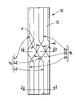
As shown in FIGS. 1-3, a rodlike article 10 embodied in the
present inventlon is composed of a body 12 and a plurality of first fiber
braids 14 and second fiber braids 16.
The body 12 of a tubular construction is made of a thermoplastic
or therrnosetting plastic material and is provided with an axial hole 20.
The body 12 has a length and a thickness. The body 12 may be solid.
The first fiber braids 14 are made of carbon fiber, boron fiber,
glass fiber, titanium fiber, the "DYNEEMA" fiber made by DSM
Corporation of the Netherlands, or the "KEVL~R" fiber made by the
DuPont Corporation of the United States. Such fibers as mentioned
above are strong and tough. The first fiber braids 14 are wound around
the external surface of the body 12 such that they are separated from one
another at an interval, and that they are respectively divided into a first
section 41 corresponding to one end of the body 12, a second section 42
corresponding to the midsegment of the body 12, and a third section 43
corresponding to another end of the body 12. The first section 41 and the
third section 43 are parallel to the axis of the body 12 while the second
section 42 forms a first predetermined angle (+ a ) with the axis of the
body 12. Both ends of the body 12 are respectively connected with the
first section 41 and the third section 43.
The second fiber braids 16 are similar to the first fiber braids 14 in
CA 02212678 1997-08-11
that they are made of the same material, and that they are arranged in the
same manner. The second fiber braids 16 are respectively divided into a
fourth section 64 corresponding to one end of the body 12, a fifth section
65 corresponding to the midsegment of the body 12, and a sixth section
66 corresponding to another elld of the body 12. The fourth section 64
and the sixth section 66 are parallel to the axis of the body 12 while the
fifth section 65 forms a second predetermined angle (- a ) with the axis
of the body 12. In view of the fact that the first predetermined angle (+ a )
is opposite to the second predetermined angle (- a ), the second sections
42 and the fifth sections 65 form a network by superimposing one
another, as illustrated in FIG. l-B and FIG. 3.
The tubular body 12 is reinforced by the first fiber braids 14 and
the second fiber braids l6, whose sections are extended continuously so
as to reduce the chance of the stress concentration. In addition, the
network formed by the second sections 42 and the fifth sections 65
serves to enhance the esthetic effect of the tubular body 12. Since the-
second sections 42 and the fifth sections 65 are corresponding in
location to the midsegment of the tubular body 12, the resistance of the
midsegment of the tubular body 12 to flexure and torsion is greatly
enhanced, thanks to the network formed by the second sections 42 and
the fifth sections 65.
Now referring to FIG. 4, the rodlike article 10 of the present
invention is provided on the outer surface thereof with a covering 18
attached thereto for protecting the first fiber braids 14 and the second
fiber braids 16 at the time when the rodlike article 10 is polished
mechanically. The covering 18 may be of a transparent coating material,
such as a glass fiber cloth.
CA 02212678 1997-08-11
As shown in FIGS. 5 and 6, the tubular body 12 is provided with
two first fiber braid groups 15 and two second fiber braid groups 17,
which are arranged alternately on the outer surface of the tubular body
12. Each of the two first fiber braid groups 15 is made up of three first
fiber braids 14 while each of the two second fiber braid groups 17 is
made up of three second fiber braids 16. The first fiber braid groups 15
and the second fiber braid groups 17 are corresponding in location to the
midsegment of the tubular body 12 such that they form four network
areas, which serve to enhance the esthetic effect of the tubular body 12
and the resistance of the midsegment of the tubular body 12 to flexure
and torsion.
As illustrated in FIG. 7, the rodlike article 10 of the fourth
preferred embodiment of the present invention is characterized in design
in that the first fiber braids 14 are provided respectively with a seventh
section 47 forming a first predetermined angle (+ ,l~ ) with the axis of the
tubular body 12, and that the second fiber braids 16 are provided
respectively with an eighth section 68 forming a second predetermined
angle (~ ) with the axis of the tubular body 12, and further that the
seventh sections 47 and the eighth sections 68 form a network. Since the
angles formed by the second sections 42 and the fifth sections 65 are
different in degree from the ,~ angles formed by the seventh sections
47 and the eighth sections 68, the network areas so formed are thus
different from each other in resistance to flexure and torsion. In addition,
the network of the tubular body 12 of the fourth preferred embodiment
of the present invention is formed of the first fiber braids 14 and the
second fiber braids 16 by weaving instead of superimposing.
CA 02212678 1997-08-11
As shown in FIG. 8, the first section 41 of the first fiber braids 14
and the fourth section 64 of the second fiber braids 16 are parallel to the
axis of the tubular body 12. However, the third section 43 of the first
fiber braids 14 and the sixth se~on 66 of the second fiber braids 16 are
not aligned with the first section 41 and the fourth section 64.
As shown in FIGS. 9, 10 and 1 1, the first section 41 and the fourth
section 64 or the second section 42 and the fifth section 65 may be
varied in locality and quantity, depending on the specifications of the
rodlike article 10 of the present invention. By comparing FIG. 9 with
FIG. 7, it can be noted that the rodlike articles 10 of the sixth preferred
embodiment and the fourth preferred embodiment are reinforced
similarly in the structural strength. However, they are enhanced
differently in the esthetic effect. As illustrated in FIG. 10, the present
invention is also applicable to a tapered tube or rod. ~n addition, the
present invention is applicable to a rodlike article 10 having a tapered
body with an enlarged portion 19 which is formed by the networks of the
first fiber braids 14 and the second fiber braids 16 for the purpose of
absorbing shock.