Note: Descriptions are shown in the official language in which they were submitted.
CA 02213026 1999-09-23
- 1 -
SPACER FRAME FOR AN INSULATING UNIT
HAVING STRENGTHENED SIDEWALLS TO RESIST TORSIONAL TWIST
This invention relates to a.spacer stock and/or spacer
frame and to a multi-sheet glazing unit made using the spacer
frame, and, in particular to a spacer frame having strengthened
sidewalls to resist torsional twist.
PRESENTLY AVAILABLE TECHNOLOGY AND TECHNICAL PROBLEMS
European Patent Application Publication Number
0 475 213 A1 published 18.03.92 Bulletin 92/12 (hereinafter
~~EP Application°) based on U.S. Patent Applications Serial
Nos. 578, 697 (now Patent 5,177,916); and 686,956 (now
Patent 5,675,944), respectively
(hereinafter the "EP'Application") and U.S. Patent No.
5,531,047 discloses a thermal insulating glazing unit having an
edge assembly having low thermal conductivity and a method of
making same. In general, the EP Application discloses a
thermal insulating glazing unit having a pair of glass sheets
about and sealed to an edge assembly to provide a sealed
compartment between the sheets, and U.S. Patent No. 5,531,047
further discloses a glass sheet within the spacer frame of the
edge assembly between the sheets. The edge assembly includes a
spacer frame having a generally U-shaped cross section having a
sealant on each of the outer surfaces of the upright legs, and
optionally on the outer surface of the base of the spacer frame
and an adhesive bead having desiccant therein adhered to inner
surface of the base of the spacer frame.
U.S. Patent No. 5,313,761 discloses a spacer frame for
an insulating unit having a generally U-shaped cross section
CA 02213026 1999-09-23
- 2 -
with portions of the upright legs of the spacer frame bent
toward one another over the base of the spacer frame.
Although the design of the spacer frames disclosed in
the EP Application and U.S. Patent Nos. 5,313,761 and 5,531,047
is acceptable, it has limitations.. More particularly, the
sides of the spacer frame between the corners have incremental
torsional twist because the outer legs of the spacer frame are
only interconnected by the base. As can be appreciated, as the
length of the sides between the corners of the spacer frame
l0 increases the degree of twist of the side of the spacer frame
between adjacent corners increases.
U.S. Patent Application Serial No. 08/529,180 (now
Patent 5,617,699), in the name of Albert E. Thompson, Jr.
discloses a spacer stock and/or spacer frame for use in the
manufacture of insulating units that include a generally U-
shape cross section and a base having a "T" shaped
strengthening member to reduce the degree of rotational twist
of the sides of the spacer frame. The strengthening member may
be an insert mounted on the base between the upright legs or a
strengthening member integral with the spacer stock and/or
spacer frame.
Although the use of the insert and/or strengthening
member disclosed in U.S. Patent 5,617,699 reduces
torsional twist, it has limitations. More
particularly, a strengthening member formed integral with the
base of the spacer frame requires cutting out portions of the
base when the spacer frame is formed from a continuous piece of
spacer stock; further, inserts to resist torsional twist
require the additional step of mounting the insert in the
spacer stock or spacer frame and the carrying an inventory of
inserts.
CA 02213026 1999-09-23
- 3 -
As can be appreciated by those skilled in the art of
making multi-sheet glazing units, it would be advantageous to
provide a spacer frame design that does not have the limitation
of the presently available spacer frames to minimize if not
eliminate torsional twist of the sides of the spacer frame.
This invention relates to spacer stock and/or spacer
frame having a base interconnecting a pair of spaced upright
legs to provide the spacer stock and/or spacer frame with a
generally U-shaped cross section. Each of the uprights legs is
formed to minimize if not eliminate torsional twist. In one
embodiment of the invention, the upright legs in cross section
have a first member and a second member connected to have a
hairpin configuration with the first member connected to the
base of the spacer frame and the second member having a radius
end spaced from the base.
Further, the invention relates to a glazing unit
having a pair of sheets spaced from each other by the spacer
frame of the instant invention and secured e.g. by a sealant to
outer surface of the first member of the legs of the spacer
f rame .
Still further, the invention relates to a method of
making the spacer stock and/or spacer frame of the instant
invention and/or of making a multiple glazed unit using the
spacer stock and/or spacer frame of the instant invention.
CA 02213026 1999-09-23
- 3a -
More particularly, in accordance with a further
aspect of the invention there is provided, an elongated
spacer stock used in the manufacture of a spacer frame to
separate sheets of an insulating unit, the spacer stock
comprising:
an elongated base;
a first elongated leg having a first member and a second
member joined together to have a generally U-shaped cross
section;
a second elongated leg having a first member and a
second member joined together to have a generally U-shaped
cross section; wherein
the first and second legs are spaced from and out of
contact with one another and joined to the base to provide a
generally U-shaped cross section with open end of the U
formed by the first and second legs and base in a first
direction, the U-shape of the first leg open in a second
direction, and the U-shape of second leg open in the second
direction with the first and second directions opposite to
one another, and the first and second legs spaced from and
out of contact with one another.
In accordance with a second aspect of the invention
there is provided, an elongated spacer stock used in the
manufacture of a spacer frame to separate sheets of an
insulating unit, the spacer stock comprising:
a base;
a~first leg connected to the base; and
a second leg connected to the base and spaced from the
first leg, wherein the legs and the base are connected to
provide a generally U-shaped cross-section, wherein the
first and second legs have a thickness greater than the
thickness of the base to reduce torsional twist of the
spacer stock.
In accordance with a third aspect of the invention
there is provided, a spacer frame for separating sheets of
an insulating unit, the spacer frame comprising:
a base;
CA 02213026 1999-09-23
- 3b -
a first leg connected to the base, the first leg having
a first member and a second member joined together to have a
generally U-shaped cross section;
a second leg connected to the base, the second leg
having a first member and a second member joined together to
have a generally U-shaped cross section; wherein
the first and second legs are spaced from and out of
contact with one another and connected to the base to
provide the spacer frame with a generally U-shaped cross
section with open end facing in a first direction and
opening of U of the first and second legs facing in a second
direction opposite to the first direction to reduce
torsional twist.
In accordance with a fourth aspect of the invention
there is provided, an insulating unit comprising:
a pair of sheets;
a spacer frame between the pair of sheets, and the
spacer frame comprising:
a base;
a first leg;
a second leg; wherein
the first and second legs are spaced from and out of
contact with one another and joined to the base to provide
the spacer frame in cross section with a generally U-shaped
cross section with the open end of the U facing a first
direction and the first and second legs each including a
first U-shaped member having two ends, one end attached to
the base and the remaining end joined by a radiused portion
to the second member such that the members form a generally
U-shaped cross-sectional configuration with the opening of
the U facing a second direction opposite to the first
direction to reduce torsional twist; and
means for securing the sheets to the spacer frame.
In accordance with a fifth aspect of the invention
there is provided, a method of making and using a spacer
stock comprising the steps of:
providing a strip of bendable material; and
CA 02213026 1999-09-23
- 3c -
shaping the strip to provide an elongated piece of
spacer stock having a base, a first leg and a second leg,
the base and legs joined to provide the spacer stock with a
generally U-shaped cross section with the U open in a first
direction and the first and second legs spaced from one
another and out of contact with one another, and the legs
each having a first member joined to a second member to have
a U-shaped cross section with the opening of the U in a
second direction opposite to the first direction to reduce
torsional twist of the spacer stock.
Embodiments of the invention will now be described
with reference to the accompanying drawings.
BRIEF DESCRIPTION OF THE DRAWINGS
Fig. 1 is front elevated view of a multi-sheet
glazing unit incorporating features of the invention having
portions removed for purposes of clarity.
CA 02213026 1997-08-26 -
- 4 -
Fig. 2 is the view taken along lines 2-2 of Fig. 1
illustrating an embodiment of a spacer frame of the invention
to resist torsional twist.
Fig. 3 is a view similar to the view of Fig. 2 having
outer layer of sealant on the base of the spacer frame removed
showing another embodiment of the spacer frame of the invention
to resist torsional twist.
Fig. 4 is a view similar to the view of Fig. 3 having
outer sheets and layers of sealant removed and an intermediate
sheet within the spacer frame showing still another embodiment
of the spacer frame of the invention to resist torsional twist.
Fig. 5 is a view similar to the view of Fig. 4 having
the intermediate sheet and adhesive containing desiccant
removed showing a further embodiment of the spacer frame of the
invention to resist torsional twist.
Fig. 6 is a view similar to the view of Fig. 5 showing
still a further embodiment of the spacer frame of the invention
to resist torsional twist.
Fig. 7 is a view similar to the view of Fig. 5 showing
another embodiment of the spacer frame of the invention to
resist torsional twist.
Fig. 8 is a side view of a section of spacer stock
having features of the invention to resist torsional twist
formed from the shaped strip shown in Fig. 9.
Fig. 9 is a plan view of a strip after punching and
prior to forming into the section of the spacer stock shown in
Fig. 8.
Fig. 10 is a plan view of a strip after punching and
prior to forming into the spacer stock shown in Fig. 11.
Fig. 11 is a side view of a spacer stock formed from
the strip of Fig. 10 prior to bending to provide a spacer frame
CA 02213026 1999-09-23
- 5 -
having continuous corners and having features of the invention
to resist torsional twist.
Fig. 12 is a view similar to the view shown in Fig. 11
having a continuous base and features of the invention to
resist torsional twist.
DESCRIPTION OF THE PREFERRED EMBODIMENTS
The various embodiments of the spacer stock and/or
spacer frame of the instant invention will be discussed in the
construction of a glazing unit having a low thermal conducting
edge determined using the technique disclosed in the EP
Application or in U.S. Patent No. 5,351,451.
As will be appreciated,
the instant invention is not limited to a multi-sheet glazing
unit that is thermally insulating and/or has a low thermal
conductive edge, and that the embodiments of the present
invention may be used with a multi-sheet glazing unit
regardless of its thermal insulating properties, if any. In
the following discussion unless otherwise indicated like
numerals refer to like elements.
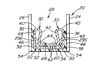
Fig. 1 illustrates an insulating unit 20, and Fig. 2
illustrates a cross-sectional view of the insulating unit 20
having spacer frame 22 incorporating features of the invention.
With specific reference to Fig. 2, the unit 20 includes the
spacer frame 22 between and secured to a pair of outer sheets
24 and 26 to provide a compartment 28 therebetween. Preferably
but not limiting to the invention, the compartment 28 is sealed
against the egress and ingress of gas e.g. air, moisture and/or
dust (hereinafter individually and collectively referred to as
~~environmental air~~), and/or the egress of an insulating gas
e.g. argon, in a manner discussed below.
CA 02213026 1999-09-23
- 6 -
In the following discussion, the sheets 24 and 26 are
glass sheets; however, as will become apparent, the sheets may
be made of any material e.g. glass, plastic, metal and/or wood,
and the selection of the materials is not limiting to the
invention. Further, the sheets may be all of the same material
or the sheets may be of different materials, and still further,
one sheet may be a monolithic sheet and the other sheet may be
a laminated sheet e.g. made of one or more monolithic sheets
laminated together in any usual manner. Still further, one or
more of the surfaces of one or more of the sheets may be coated
e.g. glass or plastic transparent sheets may have an opaque
coating of the type used in making spandrels or, an
environmental coating to selectively pass predetermined
wavelength ranges of light. U.S. Patent Nos. 4,610,711;
4,806,220; 4,853,256; 4,170,460; 4,239,816 and 4,719,127.
disclose coated sheets that may be
used in the practice of the invention; however, as can be
appreciated, the instant invention is not limited thereto.
Further, in the practice of the invention, but not limiting
thereto, one or more of the glass sheets may be coated and/or
uncoated colored sheets for example, but not limiting to the
invention, colored sheets of the type disclosed in U.S. Patent
Nos. 4,873,206; 4,.792,536; 5,030,593 and 5,240,886.
The outer sheets 24 and 26 preferably have the same
peripheral configuration and dimensions; however, as can be
appreciated,~one outer sheet may be larger than the other outer
sheet, and one of the sheets may have different peripheral
configuration than the other sheet.
With continued reference to Fig. 2,.the spacer frame
22 includes a pair of spaced outer legs 30 and 32 secured to a
base 34 to provide the spacer frame with a generally U-shaped
. ' CA 02213026 1997-08-26
cross section. Each of the outer legs in cross section as
shown in Fig. 2 have a hairpin configuration and include
elongated upwardly extending or first member 36 having its
bottom portion 38 connected to the base 34 of the spacer frame
22, and upper portion connected at juncture 40 to an elongated
downwardly extending or second member 42. The second member 42
has an end portion 44 bent over the base 34 and facing the end
portion 44 of the second member 42 of the outer leg 32. In the
practice of the invention, it is preferred that the outer legs
30 and 32 be formed from one piece; however, it can be
appreciated that the outer legs 30 and 32 may be made from
separate pieces joined together to provide the cross sectional
shape shown in Fig. 2 for the elongated outer legs 30 and 32.
With continued reference to Fig. 2, a layer 46 of a
moisture impervious sealant e.g. an adhesive-sealant material
of the type used in the art of making multi-sheet glazing units
having sealed compartments is provided on outer surface 48 of
the outer legs 30 and 32 of the spacer frame 22 to secure the
outer sheets 24 and 26 e.g. marginal edge portions of the
sheets to outer surface 48 of the outer legs 30 and 32
respectively of the spacer frame 22 to seal the compartment 28
against movement of environmental air into and out of the
compartment 28.
Not limiting to the invention, a layer 50 of a sealant
or adhesive-sealant may be provided over outer surface 52 of
the base 34 of the spacer frame 22. The layer 50 may be
material similar to the material of the layers 46; however, it
is preferred that the material of the layer 50 be non-tacky so
that the units 20 when stored or shipped on an edge do not
stick to the supporting surface. Further, the units having the
layer 50, have the spacer frame 22 preferably spaced from
peripheral edges 54 of the outer sheets 24 and 26 to provide a
', CA 02213026 1997-08-26
_ g _
channel filled with the layer 50 as shown in Fig. 2. As can
now be appreciated by those skilled in the art of making multi-
sheet glazing units; the channel having the layer 50 may be
' eliminated for example, by setting the outer surface 52 of the
base 34 of the spacer frame 22 level with the peripheral edges
54 of the sheets 24 and 26 as shown in Fig. 3 or beyond the
peripheral edges 54 of the sheets 24 and 26.
As can be appreciated by those skilled in the art, the
compartment 28 is usually filled with an insulating gas e.g.
Argon, and it is, therefore, recommended that the sealant layer
46 be thin (the thickness of the layer 46 is measured between
adjacent major surface of the sheet and the adjacent outer
surface of the first member 36) and long (the length of the
layer 46 is measured from the peripheral edge 54 of the outer
sheets 24 and 26 upward as viewed in Fig. 2 toward the
compartment 28) to reduce the diffusion of the insulating gas
out of the compartment 28 of the unit 20 or the environmental
air moving into the compartment 28 of the unit 20. The
material for the layer 46 preferably has a moisture
permeability of less than 20 gm mm/MZ day, and more preferably
less than 5 gm mm/M2 day, determined using the procedure of
ASTM F 372-73. The invention may be practiced with the sealant
layer 46 after pressing the sheets against the legs having a
thickness of about 0.005 inch (0.013 centimeter (hereinafter
"cm")) to about 0.125 inch (0.32 cm), preferably about 0.010
inch (0.025 cm) to about 0.030 inch (0.076 cm) and more
preferably about 0.020 inch (0.51 cm). The layer 46 after
pressing the sheets against the legs has a length or height as
viewed in Fig. 2 of about 0.010 inch (0.025 cm) to about 0.50
inch (1.27 cm), preferably about 0.125 inch (0.32 cm) to about
0.50 inch (1.27 cm) and more preferably about 0.200 inch
(0.50 cm). As can now be appreciated and not limiting to the
CA 02213026 1999-09-23
- 9 -
invention, it is preferred that the height of the layer 46 does
not exceed the height of the outer legs 30 and 32.
Sealants that may be used in the practice of the
invention include but are not limited to butyls, silicones,
polyurethane adhesives, room temperature vulcanizable adhesives
and preferably butyls and butyl hot melts such as H. B. Fuller
1191, H. B. Fuller 1081A and PPG Industries, Inc. 4442 butyl
sealant.
With continued reference to Fig. 2, bead 60 of a
pervious material having a desiccant 62 is provided on portions
of inner surface 64 of the base 34 of the spacer frame 22. The
bead 60 having the desiccant 62 may be of any material known in
the art of manufacturing or designing multi-sheet insulating
glazing units to absorb moisture in the compartment 28, e.g.
moisture captured in the compartment after the outer sheets are
secured to the spacer frame. Using a flowable material
provides for ease of automating the positioning of the bead 60
on the base and/or fabrication of the units. Materials that
may be used in the practice of the invention for the beads are
materials of the type taught in the EP Application and in U.S.
Patent Nos. 5,351,451 and 5,531,047. As can
be appreciated, the bead 60 may be
continuous or in spaced segments along the inner surface 64 of
the spacer frame or on any selected surfaces of the legs 30 and
32 of the spacer frame. Further, as can be appreciated, the
amount of desiccant 62 in the bead 60 is not limiting to the
invention; however, sufficient desiccant should be present to
absorb the moisture in the compartment 28 but not reduce the
adherence of the bead to the spacer frame. In the practice of
the invention normally 40-60% of the total weight of the
desiccant and matrix material is desiccant.
CA 02213026 1997-08-26
r
- 10 -
The spacer frame of the instant invention may be made
of any material and configuration provided the spacer frame has
resistance to torsional twist. Preferably, but not limiting to
the invention, the spacer frame has structural stability to
maintain the outer glass sheets 24 and 26 in spaced
relationship to one another when biasing forces are applied to
secure the unit:20 in a sash or a curtainwall system. Although
the spacer frame of the instant invention may be made of any w
material e.g. wood, plastic, cardboard, compressed paper,-metal
l0. e.g. stainless steel or aluminum, coated metals e.g. galvanized
iron or :ti:n ~oated.steel, it is preferred in the practice of
the invention that the spacer frame be made of metal and most
preferably a low thermal conducting metal e.g. stainless steel,
galvanized iron or tin coated steel such that the spacer frame
has low thermal conductivity. More particularly in the
practice of the invention the edge assembly of the unit which
includes the spacer frame 22, the layers 46, the layer 50 (when
present) and the bead 60 having the desiccant 62 (when present)
has a low thermal conductivity or high RES-value determined as
disclosed in U.S. Patent No. 5,531,047.
Further, as can be appreciated, the spacer frame 22 is
preferably made of- a material that is moisture and/or gas
impervious to prevent the ingress of environmental air into the
compartment 28 and outgassing of the insulating gas from the
compartment 28. Materials that are moisture and/or gas
impervious that may be used in the practice. of the invention,
but not limited thereto, include metal e_g. galvanized steel,
tin plated steel and stainless steel, halogenated polymeric
material and/or spacer frames having a gas pervious core
covered.with an impervious film e.g. metal or polyvinylidene
chloride film.
CA 02213026 1997-08-26
- 11 -
In regards to the edge assembly having a low thermal
conductivity, a spacer frame made of aluminum conducts heat
greater than a spacer frame made of metal coated steel e.g.
galvanized or tin plated steel, a spacer frame made of metal
coated carbon steels conducts heat greater than a spacer frame
made of stainless steel, and a spacer frame made of stainless
steel conducts heat greater than a spacer frame made of
plastic. Plastics provide better spacer frames from the
standpoint of low thermal conductivity; however, metals are
preferred for spacer frames because in many instances they are
easier to shape and lend themselves more easily to automation
than plastics and are less prone to outgassing.
In the discussion of the instant invention and in the
claims, RES-value is defined as the resistance to heat flow of
the edge assembly per unit length of perimeter. For a low
thermal conducting edge of a multi-sheet unit of the instant
invention, a RES-value of at least about 10 is acceptable, a
value of at least about 50 is preferred and a RES-value of at
least about 100 more preferred.
The discussion will now be directed to the features of
the invention to reduce torsional twist. The degree of
torsional twist is a term used to describe twist of an
elongated piece e.g. a side of a spacer frame between adjacent
corners or between ends of a spacer stock. By way of
illustration, a side of a spacer frame having a 2 inch (5.08
cm) length may have one radian of twist. For each additional
two inch length, the side of the spacer_frame will have an
incremental one radian of twist. Therefore for a side of a
spacer frame 10 inches (25.4 cm) in length, the amount of
torsional twist is 5 radians.
The amount of torsional twist is a function of the
physical features of the cross sectional configuration of the
CA 02213026 1997-08-26
- 12 -
spacer frame or spacer stock and the length of the side of the
spacer frame under consideration or the length of the spacer
stock under consideration. For example, for a spacer frame or
spacer stock having a U-shaped cross section (see Fig. 2), the
radian of bend is a function of the thickness of the base and
the outer legs, the length of the side of the spacer frame, the
height of the outer legs and the distance of the base between
the outer legs. Increasing the height of the outer legs while
keeping the other parameters constant decreases the degree of
torsional twist and vice versa. Increasing the distance of the
base between the outer legs while keeping the other parameters
constant increases the degree of torsional twist and vice
versa. Increasing the wall thickness of the upright legs while
keeping the other parameters constant decreases the degree of
torsional twist and vice versa. Increasing the length of the
side of the spacer. frame while keeping the other parameters
constant increases the degree of torsional twist and vice
versa. Increasing the thickness of the base while keeping the
other parameters constant decreases the degree of torsional
twist and vice versa.
Referring back to Fig. 2, the members 36 and 42, and
end portions 44 of the outer legs 30 and 32 are shaped to a
hair pin configuration to resist torsional twist. In the
practice of the invention, the torsional twist of the outer
legs 30 and 32 is a function of the thickness, height and
length of the first member 36, the juncture 40, second member
42 and end portion 44 (hereinafter the "elements under
discussion"). As the thickness increases and the height and
length of the elements under discussion remains constant, the
torsional twist decreases and vice versa, as the height of the
elements under discussion increases and the thickness and
length remain constant, the torsional twist increases and vice
_~ CA 02213026 1997-08-26
- 13 -
versa, and as the length of the side of the spacer frame
increases and the thickness and height of the elements under
discussion remain constant the torsional twist increases arid
vice versa. As can be appreciated, as the distance between the
end portion 44 and the inner surface 64 of the base 34 of the
spacer frame decrease (Fig. 2 shows the end portions 44 spaced
from the inner surface 64; Fig. 3 shows the end portions 44 in
contact with the inner surface 64), the torsional twist
decreases because the end portions engage the inner surface of
the base of the spacer frame resisting the torsional twist.
In general, a spacer frame made of 304 stainless steel
and having outer legs including only the first member 36, each
first member having a height of 0.250 inch (0.63 cm), a base 34
having a width of 0.254 inch (0.64 cm), and the base and first
member having a thickness of 0.010 inch (0.025 cm) is expected
to have about 0.166 T radians/inch of torsional twist for each
inch of elongated side of the spacer frame or stock, where T is
the applied torque in pound-inch. By way of example but not
limiting to the invention, for 1040 steel the torsional twist
is 0.145 T radians per inch. In the practice of the invention,
for spacer stock made of 304 stainless steel, an end to end
torsional twist (end to end torsional twist is the length of a
side of a spacer frame or the length between ends of a piece of
spacer stock) of less than 0.15 radian per inch (8.6 degrees
per inch) is acceptable, 0.075 radians per inch (4.3 degrees
per inch) is preferred and no twist or zero twist is most
preferred. For stainless steel, a maximum twist of 0.23
radians per inch is acceptable, 0.115 radians per inch is
preferred and zero twist is most preferred. As can be
appreciated the above examples are presented for purposes of
illustration and are not limiting to the invention. Acceptable
CA 02213026 1997-08-26 -
- 14 -
twist for other metals and non metals can be determined by one
skilled in the art from the above information.
In the practice of the invention, the torsional twist
should not be of a magnitude to permanently deform the side of
the spacer stock by allowing shear stress to exceed the yield
point of the material of the spacer frame or buckle the sides
e.g. legs 30 and 32 (see Fig. 2) of the spacer stock or spacer
f rame .
Referring back to Fig. 2, the members 36 and 42 are
spaced from one another, and the end portion 44 spaced from the
base to provide the spacer frame with a low thermal conducting
path to provide the unit with a low thermal conducting edge.
Referring to Fig. 3, spacer frame 70 has end portions 72
attached to second member 73 of outer legs 74 and 75 contact
the inner surface 76 of base 77 of the spacer frame 70. All
things being equal, except the location of the end portions 72
and 44, the spacer frame 70 of Fig. 3 does not have as low a
thermal conducting path as the spacer frame 22 of Fig. 2
because the end portions 72 of the spacer frame 70 contact the
inner surface 76 of the base 77, and therefore unit 78 shown in
Fig. 3 will have a lower RES value and a higher conducting edge
than the unit 20 shown in Fig. 2.
The invention is not limited to the shape of the outer
legs 30 and 32 of the spacer frame 22 and legs 74 and 75 of the
spacer frame 70, and the outer legs may have any shape provided
the shape resists .torsional twist or reduces torsional twist.
For example as shown in Fig. 4, outer legs 80 and 82 of spacer
frame 84 have junctures 86 between the first members 87 and the
second members 88 of the outer legs 80 and 82 flat instead of
the radiused juncture 40 as shown in Fig. 2. Further, end
portions 89 connected to second members 88 of the outer legs 80
CA 02213026 1997-08-26
- 15 -
and 82 are flat not radiused as are end portions 44 shown in
Fig. 2.
With reference to Fig. 5, there is shown spacer.frame
90. Outer legs 92 and 94 of the spacer frame 90 have the first
members 95 and second members 96 in surface contact with one
another. With reference to Fig. 6 there is shown spacer frame
110 having outer legs 112 and 114 formed of one piece and
having a thickness greater than the thickness of base 116. For
example but not limiting to the invention, the thickness of the
legs 112 and 114 may be about 5 times the thickness of the base
116, preferably 3 times the thickness of the base 116 and most
preferably 2 times the thickness of the base 116, to reduce the
thermal conductivity of the spacer frame while providing
resistance to torsional twist of a side of the spacer frame.
As can be appreciated, the base may be made thicker than the
legs to resist torsional twist; however, this arrangement
provides less resistance to thermal conductivity.
In the practice of the invention the designs of the
outer legs shown in Figs. 2-4 are preferred because the first
and second members are spaced from one another to provide a low
thermal conducting path. The designs of the outer legs shown
in Figs. 2 and 4 are more preferred because in addition to
providing a lower thermal conducting path than the design of
the outer legs in Fig. 3, the bead 60 on the inner surface of
the base of the spacer frame is mechanically held in position
by the gap between the end portions and the inner surface of
the base. In the instance where the material having the
desiccant is an adhesive, the bead in addition to being held
mechanically in position as previously discussed is also
adhesively secured to the inner surface of the base. As can
now be appreciated using the spacer frame designs shown in
Figs. 2 and 4, the bead 60 may be made of a non-adhesive porous
CA 02213026 1999-09-23
- 16 -
material or an adhesive material having excessive amounts of
desiccant e.g. greater than 60% by weight which adversely
affects the adhesive property.
Most preferred in the practice of the invention is the
spacer frame design shown in Figs. 2 and 4 because in addition
to the providing a mechanical securing arrangement for the bead
60, the end portions 44 (Fig. 2) and the end portions 89 (Fig.
4) are spaced from the inner surface of the base, and the first
and second members are spaced from one another to provide a
lower thermal conducting spacer frame than the design of the
spacer frames shown in Figs. 3, 5 and 6.
As can now be appreciated, the~spacer frame of the
instant invention having strengthened outer legs to resist
torsional twist may be used in combination with other
techniques to resist torsional twist e.g. in combination. with
the strengthening member disclosed in U.S. Patent 5,617,699.
.Referring to Fig. 7, there is shown
spacer frame 120 having outer legs 30 and 32 and the end
portions 44 spaced from base 122. Strengthening member 124 has
a generally T-shape cross section and is integral with the base
122. Further, as can be appreciated, the spacer frame of the
invention may be used to fabricate triple glazed of the type
disclosed in U.S. Patent No. 5,531,047. For example, and with
reference to Fig. 3, the bead 60 having the desiccant therein
is provided with a groove 130 to receive peripheral and
marginal edge portions of the intermediate sheet 132 which
provides a compartment 134 between the sheets 26 and 132 and a
compartment 136 between the sheets 24 and 132. The
compartments 134 and 136 are similar in function to the
compartment 28 shown in Fig. 2. Still further two spacer
frames of the instant invention may be positioned between
CA 02213026 1997-08-26
- 17 -
adjacent sheets to provide a triple glazed unit of the type
shown in Fig. 20 of the EP Application.
The spacer frame of the instant invention having
resistance to torsional twist may be formed to have continuous
corners e.g. of the type disclosed in U.S. Patent No. 5,351,451
or may be formed by joining ends of pieces or sections of
spacer stock using corner keys or by welding as is known in the
art of making multi-sheet insulating glazing units. As used
herein, a continuous corner is a corner having at least the
base of the spacer frame continuous (portions of the upright
legs 30 and 32 may also be continuous) around selected corners
of the spacer frame as contrasted to joining ends of sections
of spacer stock together e.g. by corner keys or by welding.
The discussion will now be directed to forming a piece
of spacer stock, and thereafter, forming a spacer frame,
incorporating features of the invention.
With reference to Fig. 8, there is shown spacer stock
200 having ends 202. The ends 202 of a plurality of spacer
stocks 200 (only one spacer stock shown in Fig. 8) are joined
in any convenient manner e.g. by welding, by corner keys or by
an adhesive to form a spacer frame. More particularly, a
plurality of spacer stocks 200 have their ends 202 angled or
mitered so that when the ends 202 are joined together a closed
spacer frame is formed e.g. the ends 202 have a 45° angle for
forming a parallelepiped spacer frame, 54° angle for forming a
pentagonal spacer frame. As can be appreciated, the ends of
202 may have a 90° angle and joined using corner keys.
Although not limiting to the invention and with
reference to Figs. 8 and 9, one technique for forming the
spacer stock 200 is to punch or shape a flat stainless strip in
any usual manner to provide a punched strip 210 of the type
shown in Fig. 9. The strip 210 has ends 211 having end portion
CA 02213026 1997-08-26
- 18 -
212 sloping inwardly from sides 214 of the strip, outwardly
sloped end portion 216 connected at one end to the end portions
212 and at the other end to flat end portion 218. The sloped
end portions 212 and 216 provide the mitered ends 202 after the
strip 210 is shaped into the spacer stock 200. The strip 210
is bent e.g. by roll forming along imaginary lines 230 to form
end portions 44 shown in Fig. 2, along imaginary lines 232 and
234 to form the juncture 40 joining the first member 36 and
second member 38 of the outer legs 30 and 32 and along
imaginary line 236 to form the portion 38 joining the first
member of the outer legs to the base. The inner surface 64 of
the base 34 is between imaginary lines 236. The spacer section
200 shown in Fig. 8 has the cross sectional configuration shown
in Fig. 2. As can be appreciated, in the instance when the
ends 202 of the spacer stock 200 shown in Fig. 8 has 90° ends,
the ends 211 of the strip 210 shown in Fig. 8 are flat.
Another technique for making a spacer stock and/or a
spacer frame incorporating features of the instant invention is
to shape an elongated strip to provide one section of spacer
stock having sufficient length to be bent to form a closed
spacer frame. In the instant when the spacer frame has corners
e.g. the spacer frame has a parallelepiped shapes the spacer
frame has continuous corners, e.g. at least the base and
optionally, portions of the outer legs are continuous, at at
least one corner and preferably at at least three corners.
Spacer frames of this type are disclosed in U.S. Patent No.
5,351,451.
In the practice of the invention it is preferred to
fabricate spacer frames having continuous corners. The
invention will be discussed to fabricate a glazing unit similar
to the unit 20 shown in Fig. 1 having a spacer frame having
continuous corners.. Each of the outer sheets 24 and 26 are
CA 02213026 1997-08-26 .
- 19 -
clear glass sheets having a length of about 42-7/8 inches
(108.9 cm) and a width of about 19-3/4 inches (50.17 cm). Each
of the sheets has a thickness of about 0.090 inch (0.229 cni).
One of the glass sheets 24 or 26 is coated, and the
coating is of the type sold by PPG Industries under its
registered trademark Sungate° 100 coated glass. The coated
surface of the sheet 24 or 26 faces the compartment 28.
With reference to Figs. 10 and ll as needed, a flat
tin coated steel strip (not shown) is die cut to have the shape
of strip 238 shown in Fig. 10. The strip 238 has a length of
about 126 inches (320 cm) as measured between ends 240 and 242,
a width of about 2.00 inches (5.08 cms) as measured between
sides 244 and 246 and thickness of about 0.010 inch (0.25 mm).
The end 240 of the strip 238 has a tapered end portion and a
hole 254; the end 242 has a hole 256. Referring also to Fig.
11, the holes 254 and 256 (shown only in Fig. 10) are aligned
after end 260 of spacer stock 262 of Fig. 11 is inserted into
end 264 of the spacer stock 262 after the spacer stock 262 is
formed into a spacer frame. Referring back to Fig. 10,
locations spaced about 1.5 inches (3.8 cm), about 21-1/8 inches
(53.65 cm), about 63-7/8 inches (162.24 cm), and about 83-1/2
inches (212.09 cm) from the end 240, material is removed from
the sides 244 and 246 to provide sets of pair of notches 270,
272, 274 and 276 respectively. The notched areas 270, 272, 274
and 276 form corner positions 280, 282, 284 and 286
respectively of the spacer stock 262 shown in Fig. 11 and
corners of the spacer frame 22 shown in Fig. 1. Each of the
notched areas include crease lines 290, 292 and 294 for bending
portions of the outer legs bound by the crease lines 290, 292
and 294 inwardly toward one another at the corner when the
spacer stock 262 is bent to form the spacer frame. The
CA 02213026 1997-08-26
- 20 -
position of the portions of the upright legs between the crease
lines is shown by numeral 296 in Fig. 2.
Each of the notched areas 272, 274 and 276 have
vertical edges 304 as viewed in Fig. 10 starting at the sides
244 or 246 and extending toward the longitudinal center of the
strip 250. At imaginary line 305, the straight edges 304 join
sloping wall portions 306 that with the crease lines 290 and
294 have a "V" shape as shown in Fig. 10. The notches 270 have
the sloping wall portions .306 and 307. As can be appreciated,
the length of the slope 307 is sized in height to insert the
end 260 into the end 264 of the spacer stock when forming the
spacer frame. With reference to Fig. 11, after the strip 262
is shaped, the edges 304 are shown as dotted lines 308 and are
short of the crease lines 290 and 294. In this manner when the
spacer stock 262 is bent portions of the upright legs are
easily moved inward without engaging the second leg 42 (see
Fig. 2) of the outer legs. As can be appreciated the side
portion 304 can be at any angle relative to its adjacent edge
244 or 246. Each of the edges 304 including its respective
crease lines has a length of about 0.350 inch (0.89 cm), which
is approximately equal to the height of a second leg 42 and the
radiused end 44 of the outer legs 30 or 32 of the spacer frame
22 as viewed in Fig. 2. The radiused end 44 and juncture 30
each have a radius of about 0.125 inch (0.32 cm). The distance
between imaginary lines 312, i.e. the distance between the V-
shaped crease lines is about 0.500 inch (1.27 cm) to provide a
base having a distance of 0.500 inch (1.27 cm) between outer
legs. It can be appreciated that the strip 210 shown in Fig. 9
has more imaginary lines than the strip 238 shown in Fig. 10
for purposes of clarity and that the strip 238 may be bent
along similar imaginary lines to provide the cross section
shown in Fig. 2.
CA 02213026 1997-08-26
- 21 -
The strip 238 is shaped in any convenient manner to
provide the spacer stock 262 shown in Fig. 11 having the cross
section shown in Fig. 2. After the spacer stock 262 is formed,
the bead 60 of H_ B. Fuller HL-5102-X-125 butyl hot melt matrix
having the desiccant 62 is extruded onto the inner surface 64
of the base 34 (see Fig. 2).
The adhesive-sealant layers 46 are extruded onto the
outer surface 48 of the outer legs 30 and 32. The adhesive-
sealant of the layers 46 may be of the type sold as H. B.
Fuller 1191 hot melt butyl.. The layers 46 have an applied
thickness of about 0.040 inch (0.010 cm) and a height of about
0.250 inch (0.32 cm) to provide a layer 46 having a thickness
of about 0.020 inch (0.05 cm) and a height of about 0.300 inch
(0.08 cm) after the glass sheets are pressed against the outer
legs.
As can be appreciated, the bead 60 having the
desiccant 62 may be extruded onto the base of the spacer stock
before, after, or during the extrusion of the layers 46 onto
the-outer surface 48 of the legs 30 and 32, and the bead 60 may
be applied and/or the layers 46 may be applied during or after
the strip 238 (Fig. 10) is formed into the spacer stock 262
(Fig. 11)s
The spacer stock 262 is bent at the corner portions
284 and 286, at the corner portion 282 and thereafter at the
corner portion 280 while the tapered end 260 is telescoped into
the end 264 of the spacer stock 262 to form the spacer frame
having continuous corners.
The holes 254 and 256 are aligned with each other and
may be sealed with polyisobutylene, and/or joined with a close
end rivet or screw. The outer glass sheets 24 and 26 are
thereafter positioned over the layer 46 and biased toward one
another to flow the layer 46 to secure the outer glass sheets
CA 02213026 1997-08-26 -
- 22 -
to the legs 30 and 32 of the spacer frame. Thereafter the
sealant-adhesive 50 is flowed into the channel formed by the
marginal edge portions of the outer sheets 24 and 26 and the
outer surface 52 and base 34 of the spacer frame 22.
With reference to Fig. 12, there is shown another
embodiment of the spacer stock of the instant invention.
Spacer stock 320 of Fig. 12 has "V" shape cut outs at expected
corner 322. With this arrangement there are no portions of the
sidewalls bent over the base as was discussed for the spacer
stock 262 of Fig. 11. Also in Fig. 12 there is shown by dotted
line designated by numeral 324, the end of the second member of
the outer legs terminating short of the first member of the
outer legs. As can now be appreciated, the spaced distance
between the first and second members at expected corners of the
spacer frame is not limiting to the invention.
As can now be appreciated, the embodiments of the
invention present are for purposes of illustration only and are
not limiting to the invention and other embodiments are
contemplated by the invention and within the scope of the
claimed invention.