Note: Descriptions are shown in the official language in which they were submitted.
CA 02213457 1997-08-20
WO 96/28660 PCT/US96/03527
AIRCRAFT HYDRAULIC PUMP CONTROL SYSTEM
BACKGROUND
This invention relates to aircraft electrically driven hydraulic pumps
and more particularly to control systems for electrically driven hydraulic
pumps.
PRIOR ART PATENT LITERATURE
io U.S. Patent No. 5,320,499 to Hamey et al, shows an open-loop
hydraulic supply system where a control apparatus has an AC
electromagnetic adjustment means for adjusting the operating range of the
secondary mover. A drive means is provided to drive the adjustment means
with an AC signal having a frequency which is proportional to the speed of
is the prime mover.
U.S. Patent No. 4,523,892 to Mitchell et al, discloses a hydrostatic
vehicle control which controls pump displacement of a variable displacement
hydraulic pump and the quantity of the fuel delivered to an internal
combustion engine to maintain a highly efficient operating point.
2o U.S. Patent No. 3,826,097 to Tone, pertains to a variable speed
hydrostatic drive and includes a first prime mover having a first adjustable
control means for varying the speed of the prime mover, a first reversible and
adjustable fluid pump which is driven by the prime mover and has a second
adjustable control means for varying the fluid displacement of the pump, a
2s first hydraulic motor hydraulically connected to the pump for driving the
load
at speeds related to the speed of the motor. A master control means is
connected to the first and second control means to adjust the speed of the
prime mover and displacement of the pump.
U.S. Patent No. 3,744,243 to Faisandier, relates to a control system
3o which controls the capacity of a variable pump in response to the pressure
in
the conduits which couple the pump to the fluid driven motor.
PRIOR AIRCRAFT HYDRAULIC SYSTEMS
Conventional commercial airplane hydraulic systems utilize engine
3s driven hydraulic pumps to maintain a system pressure of approximately
3,000-psi, while electric motor-pumps act as backup hydraulic sources.
Present airplane electrical systems are constant-voltage/constant-frequency
(115-VAC/400-Hz) systems. Supplying this fixed voltage/frequency to electric
CA 02213457 1997-08-20
WO 96/28660 PCT/US96/03527
motor-pumps results in their inefficient operation due to the fact that they
would rotate at a high speed while they normally operate at very little load
which does not require such high speed operation.
s CONTROL PRINCIPLES
Conventional airplane hydraulic systems utilize a number of combined
electric induction motor/hydraulic pump units as sources of backup hydraulic
power. To regulate the system hydraulic pressure, the pressure is sensed,
and should the value fall significantly below the reference value of
io approximately 3,000-psi, a swashplate action in the hydraulic pump would
increase the pump displacement. This results in an increased flow to the
hydraulic system and restoration of system pressure back to its nominal
value. Conversely, if hydraulic pressure increases above the reference
value, the swashplate in the pump would decrease the pump displacement
is and flow. The swashplate mechanism provides agile transient response and
good steady-state control of the system. FIG. 1 indicates the approximate
portion of the hydraulic pump speed vs. displacement curve on which the
conventional system operates. FIG, 2 shows a typical transient response for
this type of system. The upper left trace of FIG. 2 shows that a load is
2o applied to the hydraulic system at t=0.05-seconds. In response to the
resulting pressure drop, pump displacement and flow are increased by the
swashplate to maintain the system pressure. Pump speed, and the electrical
power consumed by the motor are also displayed. At t=1.55-seconds the
load is removed from the hydraulic system causing the system pressure to
as rise. As a result, the swashplate reduces the pump displacement and flow to
maintain system pressure near the reference value of approximately 3,000-
psi.
There is a major problem associated with this conventional method of
control. That is, the induction motor which drives the hydraulic pump is
3o continually supplied from a 115 VAC, 400-Hz source. Hence, the induction
motor and pump operate at essentially a constant speed, only slightly
changed by the system loading. Approximately 80 to 90% of the time the
motor-pumps are minimally loaded. Therefore, the induction motor operates
at a point of low efficiency, and the hydraulic pump turns at a high speed
3s (typically about 6,000-RPM) which results in high noise and reduced pump
life.
It is accordingly an object of the present invention to incorporate a
motor controller into an aircraft hydraulic motor-pump system (between the
2
CA 02213457 1997-08-20
WO 96/28660 PC'T/LTS96/03527
electrical supply system and the hydraulic motor) so that the motor-pump may
operate at a low speed when its demand is low. It is a further object of the
present invention to provide a method of control for the motor-pump utilizing
a
variable displacement pump and a variable speed motor.
s Another problem is the severe transient that the induction motor
imposes on the electrical supply system upon start-up. Induction motor
starting currents range from four to six times rated current until the motor
comes up to speed, causing a significant depression in the system voltage.
Presently, relays are incorporated into the electrical system to allow
io staggered starting of these electric motor-pumps from a single source.
These
additional relays have a negative impact on system reliability and
maintainability.
The present invention since it utilizes a motor-controller would be
capable of soft starting the motor-pump hence avoiding the above high
is starting currents. Moreover, a favored feature of the invention is its
compatibility with a variable frequency power system.
SUMMARY OF THE INVENTION
In summary, the invention provides a new method of control of an
2o aircraft's electrically driven hydraulic pump. The proposed system utilizes
a
variable speed induction motor with a correspondingly variable frequency
controller and a conventional aircraft variable displacement hydraulic pump.
The motor is driven at reduced speed when demand is low to extend the
motor and pump lives. The variable displacement pump permits the use of a
2s control method which provides rapid response to sudden changes in demand.
BRIEF DESCRIPTION OF THE DRAWINGS
FIG. 1 is a diagram illustrative of the portion of the hydraulic pump
speed vs. displacement curve operational region of prior systems;
3o FIG. 2 is a diagram illustrative of the typical transient response of prior
systems;
FIG. 3 is a diagram illustrative of the portion of the hydraulic pump
speed vs. displacement curve of operation of a possible method for
controlling the motor-pump where the position of the swashplate is fixed and
3s therefore the pump flow is a function of motor speed only;
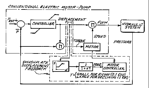
FIG. 4 is a block diagram of a first embodiment of the proposed control
system utilizing swashplate displacement as an element in the feedback
system;
3
CA 02213457 1997-08-20
WO 96/28660 PCT/LTS96/03527
FIG. 5 is a block diagram of a second embodiment of the proposed
control system utilizing motor current in the feedback loop;
FIG. 6 is a diagram showing the portion of the hydraulic pump speed
vs. displacement curve of operation for the first embodiment of the proposed
control system shown in FIG. 4;
FIG. 7 shows graphs illustrative of variable swashplate fast dynamic
response during both load application and removal for the first embodiment
control system of the present invention shown in FIG. 4; and,
FIG 8 shows graphs illustrative of variable swashplate fast dynamic
to response during both load application and removal for the second
embodiment control system of the present invention shown in FIG. 5.
DETAILED DESCRIPTION OF THE DRAWINGS
is Alternative Approaches to Hydraulic Motor-Puma Control
A suitable control approach would involve operating the motor-pump at
a reduced speed when it is lightly loaded (low flow conditions). This would
increase the motor efficiency and pump life while reducing pump noise.
This could be accomplished by introducing a motor controller between
2o the electrical power supply system and the input to the induction motor. At
low-flow conditions, the electric motor-pump would be supplied with
conditioned power from the motor controller which would drive the electric
motor-pump at a low speed. The motor-pump losses and the hydraulic pump
noise would decrease, and hydraulic pump life would increase significantly.
2s During high flow conditions the electric motor-pump would operate at
higher speeds to meet the system requirements. The speed increase would
be due to a change in the conditioned power supplied to the motor by the
motor controller.
Two possible approaches to electric motor-pump control are described
3o hereinafter. The Fixed Displacement Hydraulic Pump/Variable Speed Motor
describes a control technique using a fixed displacement hydraulic pump with
a variable speed motor. The Variable Displacement Hydraulic Pump/Variable
Speed Motor describes first and second embodiments of the proposed control
technique using a variable displacement pump and a variable speed motor.
3s Comparison of these methods shows that the fixed-displacement
pump/variable-speed motor has significant operational problems, while either
version of the variable-displacement pumplvariable-speed motor offers the
best solution.
4
CA 02213457 1997-08-20
WO 96/28660 PC'T/US96/03527
Fixed Displacement Hydraulic PumaNariable Speed Motor
One possible method to control the motor-pump would be to fix the
position of the swashplate in the hydraulic pump and, therefore, make the
s pump flow a function of motor speed only. FIG. 3 indicates the portion of
the
hydraulic pump speed vs. displacement curve on which this system would
operate. This could be made to satisfy the steady-state flow requirements.
However, this approach has some serious problems as described below.
The first item of concern is that operating a fixed displacement pump
to into a fixed pressure system will require the electric motor to supply
rated
torque, hence, to draw rated cun-ent at all times. This may result in
excessive
heat and stress in the motor and its controller.
A second item of concern is that when very low flow is required by the
system the motor speed would be very low (<5-10%). As a result, hydraulic
is fluid may not provide enough wetness to the hydraulic pump, preventing the
buildup of a film thick enough for adequate lubrication. This may cause
degradation of the pumps life and operational characteristics.
Another factor against this method of control deals with the dynamic
response of the system. Prior systems are able to respond quickly to
2o hydraulic system pressure variations due to the fact that it involves only
the
movement of a small swashplate. However, a hydraulic pump with a fixed
swashplate can only change flow rate via a change in motor-pump speed.
The motor-pump combination represents a relatively large inertia which
translates into a sluggish transient response.
2s A further~problem related to this type of control occurs when a rapid
decrease in flow is commanded by the system. This may be achieved by
quickly slowing the motor-pump combination. However, this represents a
significant reduction of the motor-pumps kinetic energy in a short amount of
time. This rotational energy is converted to regenerative electrical form
which
so then flows into the motor controller. This stresses components in the motor
controller which may require an increase in its size/weight or result in
component failure.
Variable Displacement Hydraulic PumpNariable Speed Motor
ss Control system embodiments according to the proposed method
involve a combination of a variable displacement pump and a variable speed
motor. A motor controller is again required to control the speed of the motor,
however, the flow is also a function of swashplate position which is not
fixed.
CA 02213457 1997-08-20
WO 96/28660 PCT/US96/03527
This method overcomes all of the problems identified for the fixed-
displacement/variable-speed motor control hereinabove discussed, and
provides transient response comparable to that of the prior hydraulic system.
Block diagrams for the first and second embodiments of the present control
system are shown in FIGS. 4 and 5 respectively. Swashplate displacement is
used as an element in the feedback system for the first embodiment in FIG. 4,
while the use of motor current in the feedback loop is featured in the second
embodiment shown in block diagram in FIG. 5.
In the second embodiment shown in FIG. 5 when the motor current, or
to equivalently the motor controller current is used as the primary feedback
signal, an additional pressure feedback would be required to ensure high
speed, hence high flow, operation of the motor-pump for severely depressed
system pressure. Without this loop, the current loop would not quickly
increase the pump speed and flow to restore system pressure since the input
Is power to motor would also be low due to depressed system pressure. Also
note that for nominal hydraulic system pressure, the presser loop would be
inactive.
FIG. 6 indicates the portion of the hydraulic pump speed vs.
displacement curve on which the system would operate for the first
2o embodiment. The speed vs. current curve, which would characterize
operation of the second embodiment, would have a very similar form. The
speed/displacement curve shown is illustrative, however for an actual system,
the curve is designed in accordance with hydraulic systems requirements and
the pumps capability. When the hydraulic system requires a high fluid flow,
2s the motor would operate at a high speed and the pumps swashplate position
would be at full displacement. System operation would then be confined to
the upper right hand region of the curve in FIG. 6. On the other hand, for the
majority of the time the required pump flow is very low, thus the motor speed
can be reduced, as can the pump displacement. The system would then
so operate in the lower left portion of the curve in FIG. 6.
For both embodiments of control, the operation of the motor-pump over
the region of low speed has advantages over that for the fixed displacement
system herein above described. At low flow the motor speed is selected so
as to provide sufficient wetness to the hydraulic pumps for full-film
lubrication.
3s Also, the motor current is no longer required to be near ifs rated value
irrespective of the flow requirement as is the case for fixed displacement
pumps. The swashplate action ensures that the motor-pump would be
unloaded during low flow conditions. The motor and pump can therefore
6
CA 02213457 1997-08-20
WO 96/28660 PCT/US96/03527
operate at a low speed without the motor having to supply a high torque
against the system pressure.
A unique feature of the present control system is that it takes
advantage of the variable swashplate to provide fast dynamic response
s during both load application and removal. This is demonstrated by computer
simulation results shown in FIGS. 7 and 8 for the first and second
embodiments respectively. Prior to load application the mofor is assumed to
be running at approximately 40% speed, and the swashplate is at a low value
of displacement. Operation is in the lower left hand region of FIG. 6. When
io flow is demanded, the swashplate quickly moves to increase pump flow to
maintain system pressure. Meanwhile, the motor speed increases at a
somewhat slower rate and eventually reaches an optimum value.
Coordination between the motor speed and swashplate position automatically
occurs during the motors speed increase to maintain system pressure and
is flow.
Similarly, when flow demand increases, the swashplate rapidly moves
to a position consistent with the flow requirements while the motor speed
decreases at a much slower rate. This gradual decrease in motor speed
precludes regenerative energy problems which occur for the fixed
2o displacement system. Changes in motor speed and swashplate position is
again automatically coordinated to achieve proper operation on the lower left
portion of the speed vs. displacement curve. As the simulation results
indicate, the motor-pump transient performance is very close to that for the
prior system shown in FIG. 2 .
2s An added advantage of using a motor controller is that starting an
electric motor-pump would no longer result in a high starting current. The
motor controller would allow the induction motor to accelerate via a "soft
startup" with a negligible impact on the electrical power system. Starting of
multiple motors from a single source would then not require additional
so components to control the starting sequence of the motors in the system.
As seen from the preceding, the present control system embodiments
maintain good transient and steady-state system performance.