Note: Descriptions are shown in the official language in which they were submitted.
CA 02213699 1997-08-22
W O96/27184 PCTrUS9C~ 38
A COMMUNICATION SYSTEM AND METHOD USING A
SPEAKER DEPENDENT TIME-SCALING TECHNIQUE
5 Technical Field
This invention relates generally to voice compression and expansion
techniques, and more particularly to a method and apparatus of voice
compression and expansion using a modified version of Waveform
Similarity based Overlap-Add technique (WSOLA).
1 0
Back~round
Transmission or manipulation of voice signals in applications that
have limited bandwidth or memory typically results in tradeoffs that reduce
quality in the resultant voice output signal or reduce flexibility in the
15 manipulation of such acoustic signals. The speeding up or slowing down
of music or speech using time-scale modifications (that preferably does not
alter the pitch) has many applications including dictation, voice mail, and
sound track editing to name a few. Another particular application, voice
message paging, is not ecor,omi~ally feasiblv for la.y~ pa~ing ~ystems w,~h
20 current technology. The air time required for a voice page is much more
than that required for a tone"lumeric or alphanumeric page. With current
technology, voice paging service would be economically prohibitive in
comparison to tone, numeric or alphanumeric paging with less than ideal
voice quality reproduction. Another constraint in limiting voice message
25 paging is the bandwidth and the present methods of utilizing the bandwidth
of paging channels. In comparison, the growth of alphanumeric paging has
been constrained by the limited access to a keyboard input device for
sending alphanumeric messages to a paging terminal, either in the form of
- a personal keyboard or a call to an operator center. A voice system
30 overcomes these entry issues since a caller can simply pick up a
telephone, dial access numbers, and speak a message. Further, none of
the present voice paging systems take advantage of Motorola's new high
speed paging protocol structure, also known as FLEXTM.
~ Existing voice paging systems lack many of the FLEXTM protocol
35 advantages including high battery saving ratios, multiple channel scanning
capability, mixing of modes such as voice with data, acknowledge-back
paging (allowing for return receipts to the calling party), location finding
capability, system and frequency reuse, particularly in large metropolitan
CA 02213699 1997-08-22
W O96/27184 PCTrUS96/00838
With respect to the aspect of paging involving time-scaling of voice
signals and to other applications such as dictation and voice mail, current
methods of time-scaling lack the ideal combinations of providing adequate
speech quality and flexibility that allow a designer to optimize the
application within the constraints given. Thus, there exists a need for a
voice communication system that is economically feasible and flexible in
allowing optimization within a given configuration, and more particularly
with respect to paging applications, that further retains many of the
advantages of Motorola's FLEXTM protocol.
1 0
$ummary of the Invention
A method for time-scale modification of speech using a modified
version of the Waveform Similarity based Overlap-Add technique (WSOLA)
comprises the steps of storing a portion of an input speech signal in a
memory, analyzing the portion of the input speech signal providing an
estimated pitch value, determining a segment size in response to the
estimated pitch value and time-scaling the input speech signal for a given
time-scaling factor and in response to the determined segment size.
In another aspect of the present invention, a communication system
using voice compression having at least one transmitter base station and a
plurality of selective call receivers comprises at a processing device for
compressing the audio signal using a WSOLA-SD technique and a
quadrature amplitude modulation technique to provide a processed signal
and a quadrature amplitude modulation transmitter for transmitting the
processed signal. And at each of the plurality of selective call receivers, a
selective call receiver module for receiving the transmitted processed
signal, a processing device for demodulating the received processed
signal using a quadrature amplitude demodulation technique and a
WSOLA-SD expansion technique to provide a reconstructed signal.
In another aspect of the present invention, a selective call receiver for
receiving compressed voice signals comprises a selective call receiver for
receiving a transmitted processed signal, a processing device for
demodulating the received processed signal using a single side band
demodulation technique and a WSOLA-SD expansion technique to
provide a reconstructed sig .al.
In yet another aspect of the present invention, an electronic device that
uses a modified version of the Waveform Similarity based Overlap-Add
CA 02213699 1997-08-22
W O96127184 PCTAJS~Gf~
techhique (WSOLA) for time-scale or frequency-scale modification of
speech, comprises a memory for storing a portion of an input speech
signal, a processor for analyzing the portion of the input speech to provide
an estimated pitch value and for further determining a segment size in
5 response to the estimated pitch value, and a device for time-scaling or
frequency-scaling the input speech signal in response to the determined
segment size.
Brief Description of the Drawings
FIG. 1 is a block diagram of a voice communication system in
accordance with the present invention.
FIG. 2 is a block diagram of a base station transmitter in accordance
with the present invention.
FIG. 3 is an expanded electrical block diagram of the base station
transmitter in accordance with the present invention.
FIG. 4 is an expanded electrical block diagram of another base station
transmitter in accordance with the present invention.
FIG. 5 is block diagram of a speech processing, encoding, and
modulation portion of a base station transmitter in accordance with the
present invention.
FIG.6 is a spectrum analyzer output of a 6 single-sideband signal
transmitter in accordance with the present invention.
FIG. 7 is an expanded electrical block diagram of a selective call
receiver in accordance with the present invention.
FIG. 8 is an expanded electrical block diagram of another selective
call receiver in accordance with present invention.
FIG. 9 is an expanded electrical block diagram of another selective
call receiver in accordance with present invention.
FIG. 10 is a timing diagram showing the transmission format of an
outbound signaling protocol in accordance with the present invention.
FIG. 11 is another timing diagram showing the transmission format of
an outbound signaling protocol including details of a voice frame in
accordance with the present invention.
FIG. 12 is another timing diagram illustrating a control frame and two
analog frames of the outbG~nd signaling protocol in accordance with the
present invention.
CA 022l3699 l997-08-22
W O 96/27184 PCTrUS~ 3
FlGs.13-17 illustrate timing diagrams for several iterations of the
WSOLA time-scaling (compression) method in accordance with the present
invention .
FlGs.18-22 illustrate timing diagrams for several iterations of the
5 WSOLA-SD time-scaling (compression) method in accordance with the
present invention.
FlGs. 23-24 illustrate timing diagrams for iterations of the WSOLA-SD
time-scaling (expansion) method in accordance with the present invention.
FIG. 25 illustrates a block diagram of the overall WSOLA-SD time
10 scaling method in accordance with the present invention.
Detailed Description of the Preferred Embodiment
Referring to FIG.1, a communication system illustrative of the voice
compression and expansion techniques of the present invention are shown
15 in a block diagram of the selective call system 100 which comprises an
input device for receiving an audio signal such as telephone 114 from
which voice based selective calls are initiated for transmission to selective
call receivers in the system 100. Each selective call entered through the
telephone 114 (or other input device such as a computer) typically
20 comprises (a) a receiver address of at least one of the selective call
receivers in the system and (b) a voice message. The initiated selective
calls are typically provided to a transmitter base station or a selective call
terminal 113 for formatting and queuing. Voice compression circuitry 101
of the terminal 113 serves to compress the time length of the provided voice
25 message (the detailed operation of such voice compression circuitry 101 is
discussed in the following description of FlGs.2, 3 and 4). Preferably, the
voice compression circuitry 101 includes a processing device for
compressing the audio signal using a time-scaling technique and a single
sideband modulation technique to provide a processed signal. The
30 selective call is then input to the selective call transmitter 102 where it is
applied as modulation to a radio frequency signal which is sent over the air
through an antenna 103. Preferably, the transmitter is a quadrature
amplitude modulation transmitter for transmitting the processed signal.
An antenna 104 within a selective call receiver 112 receives the
35 modulated, transmitted radia frequency signal and inputs it to a selective
call receiver module or radio frequency receiver module 105 for receiving
the processed signal or radio frequency signal, where the radio frequency
CA 02213699 1997-08-22
W ~96127~4 PCT/U~
signal is demodulated and the receive~ address and the compressed voice
message modulation are recovered. The compressed voice message is
then provided to an analog to digital converter (A/D) 115. Preferably, the
selective call receiver 112 includes a processing device for demodulating
5 the received processed signal using a single sideband demodulation
technique and a time-scaling expansion technique to provide a
reconstructed signal. The compressed voice message is then provided to a
voice expansion circuit 106 where the time length of the voice message is
preferably expanded to the desired value (the detailed operation of such
10 voice expansion circuitry 106 used in the present invention is discussed in
the following description of Fl~3s. 7 and 8). The voice message is then
provided to an amplifier such as audio amplifier 108 for the purpose of
amplifying it to a reconstructed audio signal.
The demodulated receiver address is supplied from the radio
frequency receiver 105 to a decoder 107. If the receiver address matches
any of the receiver addresses stored in the decoder 107, an alert 1 1 1 is
optionally activated, providing a brief sensory indication to the user of the
selective call receiver 112 that a selective call has been received. The brief
sensory indication may comprise an audible signal, a tactile signal such as
20 a vibration, or a visual signal such as a light, or a combination thereof. The
amplified voice message is then furnished from the audio amplifier 108 to
an audio loudspeaker within the alert 111 for message announcement and
review by the user.
The decoder 107 may comprise a memory in which the received voice
25 messages can be stored and recalled repeatedly for review by actuation of
one or more controls 110.
In another aspect of the invention, portions of FIG. 1 can be equally
interpreted as part of a dictation device, voice mail system, answering
machine, or sound track editing device for example. By removing the
30 wireless aspects of the system 100 including the removal of selective call
transmitter 102 and radio frequency receiver 105, the system can be
optionally hardwired from the voice compression circuitry 101 to the voice
expansion circuitry 106 through the A/D 115 as shown with the dashed line.
Thus, in a voice mail, answering machine, sound track editing or dictation
35 system, an input device 11~ would supply an acoustic input signal such as
a speech signal to the terminal 113 having the voice compression circuitry
101. The voice expansion circuitry 106 and controls 110 would supply the
CA 02213699 1997-08-22
W O96/27184 PCTrUS96100838
means of listening and manipulating to the output speech signal in a voice
maiJ, answering machine, dictation, sound track editing or other applicable
system. This invention clearly contemplates that the time-scaling
techniques of the claimed invention has many other applications besides
5 paging. The paging example disclosed herein is merely illustrative of one
of those applications.
Now referring to FIG. 2, there is shown a block diagram of a paging
transmitter 102 and terminal 113 including an amplitude compression and
filtering module 150 coupled to a time compression module 160 which is
1 0 coupled to the selective call transmitter 102 and which transmits messages
using aerial or antenna 103. Referring to FlGs . 3 and 4, a lower level block
diagram of the block diagram of FIG. 2 is shown.
Please keep in mind that this compressed voice paging system is
highly bandwidth efficient and intended to support typically 6 to 30 voice
15 messages per 25 kHz channel using the basic concepts of quadrature
amplitude (QAM) or single-side band (SSB) modulation and time scaling of
speech signals. Preferably, in a first embodiment and also referring to FIG.
6, the compressed voice channel or voice communication resource
consists of 3 sub-channels that are separated by 6250 Hz. Each sub-
20 channel consists of two side-bands and a pilot carrier. Each of these two
side-bands may have the same message in a first method or separate
speech messages on each sideband or a single message split between the
upper and lower sidebands in a second method (all intended for the same
receiver or different receivers as desired and designed). The single sub-
25 channel has a bandwidth of substantially 6250 Hz with each side-band
occupying a bandwidth of substantially 3125 Hz. The actual speech
bandwidth is substantially 300-2800Hz. Alternatively, the quadrature
amplitude modulation may be used where the two independent signals are
transmitted directly via I and a components of the signal to form each sub-
30 channel signal. The bandwidth required for transmission is the same in theQAM and SSB cases.
Note that modules 150 and 160 in FIG. 2 can be repeated for use by
each different voice signal (up to 6 times in 25 KHz wide channels and up
to 14 times in 50KHz wide channels) to allow for the efficient and
35 simultaneous transmission of (up to 6 in examples shown) voice messages.
They can all then be summed at a summing device (not shown, but see
FIG. 5) and preferably processed as a composite signal in 102. A separate
,
CA 02213699 1997-08-22
W O 96/2718~ PCTrUS9G~
signai (not shown) contains the FM modulation of the FLEXTM protocol (as
will be described later) which may optionally be generated in software or as
a hardware FM signal exciter.
Preferably, in the examples shown herein, an incoming speech
message is received by the terminal 113. The present system preferably
uses a time-scaling scheme or technique to achieve the required
compression. The preferred compression technique used in the present
invention requires certain parameters specific to the incoming message to
provide an optimum quality. Preferably, the technique of time-scale
compression processes the speech signal into a signal having the same
bandwidth characteristics as uncompressed speech. (Once these
parameters are computed, speech is compressed using the desired time-
scaling compression technique). This time-scaled compressed speech is
then encoded using a digital coder to reduce the number of bits required to
be distributed to the transmitters. In the case of a paging system, the
encoded speech distributed to the transmitters of multiple simulcasting sites
in a simulcasting paging system would need to be decoded once again for
further processing such as amplitude compression. Amplitude
compression of the incoming speech signals (preferably using a syllabic
compander) is used at the transmitter to give protection against channel
impairments.
A time scaling technique known as Waveform Similarity based
Overlap-Add technique or WSOLA encodes speech into an analog signal
having the same bandwidth characteristics as uncompressed speech. This
property of WSOLA allows it to be combined with SSB or QAM modulation
such that the overall compression achieved is the product of the bandwidth
compression ratio of multiple ~AM or SSB subchannels (in our example, 6
voice channels) and the time compression ratio of WSOLA (typically
between 1 and 5). In the present invention, a modified version of WSOLA,
later described and referred to as "WSOLA-SD" is used. WSOLA-SD
retains the compatibility characteristics of WSOLA that allows the
combination with SSB or QAMI modulation.
- Preferably, an Adaptive Differential Pulse Coded Modulation coder
(ADPCM) is used to encode the speech into data that is subsequently
t 35 distributed to the transmitters. At the transmitter, the digital data is decoded
to obtain WSOLA-SD compressed speech which is then amplitude
companded to provide protection against channel noise. This signal is
CA 02213699 1997-08-22
W O96/27184 PCTrUS96/00838
Hilbert transformed to obtain a single-sideband signal. Alternatively, the
signal is quadrature modulated to obtain a QAM signal. A pilot carrier is
then added to the signal and the final signal is interpolated, preferably, to a
16 kHz sampling rate and converted to analog. This is then modulated and
transmitted.
The present invention can operate as a mixed-mode (voice or digital)
one or two way communications system for delivering analog voice and/or
digital messages to selective call receiver units on a forward channel
(outbound from the base transmitter) and for receiving acknowledgments
10 from the same selective call receiver units which additionally have optional
transmitters (on an optional reverse channel (inbound to a base receiver).
The system of the present invention preferably utilizes a synchronous frame
structure similar to FLEXTM (a high speed paging protocol by Motorola, Inc.
and subject of U.S. Patent No. 5,282,205, which is hereby incorporated by
15 reference) on the forward channel for both addressing and voice
messaging. Two types of frames are used: control frames and voice
frames. The control frames are preferably used for addressing and delivery
of digital data to selective call receivers in the form of portable voice units
(PVU's). The voice frames are used for delivering analog voice messages
20 to the PVU's. Both types of frames are identical in length to standard
FLEXTM frames and both frames begin with the standard FLEXTM
synchronization. These two types of frames are time multiplexed on a
single forward channel. The frame structure for the present invention will
be discussed in greater detail later on with regard to FlGs.10,11, and 12.
With regard to modulation, two types of modulation are preferably
used on the forward channel of the present invention: Digital FM (2-level
and 4-level FSK) and AM (SSB or QAM with pilot carrier). Digital FM
modulation is used for the sync portions of both types of frames, and for the
address and data fields of the control frames. AM modulation (each
30 sideband maybe used independently or combined together in a single
message) is used in the voice message field of the voice frames. The
digital FM portions of the transmission support 6400 BPS (3200 Baud
symbols) signaling. The AM portions of the transmissions support band
limited voice (2800 Hz) and require 6.25 KHz for a pair of voice signals.
35 The protocol, as will be shc ~/n later, takes advantage of the reduced AM
bandwidth by subdividing a full channel into 6.25 KHz subchannels, and by
using each subchannel and the AM sidebands for independent messages.
CA 02213699 1997-08-22
W O 96/27184 PCTrUS~G~ 38
Voice System of the present invention is preferably designed to
operate on either 25 KHz or 50 KHz forward channels, but other size
spectrum is certainly within contemplation of the present invention. A 25
KHz forward channel supports a single FM control signal during control
frames, and up to 3 AM subchannels (6 independent signals) during the
message portion of voice frames. A 50 KHz forward channel supports two
FM control signals operated in time lock during control frames, and up to 7
AM subchannels (14 independent signals) during the message portion of
voice frames. Of course, other configurations using different size
bandwidths and numbers of subchannels and signals are contemplated
within the present invention. The examples disclosed herein are merely
illustrative and indicative of the potential broad scope of the claims herein.
In addition to the spectrum efficiency achieved through modulation
and sub-channelization of the spectrum, the present invention, in another
embodiment, can utilize a speaker dependent voice compression
technique that time scales the speech by a factor of 1 to 5 times. By using
both AM sidebands (alternatively, the 2 QAM components) of a subchannel
for different portions of the same message or different messages, the
overall compression factor per subchannel is 2 to 10 times. Voice quality
will typically decrease with an increasing time-compression factor. The
compression technique preferably used in the voice system of the present
invention is a modified form of a known time-scaling technique known as
Waveform Similarity based Overlap-Add technique (WSOLA) as previously
mentioned. The modified form of WSOLA is dependent upon the particular
speaker or speech used, hence the name 'WSOLA-SD" for "WSOLA-
Speaker dependent", which will be discussed later on.
Operation of the present invention is enhanced when a reverse
(inbound to the base receiver) channel is available. The frequency division
simplex mode of operation is one inbound operating mode supported.
(U.S. Patent Nos. 4,875,038 and 4,882,579, both assigned to assignee of
the present invention, Motorola, Inc., illustrate the use of multiple
acknowledge signals on an inbound channel and are incorporated herein
by reference). In frequency division simplex, a separate dedicated channel
(usually paired with the outbound channel) is provided for inbound
transmissions. Inbound da.a rates of 800 to 9600 BPS are contemplated
within a channel bandwidth of 12.5 KHz.
CA 02213699 1997-08-22
W O96/Z7184 PCTrUS96/00838
~ The system of the present invention can be operated in one of several
modes depending on the availability of a reverse channel. When no
reverse channel is available, the system is preferably operated in simulcast
mode for both addressing and voice messaging. When a reverse channel
5 is provided, the system can be operated in a targeted message mode
whereby the messages are broadcast only on a single or a subset of
transmitters located near the portable voice unit. The targeted message
mode is characterized by simulcast addressing to locate the portable voice
unit. The portable voice unit's response on the reverse channel provides
10 the location, followed by a localized message transmission to the portable
voice unit. The targeted message mode of operation is advantageous in
that it provides the opportunity for subchannel reuse; and consequently,
this mode of operation can lead to increased system capacity in many large
systems.
FIG. 3 illustrates a block diagram of a first embodiment of a transmitter
300 in accordance with the present invention. An analog speech signal is
input to an anti-aliasing low pass filter 301 which strongly attenuates all
frequencies above one-half the sampling rate of an analog-to-digital
converter (ADC) 303 which is further coupled to the filter 301. The ADC
303 preferably converts the analog speech signal to a digital signal so that
further signal processing can be done using digital processing techniques.
Digital processing is the preferred method, but the same functions could
also be performed with analog techniques or a combination of analog and
digital techniques.
A band pass filter 305 coupled to the ADC 303 strongly attenuates
frequencies below and above its cutoff frequencies. The lower cutoff
frequency is preferably 300 Hz which allows the significant speech
frequencies to pass, but attenuates lower frequencies which would
interfere with a pilot carrier. The upper cutoff frequency is preferably 2800
Hz which allows the significant speech frequencies to pass but attenuates
higher frequencies which would interfere with adjacent transmission
channels. An automatic gain control (AGC) block 307 preferably coupled
to the filter 305 equalizes the volume level of different voices.
A time compression block 309 preferably coupled to the AGC block
307 shortens the time requi,ed for transmission of the speech signal while
maintaining essentially the same signal spectrum as at the output of the
bandpass filter 305. The time compression method is preferably WSOLA-
CA 02213699 1997-08-22
W O961271~ PCT/U~,C/~C
1 1
SD tas will be explained later on), but other methods could be used. An
amplitude compression block 311, and the corresponding amplitude
expansion block 720 in a receiver 700 (FIG. 7), form a companding device
which is well known to increase the apparent signal-to-noise ratio of the
received speech. The companding ratio is preferably 2 to 1 in decibels, but
other ratios could be used in accordance with the present invention. In the
particular instance of a communication system such as a paging system,
the devices 301-309 may be included in a paging terminal (113 of FIG. 1)
and the remaining components in FIG. 3 could constitute a paging
transmitter (102 of FIG. 1). In such a case, there would typically be a digital
link between the paging terminal and paging transmitter. For instance, the
signal after block 309 could be encoded using a pulse code modulation
(PCM) technique and then subsequently decoded using PCM to reduce the
number of bits transferred between the paging terminal and paging
1 5 transmitter.
In any event, a second band pass filter 308 coupled to the amplitude
compression block 311 stron!aly attenuates frequencies below and above
its cutoff fre,quencies to remo~e any spurious frequency components
generated by the AGC 307, the time compression block 309 or the
amplitude compression block 311. The lower cutoff frequency is preferably
300 Hz which allows the significant speech frequencies to pass, but
attenuates lower frequencies which would interfere with the pilot carrier.
The upper cutoff frequency is preferably 2800 Hz which allows the
significant speech frequencies to pass but attenuates higher frequencies
which would interfere with adijacent transmission channels.
The time compressed speech samples are preferably stored in a
buffer 313 until an entire speech message has been processed. This
allows the time compressed speech message to then be transmitted as a
whole. This buffering method is preferably used for paging service (which
is typically a non real time service). Other buffering methods may be
preferable for other applications. For example, for an application involving
two-way real time conversation, the delay caused by this type of buffering
could be intolerable. In that case it would be preferable to interleave small
segments of several conversations. For example, if the time compression
- 35 ratio is 3:1, then 3 real time speech signals could be transmitted via a
single channel. The 3 transmissions could be interleaved on the channel in
150 millisecond bursts and the resulting delays would not be
CA 02213699 1997-08-22
W O96127184 PCTrUS96tOO~38
12
objectionable. The time compressed speech signal from the buffer 313 is
applied to both to a Hilbert transform filter 323 and to a time delay block
315 which has the same delay as the Hilbert transform filter, but does not
otherwise affect the signal.
The output of the time delay block 315 (through the summing circuit
317) and the Hilbert transform filter 323 form, respectively, the in-phase (I)
and quadrature (Q) components of an upper sideband (USB) single
sideband (SSB) signal. The output of the time delay and the negative (325)
of the Hilbert transform filter form, respectively, the in-phase (I) and
quadrature (Q) components of a lower sideband (LSB) single sideband
signal. Thus the transmission may be on either the upper or lower
sideband, as indicated by the dotted connection.
While the upper sideband is used to transmit one time compressed
speech signal, the lower sideband can be used to simultaneously transmit
a second time compressed speech signal by using another similar
transmitter operating on the lower sideband. SSB is the preferred
modulation method because of efficient use of transmission bandwidth and
resistance to crosstalk. Double sideband Amplitude Modulation (AM) or
frequency modulation (FM) could be used, but would require at least twice
the bandwidth for transmission. It is also possible to transmit one time
compressed speech signal directly via the I component and a second time
compressed speech signal directly via the Q component, however, in the
present embodiment this method is subject to crosstalk between the two
signals when multipath reception occurs at the receiver.
A direct current (DC) signal is added to the I component of the signal
to generate the pilot carrier, which is transmitted along with the signal and
used by the receiver (700) to substantially cancel the effects of gain and
phase variations or fading in the transmission channel. The I and Q
components of the signal are converted to analog form by digital-to-analog
converters (DAC) 319 and 327 respectively. The two signals are then
filtered by low pass reconstruction filters 321 and 329 respectively to
remove spurious frequency components resulting from the digital-to-analog
conversion process. A quadrature amplitude modulation (QAM) modulator
333 modulates the I and Q signals onto a radio frequency (RF) carrier at
low power level. Other mo~ulation methods, e.g., direct digital synthesis of
the modulated signal, would accomplish the same purpose as the DACs
(319 and 327), reconstruction filters (321 and 329), and QAM modulator
CA 02213699 1997-08-22
W O96/27184 PCT~US96/00838
13
333-. Finally, a linear RF power amplifier 335 amplifies the moduiated RF
signal to the desired power llsvel, typically 50 watts or more. Then, the
output of the RF power amplifier 335 is coupled to the transmitting antenna.
Other variations can produce essentially the same results. For example, the
amplitude compression could be performed before the time compression,
or omitted altogether and the device would still perform essentially the
same function.
FIG. 4 illustrates a blocl~ diagram of a second embodiment of a
transmitter 400 in accordance with the present invention. In FIG. 4, both the
10 upper and lower sidebands are used to simultaneously transmit different
portions of the same time compressed signal. The transmitter 400
preferably includes an anti-alias filter 404, an ADC 403, a bandpass filter
405, an AGC 407, a time compression block 409, an amplitude
compression block 411, and a bandpass filter 408 coupled and configured
15 as in FIG. 3. Operation of the transmitter of FIG. 4 is the same as in FIG.3
until an entire speech message has been processed and stored in a buffer
413. The time compressed speech samples stored in the buffer 413 are
then divided to be transmitt~d on either the upper or lower sideband.
Preferably, the first half of the time compressed speech message is
20 transmitted via one sidebanci and the second half of the time compressed
speech message is transmitted via the other sideband (or alternatively on
each of the I and Q components directly).
The first portion of time compressed speech signal from the buffer 413
is applied to both a first Hilbert transform filter 423 and to a first time delay
25 block 415 which has the same delay as the Hilbert transform filter 423 but
does not otherwise affect the signal. The output of the first time delay
(through summing circuit 417) and the first Hilbert transform filter 423
(through summing circuit 465) are In-Phase (I) and Quadrature Phase (Q)
signal components which, when coupled to I and Q inputs of the QAM
30 modulator, generate upper sideband signal having information only from
the first portion of time compressed speech samples. The second time
compressed speech signal from the buffer 413 is applied to both a second
Hilbert transform filter 461 and to a second time delay block 457 which has
the same delay as the Hilbert transform filter 461 but does not otherwise
35 affect the signal. The output of the second time delay (through summing
circuits 459 and 417) and the negative (463) of the output of the second
Hilbert transform filter 461 (and again, through summing circuit 465) are In-
CA 02213699 1997-08-22
W O96/27184 PCTrUS~6/00838
14
Pha-se (I) and Quadrature Phase (Q) signal components which, when
coupled to I and Q inputs of the QAM modulator, generate upper sideband
signal having information only from the second portion of time compressed
speech samples. The I components of the upper and lower sideband
5 signals are added with a DC pilot carrier component (through summing
circuit 459) to form a composite I component for transmission. The Q
components of the upper and lower sideband signals are added (through
summing circuit 465) to form a composite Q component for transmission. It
will be appreciated that elements 415, 423, 457, 461, 417, 459, 463, 465,
1 0 419, 427, 421, and 429 form a preprocessor which generates
preprocessed I and Q signal components, which when coupled to the QAM
modulator 453 generate the low level subchannel signal with a subcarrier
FA, having two single sideband signals, which have independent
information on each sideband.
1 5 The transmitter 400 further comprises DACs 419 and 427,
reconstruction filters 421 and 429, QAM modulator 433, and RF power
amplifier 455 arranged and constructed as described in FIG. 3. Operation
of the rest of the transmitter of FIG. 4 is the same as in FIG. 3.
Preferably, in both transmitters 300 and 400 of FlGs. 3 and 4
respectively, only the anti-alias filters, the reconstruction filters, the RF
power amplifier and optionally the Analog to Digital converter and digital to
analog converters are separate hardware components. The remainder of
the devices can preferably be incorporated into software which could be
run on a processor, preferably a digital signal processor.
FIG. 7 illustrates a block diagram of a receiver 700 which preferably
operates in conjunction with the transmitter 300 of FIG. 3 in accordance
with the present invention. A receiving antenna is coupled to a receiver
module 702. The receiver module 702 includes conventional receiver
elements, such as RF amplifier, mixer, bandpass filter, and intermediate
frequency (IF) amplifier (not shown). A QAM demodulator 704 detects the I
and Q components of the received signal. An analog-to-digital converter
(ADC) 706 converts the I and Q components to digital form for further
processing. Digital processing is the preferred method, but the same
functions could also be performed with analog techniques or a combination
of analog and digital technklues. Other methods of demodulation, e.g., a
sigma-delta converter, or direct digital demodulation, would accomplish the
same purpose as the QAM demodulator 704 and ADC 706.
CA 02213699 1997-08-22
W O96/27184 P ~ AUS~6/00~38
-- A feedforward automatic gain control (AGC) block 708 uses the pilot
carrier, transmitted along with the time compressed speech signal, as a
phase and amplitude reference signal to substantially cancel the effects of
amplitude and phase distortions occurring in the transmission channel. The
outputs of the feedforward automatic gain control are corrected I and Q
components of the received signal. The corrected Q component is applied
to a Hilbert transform filter 712, and the corrected I component is applied to
a time delay block 710 which has the same delay as the Hilbert transform
filter 712 but does not otherwise affect the signal.
If the time compressed speech signal was transmitted on the upper
sideband, the output of the Hilbert transform filter 712 is added (through
summing circuit 714) to the output of the time delay block 710 to produce
the recovered time compressed speech signal. If the time compressed
speech signal was transmitted on the lower sideband, the output of the
1 5 Hilbert transform filter 712 is subtracted (716) from the ou~put of the timedelay block 710 to produce the recovered time compressed speech signal.
The recovered time compressed speech signal is preferably stored in a
buffer 718 until an entire message has been received. Other buffering
methods are also possible. (See the discussion with FIG. 3.)
An amplitude expansion block 720 works in conjunction with the
amplitude compression block 311 of FIG. 3 to perform the companding
function. A time expansion block 722 works in conjunction with the time
compression block 309 of Fl(3. 3 and preferably reconstructs the speech
into its natural time frame (for audio output through a transducer 724) or
other time frames as other applications may suggest. One application
could optionally include the transfer of digitized voice to a computing
device 726, where the receiver-to-computer interface can be a PCMCIA or
RS-232 interface or any number of interfaces known in the art. The time
compression method is preferably WSOLA-SD, but other methods could be
used, so long as complementary methods are used in the transmitter and'
receiver. Other variations in configuration can produce essentially the
same results. For example, the amplitude compression could be performed
after the time compression, or omitted altogether and the device would still
perform essentially the same function.
- 35 FIG. 8 illustrates a blo~k diagram of a receiver 750 which operates in
conjunction with the transmitter of FIG. 400 in accordance with the present
invention. The receiver of FIGJ. 8 comprises an antenna, receiver module
CA 022l3699 l997-08-22
W O 96/27184 PCTrUS96/00838
16
752; a QAM modulator 754, an ADC 756, a Feed-forward AGC 758, a time
delay block 760, and a Hilbert transform filter 762 arranged and
constructed as described in FIG. 7. Operation of the receiver of FIG. 8iS the
same as FIG. 7, up to the output of the time delay block 760 and Hilbert
transform filter 762. The output of the Hilbert transform filter 762iS added to
the output of the time delay block 760 (through summing circuit 764) to
produce the recovered time compressed speech signal corresponding to
the first half of the speech message which was transmitted on the upper
sideband. The output of the Hilbert transform filter 762iS subtracted (766)
10 from the output of the time delay block 760 to produce the recovered time
compressed speech signal corresponding to the second half of the speech
message which was transmitted on the lower sideband.
The two recovered time compressed speech signals are stored in
either respective upper sideband and lower sideband buffers 768 or 769
15 until the entire message has been received. Then, the signal
corresponding to the first half of the message and the signal corresponding
to the second half of the message are applied sequentially to the amplitude
expansion block 770. An amplitude expansion block 770 works in
conjunction with the amplitude compression block 411 of FIG. 4 to perform
20 the companding function.
The operation of the rest of the receiver of FIG. 8 is the same as FIG. 7.
A time expansion block 772 works in conjunction with the time
compression block 409 of FIG. 4 and preferably reconstructs the speech
into its natural time frame or other time frames as other applications may
25 suggest or require. The time compression method is preferably WSOLA-
SD, but other methods could be used, so long as complementary methods
are used in the transmitter and receiver. Other configurations can produce
essentially the same results. For example, the amplitude compression
could be performed after the time compression, or omitted altogether and
30 the device would still perform essentially the same function.
As with the implementation of the transmitters of FlGs. 3 and 4, many
of the components in FlGs. 7 and 8 can be implemented in software
including, but not limited to the AGCs, the single-sideband or QAM
demodulators, summation circuits, the amplitude expansion blocks, and the
35 time expansion blocks. Al! the other components are preferably
implemented in hardware.
CA 022l3699 l997-08-22
W O96/27184 PCTAUS96/00838
17
- If the speech processing, encoding and modulation portion of the
present invention were to be implemented into hardware, the
implementation of FIG. 5 could be used. For instance, transmitter 500 of
FIG. 5 would include a series of pairs of single-sideband exciters (571-576)
set to the frequencies of their respective pilot carriers (581-583). Exciters
571-576 and pilot carriers 581-583 correspond to the separate voice
processing paths. All these signals, including a signal from an FM signal
exciter 577 (for the digital FM modulation used for the synchronization,
address and data fields previously described) would be fed into a summing
amplifier 570 which in turn is amplified by a linear amplifier 580 and
subsequently transmitted. The low level output of FM exciter 577iS also
linearly combined in summing amplifier 570. The composite output signal
of summing amplifier 570iS amplified to the desired power level, usually 50
watts or more, by linear RF power amplifier 580. The output of linear RF
power amplifier 580iS then coupled to the transmitting antenna.
Other means could be used to combine several subchannel signals.
For example, the several digital baseband I and Q signals, obtained at the
outputs of 417 and 465 in Fi~g. 4, could be translated in frequency to their
respective subcarrier offset frequencies, combined in digital form, then
converted to analog form for modulation onto the carrier frequency.
Referring to FIG. 9, there is shown another receiver unit 900 in
accordance with the present invention. Receiver 900 additionally
incorporates a means for detecting and decoding the FM modulated control
signals that are used in the FLEXTM signaling protocol. Block 902 is the
receiver front end and an Flvl back end. A digital automatic frequency
- controller (DAFC) and automatic gain controller (AGC) are incorporated
into block 902. Block 906 includes the radio processor with a support chip
950 and Blocks 911,914, and 916 include all the output devices. Block
904 is the battery saver or battery economy circuit which operates under
control of the processor 906. Block 850iS the linear decoder followed by
an analog-to-digital converter and random access memory (RAM) Block
868. The receiver Block 902 is preferably a modified FM receiver including
~ the addition of a DAFC as described in U.S. Patent No. 5,239,306 (which is
assigned to the assignee of the present invention and which is hereby
- 35 incorporated by reference herein), an AGC, and which provides for an
intermediate frequency (IF) output at a point following most of the receiver
gain but prior to the FM demodulator.
CA 02213699 1997-08-22
W O96/27184 PCTrUS96/OQY38
18
The same processor that controls Motorola's FLEXTM protocol
compatible pagers would adequately handle all the protocol functions in
the present invention including the address recognition and message
decoding of an FM demodulated signal. Additionally, in response to an FM
5 modulated address (and perhaps message pointer code words), the
processor 906 initiates the operation of the analog-to-digital conversion
and of the RAM Block 868. Block 868 samples either or both the I (In-
phase) and Q (quadrature) linearly modulated signals at the outputs of the
linear decoder block 850. The signal samples are written directly to RAM
10 with the aid of an address counter and in response to a control signal from
the processor 906.
A voice can be sent as an SSB signal occupying a single voice
bandwidth on the channel, or equivalently on either of the I or Q channels
as was described earlier. Each of the I and Q signals simultaneously
15 occupy the same RF bandwidth as two analog-single sidebands (SSB).
Voice bandwidths are on the order of 2.8KHz, so a typical signal sampling
rate of about 6.4 KHz each is required of the analog-to-digital converter if
analog-SSB is recovered from the I and Q channel information. The
analog-to-digital converter samples with 8 bit precision (although as much
20 as 10 bits is preferred). Direct memory access by the analog-to-digital
converter allows the use of a processor whose speed and power are not a
direct function of the channel data rate. That is, a microprocessor can be
used with direct memory access, whereas, a significantly higher speed
processor would be required if the analog-to-digital converted data were
25 read to memory through the microprocessor.
The analog-to-digital converter (A/D), the dual port RAM and the
address counter are grouped as block 868. A second RAM ItO port can be
serial or parallel, and operates at a 6 or 12 K sample per second rate. A
second RAM l/O port is provided so that the processor can extract the
30 sampled voice or data, process the demodulation function, and expand the
compressed voice or format the data. The restored voice is played back
through the voice processor 914 and transducer 916, while formatted data
can be displayed on display 911.
Again, referring to FIG. 9, an expanded electrical block diagram is
35 used to describe in further ~etail the receiver operation of the dual mode
communication receiver of the present invention. The transmitted
information signal, modulated in the FM modulation format, or in a linear
CA 02213699 1997-08-22
W O 96/27184 P ~ ~US96/0~838
19
modulation format (such as SSB), is intercepted by the antenna 802 which
couples the information signal to the receiver section 902, and in particular
to the input of the radio frequency (RF) amplifier 806. The message
information is transmitted on any suitable RF channel, such as those in the
5 VHF bands and UHF bands. The RF amplifier 806 amplifies the received
information signal, such as that of a signal received on a 930 MHz paging
- channel frequency, coupling the amplified information signal to the input of
the first mixer 808. The first oscillator signal, which is generated in the
preferred embodiment of the present invention by a frequency synthesizer
or local oscillator 810, also couples the first mixer 808. The first mixer 808
mixes the amplified information signal and the first oscillator signal to
provide a first intermediate frequency, or IF, signal, such as a 45 MHz IF
signal, which is coupled to the input of the first IF filter 812. It will be
appreciated that other IF frequencies can be utilized as well, especially
when other paging channel frequencies are utilized. The output of the IF
filter 812 which is the on-channel information signal, is coupled to the input
of the second conversion section 814, which will be described in further
detail below. The second conversion section 814 mixes the on-channel
information signal to a lower intermediate frequency, such as 455KHz,
using a second oscillator signal, which is also generated by the synthesizer
810. The second conversion section 814 amplifies the resultant
intermediate frequency signal, to provide a second IF signal which is
suitable to be coupled to either the FM demodulator section 908 or to the
linear output section 824.
Receiver section 804 operates in a manner similar to a conventional
FM receiver, however, unlike a convention FM receiver, the receiver section
804 of the present invention also includes an automatic frequency control
section 816 which is coupled to the second conversion section 814, and
which appropriately samples the second IF signal to provide a frequency
correction signal which is coupled to the frequency synthesizer 810 to
maintain the receiver tuning to the assigned channel. The maintenance of
receiver tuning is especially important for the proper reception of QAM (that
is, I and Q components) and/or SSB information which is transmitted in the
linear modulation format. The use of a frequency synthesizer to generate
the first and second oscillator frequencies enables the operation selection
of the receiver on multiple operating frequencies, selected such as by code
memory programming and/or by parameters received over the air, as for
CA 02213699 1997-08-22
W O96/27184 PCTrUS~G/OQ838
example, in the FLEXTM protocol. It will be appreciated that other oscillator
circuits, such as fixed frequency oscillator circuits which can be adjusted by
a frequency correction signal from the automatic frequency control section
816, can be utilized as well.
An automatic gain control 820 is also coupled to the second
conversion section 814 of the dual mode receiver of the present invention.
The automatic gain control 820 estimates the energy of samples of the
second IF signal and provides a gain correction signal which is coupled to
the RF amplifier 806 to maintain a predetermined gain for the RF amplifier
10 806. The gain correction signal also couples the second conversion
section 814 to maintain a predetermined gain for the second conversion
section 814. The maintenance of the gain of the RF amplifier 806 and the
second conversion section 814 is required for proper reception of the high
speed data information transmitted in the linear modulation format, and
15 further distinguishes the dual mode receiver of the present invention from a
conventional FM receiver.
When the message information or control data is transmitted in the FM
modulation format, the second IF signal is coupled to the FM demodulator
section 908, as will be explained in detail below. The FM demodulator
20 section 908 demodulates the second IF signal in a manner well known to
one of skill in the art, to provide a recovered data signal, which is a stream
of binary information corresponding to the received address and message
information transmitted in the FM modulation format. The recovered data
signal coupled to the input of a microcomputer 906, which function as a
25 decoder and controller, through an input of inpuVoutput port, or l/O port 828.
The microcomputer 906 provide complete operational control of the
communication receiver 900, providing such functions as decoding,
message storage and retrieval, display control, and alerting, just to name a
few. The device 906 is preferably a single chip microcomputer such as the
30 MC68HC05 microcomputer manufactured by Motorola, and includes CPU
840 for operational control. An internal bus 830 connects each of the
operational elements of the device 906. I/O port 828 (shown split in FIG. 9)
provides a plurality of control and data lines providing communications to
device 906 from external circuits, such as the battery saver switch 904,
35 audio processor 914, a disp!ay 911, and digital storage 868. A timing
means, such as timer 834 is used to generate the timing signals required
for the operation of the communication receiver, such as for battery saver
,
CA 02213699 1997-08-22
W O 96/27184 PCTrU~3~/~0
21
tim;~g, alert timing, and message storage and display timing. Oscillator
832 provides the clock for operation of CPU 840, and provides the
reference clock for timer 834. RAM 838 is used to store information utilized
in executing the various firmware routines controlling the operation of the
5 communication receiver 900, and can also be used to store short
messages, such as numeric messages. ROM 836 contains the firmware
routines used to control the device 906 operation, including such routines
as required for decoding the recovered data signal, battery saver control,
message storage and retrieval in the digital storage section 868, and
10 general control of the pager operation and message presentation. An alert
generator 842 provides an alerting signal in response to decoding the FM
modulated signaling information. A code memory 910 (not shown) couples
the microcomputer 906 through the l/O port 828. The code memory is
preferably an EEPROM (electrically erasable programmable read only
15 memory) which stores one or more predetermined addresses to which
communication receiver 900 is responsive.
When the FM modulated signaling information is received, it is
decoded by the device 906, functioning as a decoder in a manner well
known to one skilled in the art. When the information in the recovered data
20 signal matches any of the stored predetermined addresses, the
subsequently received information is decoded to determine if additional
information is directed to the receiver which is modulated in the FM
modulation format, or if the additional information is modulated in the linear
modulation format. When the additional information is transmitted in the FM
25 modulation format, the reco\rered message information is received and
stored in the microcomputer RAM 838, or in the digital storage section 868,
as will be explained further below, and an alerting signal is generated to
alert generator 842. The alerting signal is coupled to the audio processing
circuit 914 which drives transducer 916, delivering an audible alert. Other
30 forms of sensible alerting, such as tactile or vibrating alert, can also be
provided to alert the user as well.
When additional information is to be transmitted in the linear
modulation format (such as SSB or "I and Q"), the microcomputer 906
decodes pointer information. The pointer information includes information
- 35 indicating to the receiver on what combination of sidebands t or on what
combination of I and Q components) within the channel bandwidth that the
additional information is to be transmitted. The device 906 maintains the
CA 02213699 1997-08-22
W O96/27184 PCTrUS96/00838
22
operation of monitoring and decoding information transmitted in the FM
modulation format, until the end of the current batch, at which time the
supply of power is suspended to the receiver until the next assigned batch,
or until the batch identified by the pointer is reached, during which high
speed data is transmitted. The device 906, through l/O port 828 generates
a battery saving control signal which couples to battery saver switch 904 to
suspend the supply of power to the FM demodulator 908, and to supply
power to linear output section 824, the linear demodulator 850, and the
digital storage section 868, as will be described below.
1 0 The second IF output signal, which now carries the SSB (or "I and Q")
information is coupled to the linear output section 824. The output of the
linear output section 824 is coupled to the quadrature detector 850,
specifically to the input of the third mixer 852. A third local oscillator also
couples to the third mixer 852, which is preferably in the range of
1 5 frequencies from 35-150kHz, although it will be appreciated that other
frequencies may be utilized as well. The signal from the linear output
section 824 is mixed with the third local oscillator signal 854, producing a
third IF signal at the output of the third mixer 852, which is coupled to a third
IF amplifier 856. The third IF amplifier is a low gain amplifier which buffers
the output signal from the input signal. The third output signal is coupled to
an I channel mixer 858 and a Q channel mixer 860. The l/Q oscillator 862
provides quadrature oscillator signals at the third IF frequency which are
mixed with the third output signals in the I channel mixer 858 and the Q
channel mixer 860, to provide baseband I channel signals and Q channel
signals at the mixer outputs. The baseband I channel signal is coupled to a
low pass filter 864, and the baseband Q channel signal is coupled to a low
pass filter 866, to provide a pair of baseband audio signals which represent
the compressed and companded voice signals .
The audio signals are coupled to the digital storage section 868, in
particular to the inputs of an analog to digital converter 870. The A/D
converter 870 samples the signals at a rate at least twice the highest
frequency component at the output of 864 and 866. The sampling rate is
preferably 6.4 kilohertz per I and Q channel. It will be appreciated, that the
data sampling rate indicated is for example only, and other sampling rates
may be used depending upon the bandwidth of the audio message
received.
CA 02213699 1997-08-22
W O96/27184 PCT~USg~ Q~8
23
-- During the batch when the high speed data is transmitted, the
microprocessor 906 provides a count enabling signal which is coupled to
the address counter 872. the A/D converter 870 is also enable to allow
sampling of the information symbol pairs. The A/D converter 870 generates
5 high speed sample clock signals which are used to clock the address
counter 872 which in turn sequentially generates addresses for loading the
sampled voice signals into a dual port random access memory 874 through
data lines going from the converter 870 to the RAM 874. The voice signals
which have been loaded at high speed into the dual port RAM 874 in real
10 time, are processed by the microcomputer 906 after all voice signals have
been received, thereby producing a significant reduction in the energy
consumed by not requiring the microcomputer 906 to process the
information in real time. The microcomputer 906 accesses the stored
signals through data lines and address lines, and in the preferred
15 embodiment of the present invention, processes the information symbol
pairs to generate either ASCII encoded information in the case of
alphanumeric data having been transmitted, or digitized sampled data in
the case voice was transmitted. The digitized voice samples can
alternatively stored in other formats such as BCD, CVSD, or LPC based
20 forms and other types as required. In the case of time compressed voice
signals, the I and Q components sampled by ADC converter 870 are further
processed by CPU 840 via dual port RAM 874 and l/O 828 to (1 ) amplitude
expand the audio signal and (2) time-expand the signal as was described
in the similar operation of the receivers of FlGs. 7 and 8. The voice is then
25 stored again in RAM 874. The ASCII encoded or voice data is stored in the
dual port RAM until the information is requested for presentation by the
communication receiver user. The stored ASCII encoded data is recovered
by the user using switches (not shown) to select and read the stored
messages. When the stored ASCII encoded message is to be read, the
30 user selects the message to be read and actuates a read switch which
enable microcomputer 906 to recover the data, and to present the
recovered data to a display 911, such as a liquid crystal display. When a
voice message is to be read, the user selects the message to be read and
actuates a read switch which enables the microcomputer 906 to recover the
35 data from the dual port RArA, and to present the recovered data to the audio
processor 914 which converts the digital voice information into an analog
voice signal which is coupled to a speaker 916 for presentation of the voice
CA 02213699 1997-08-22
W O96/27184 PCTrUS96/00838
24
message to the user. The microcomputer 906 can also generate a
frequency selection signal which is coupled to frequency synthesizer 810 to
enable the selection of different frequencies as previously described.
Referring to FIG.10, a timing diagram is shown which illustrates
5 features of the FLEXTM coding format on outbound signaling utilized by the
radio communication system 100 of FIG.1, and which includes details of a
control frame 330, in accordance with the preferred embodiment of the
present invention. Control frames are also classified as digital frames.
The signaling protocol is subdivided into protocol divisions, which are an
hour 310, a cycle 320, frames 330, 430 a block 340, and a word 350. Up to
fifteen 4 minute uniquely identified cycles are transmitted in each hour 310.
Normally, all fifteen cycles 320 are transmitted each hour. Up to one
hundred twenty eight 1.875 second uniquely identified frames including
digital frames 330 and analog frames 430 are transmitted in each of the
cycles 320. Normally, all one hundred twenty eight frames are transmitted.
One synchronization and Frame Information signal 331 lasting one
hundred fifteen milliseconds and 11 one hundred sixty millisecond
uniquely identified blocks 340 are transmitted in each of the control frames
330. Bit rates of 3200 bits per second (bps) or 6400 bps are preferably
used during each control frame 330. The bit rate during each control frame
330 is communicated to the selective call radios 106 during the
synchronization signal 331. When the bit rate is 3200 bps, 16 uniquely
identified 32 bit words are included in each block 340, as shown in FIG.10.
When the bit rate is 6400 bps 32 uniquely identified 32 bit words are
included in each block 340 (not shown). In each word, at least 11 bits are
used for error detection and correction, and 21 bits or less are used for
information, in a manner well known to one of ordinary skill in the art. The
bits and words 350 in each block 340 are transmitted in an interleaved
fashion using techniques well known to one of ordinary skill in the art to
improve the error correction capability of the protocol.
Information is included in each control frame 330 in information fields,
comprising Frame structure information in a block information field (Bl) 332,
one or more selective call addresses in an address field (AF) 333, and one
or more vectors in a vector field (VF) 334. The vector field 334 starts at a
vector boundary 334. Each vector in the vector field 334 corresponds to
one of the addresses in the address field 333. The boundaries of the
information fields 332, 333, 334 are defined by block information field 332.
CA 02213699 1997-08-22
W O96127184 PCTAUS96/00838
Information fields 332, 333, 334 are variable, depending on factors such as
the type of system information included in the sync and frame information
field 331 and the number of addresses included in the address field 333,
and the number and type of vectors included in the vector field 334.
Referring to FIG.11, a timing diagram is shown which illustrates
features of the transmission ~ormat of the outbound signaling protocol
utilized by the radio communication system of FIG.1, and which includes
details of a voice frame 430, in accordance with the preferred embodiment
of the present invention. Voice frames are also classified herein as analog
10 frames. The durations of the protocol divisions hour 310, cycle 320, and
frame 330, 430 are identical to those described with respect to a control
frame in FIG. 10. Each analog frame 430 has a header portion 435 and an
analog portion 440. The information in the synchronization and frame
information signal 331 is the same as the synchronization signal 331 in a
15 control frame 330. As described above, the header portion 435 is
frequency modulated and the analog portion 440 of the frame 430, is
amplitude modulated. A transition portion 444 exists between the header
po~jon 435 aPd ar,alog portion 44G, ln ~ccordance with the preferred
embodiment of the present invention, the transition portion includes
20 amplitude modulated pilot subcarriers for up to three subchannels 441,
442, 443. The analog portion 440 illustrates the three subchannels 441,
442, 443 which are transmitted simultaneously, and each subchannel
includes an upper sideband signal 401 and a lower sideband signal 402
(or alternatively, an in-phase and a quadrature signal). In the example
25 illustrated in FIG. 11, the upper sideband signal 401 includes one message
fragment 415, which is a first fragment of a first analog message. Included
in the lower sideband 402 are four quality assessment signals 420, 422,
424, 426, four message segments 410, 412, 416, 418, and one segment
414 (unused in this example). The two segments 410, 412 are segments of
30 a second fragment of the first analog message. The two segments 416,
418 are segments of a first fragment of a second analog message. The first
and second analog messages are compressed voice signals which have
been fragmented for inclusion in the first subchannel 441 of frame one 430
of cycle 2 of 320. The second fragment of the first message and the first
~ 35 fragment of the second me~sage are each split to include a qualityassessment signal 420, 426, which is repeated at predetermined positions
in the lower sideband 402 of each of the three subchannels 441, 442, 443.
CA 02213699 1997-08-22
W O 96/27184 PCTrUS~ Oa38
26
The-smallest segment of message included in an analog frame is defined
as a voice increment 450, of which 88 are uniquely identified in each
analog portion 440 of an analog frame 430. The quality assessment
signals are preferably transmitted as unmodulated subcarrier pilot signals,
5 are preferably one voice increment in duration, and preferably have a
separation of no more than 420 milliseconds within an analog portion of a
frame. It will be appreciated that more than one message fragment could
occur between two quality assessment signals, and that message
fragments are typically of varying integral lengths of voice increments.
1 0 Referring to FIG. 12, a timing diagram illustrating a control frame 330and two analog frames of the outbound signaling protocol utilized by the
radio communication system of FIG. 1 is shown, in accordance with the
preferred embodiment of the present invention. The diagram of FIG.12
shows an example of a frame zero (FIG. 10) which is a control frame 330.
Four addresses 510, 511, 512, 513 and four vectors 520, 521, 522, 523 are
illustrated. Two addresses 510, 511 include one selective call radio 106
address, while the other two addresses 512, 513 are for a second and third
selective call radio 106. Each address 510, 511, 512, 513 is uniquely
associated with one of the vectors 520, 521, 522, and 523 by inclusion of a
pointer within each address which indicates the protocol position of (i.e.,
where the vector starts and how long it is) the associated vector.
In the example shown in FIG. 12, vectors 520, 521, 522, 523 are also
uniquely associated with a message portion in one of the subchannels.
Specifically, vector 520 can point to an upper sideband of subchannel 441
(see FIG. 11) and vector 522 can point to a lower sideband of subchannel
441. Similarly, vector 521 can point to both sidebands of subchannel 442.
That is, in the case of subchannel 441, the example can show that two
different message portions are carried by the upper and lower sidebands.
In the case of subchannel 442, two halves of one message portion are
carried by the upper and lower sidebands respectively. Thus, the vectors
preferably include information therein to indicate which subchannel (i.e.,
which radio frequency) the receiver should look for a message, and also
information to indicate whether two separate messages are to be
recovered from the subchannel, or whether first and second halves of a
single message are to be rccovered.
One use for the embodiment where two different messages are
simultaneously transmitted over upper and lower sidebands (or I and Q
CA 02213699 1997-08-22
W O96/27184 PCTrUS~'00~8 27
channels), respectively, is where one message is a direct voice paging
message, and the other is a voice mailbox message, which is to be stored
in the pager.
In accordance with the preferred embodiment of the present invention
5 the vector position is provided by identifying the number of words 350 after
the vector boundary 335 at which the vector starts, and the length of the
vector, in words. It will be appreciated that the relative positions of the
addresses and vectors are independent for each other. The relationships
are illustrated by the arrows. IEach vector 520, 521, 522, 523 is uniquely
1 0 associated with a message fragment 550, 551, 552, 553 by inclusion of a
pointer within each vector which indicates the protocol position of (i.e.,
where the fragment starts and how long it is) the associated vector. In
accordance with the preferred embodiment of the present invention the
message fragment position is provided by identifying the frame 430
number (from 1 to 127), the subchannel 441, 442, 443 number (from one to
three), the sideband 401, 402, (or I or Q) and the voice increment 450
where the message fragment starts, and the length of the message
fragment, in terms of voice increments 450. For example, vector three 522
includes information which indicates that message two, fragment one 552,
which is intended for selective call transceiver 106 having selective call
address 512, is located starting at voice increment forty six 450 (the voice
increments 450 are not identified in FIG.12) of frame one 560, and vector
thirteen 523 includes information which indicates that message nine
fragment one 553, which is intended for selective call transceiver 106
having selective call address 513, is located starting at voice increment
zero 450 (the voice increments 450 are not shown in FIG.12) of frame five
561
It will be appreciated that, while voice signals are described in
accordance with the preferred embodiment of the present invention, other
analog signals, such as modem signals or dual tone multi-frequency
(DTMF) signals, can alternatively be accommodated by the present
invention. It should also be appreciated that the block information used in
the frame structure previously described can be used to implement further
enhancements that would allow for greater overall throughput in a
- 35 communication system and allow for additional features. For instance, a
message sent to a portable voice unit can request that an acknowledgment
signal sent back to the system include information that would identify the
CA 02213699 1997-08-22
W 096r27184 PCTrUS9GIC~8~8
28
trartsmitter it was receiving its messages from. Thus, frequency reuse in a
sirrlulcast system can be achieved in this way by transmitting messages to
the given portable voice unit using the one transmitter required to reach
the portable voice unit. Additionally, once the system knows the location of
5 the portable voice unit, implementing target messaging logically follows.
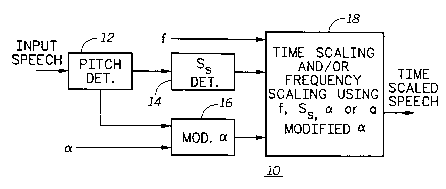
In another aspect of the present invention, the time-scaling technique,
previously described as WSOLA has some existing disadvantages when
used in conjunction with the present invention. Thus, a technique was
developed that modifies WSOLA to become speaker dependent and
10 appropriately named "WSOLA-SD". To further understand our modification
of WSOLA to form WSOLA-SD, a brief description of WSOLA follows.
A technique called Waveform similarity based Overlap-Add technique
(WSOLA) can achieve high-quality time-scale modification compared to
other techniques and is also much simpler than other methods. When used
15 to speed up or slow down speech, the quality of speech is not very good
even with the WSOLA technique. The reconstructed speech contains a lot
of artifacts like echoes, metallic sounds and reverberations in the
background. This aspect of the present invention describes several
enhancements to overcome this problem and minimize the artifacts
20 present. Many parameters in the WSOLA algorithm have to be optimized to
achieve the best quality possible for a given speaker and required
compression/expansion or time-scaling factor. This aspect of the invention
deals with determining those parameters and how to incorporate them in
compression/expansion or time-scaling of speech signals with
25 improvement in the quality of the recovered speech or voice signal.
CA 02213699 1997-08-22
W O96/27184 PCTrUS9Gl'~3
29
- The WSOLA Algorithm: Let x(n) be the input speech signal to be
modified, y(n) the time-scale modified signal and a be the time-scaling
parameter. If a is less than l then the speech signal is expanded in time. If
a is greater than 1 then the speech signal is compressed in time.
Referring to FlGs. 13-17, timing diagrams for several iterations of the
WSOLA time-scaling (compression) method is shown for comparison to the
preferred method of WSOLA-SD of the present invention. Assuming that
the input speech signals are appropriately digitized and stored, FIG. 13
illustrates the first iteration of the WSOLA method on an uncompressed
- 10 speech input signal. The WSOLA method requires a time scale factor of a
(which we assume is equal to 2 for this example, where if a>l we have
compression and if a<1 we have expansion) and an arbitrary analysis
segment size (Ss) which is independent of the input speech characteristics,
and in particular, independent of pitch. An overlap segment size So is
15 computed as 0.5*Ss and is fixed in WSOLA. The first Ss samples are
copied directly to the output as shown in FIG. 14. Let the index of the last
sample in the output be If 1. An overlap index ~l is determined as Ss/2
samples from the end of the last available sample in the output. Now the
samples which would be ov~rlap added are between ~1 and If 1. Search
20 index (S1 ) is determined as cc~~1 . After an initial portion of the input signal
is copied into the output, a determination is made of the moving window of
samples from the input. The window is determined around the search
index S1. Let the beginning of the window be Sj - Loffset and the end be
Sj + Hoffset. In the first iteration, i = 1. Within the window, the best
25 correlating So samples are determined using a Normalized Cross-
Correlation equation given by:
j=sO
~, X(Si + k + i)Y(Oi + j)
~,X2(5i+k+ j)~Y2(oi+ j) where k=5 - L S +H
j o j=o
The lag k=m for which the normalized R(k) is maximum is determined.
The best index Bi is given by Si+m. Note that other schemes like Average
Masnitude Difference Function ( AMDF ) and other correlation functions
CA 02213699 1997-08-22
W O96/27184 PCTrUS96/00838
can be used to find the best matching waveform. The So samples
beginning at B1 are then multiplied by an increasing ramp function
(although other weighting functions could be used) and added to the last
So samples in the output. Prior to the addition, the So samples in the
5 output are multiplied by a decreasing ramp function. The resulting samples
of the addition will replace the last So samples in the input. Finally, the
next So samples which immediately follow the prior best matching So
samples are then copied to the end of the output for use in the next
iteration. This would be the end of the first iteration in WSOLA.
Referring to FlGs. 15 and 16 for the next iteration, we need to compute
a new overlap index ~2, similarly to ~1. Likewise, a new search index S2
and corresponding search window is determined as was done in the
previous iteration. Once again, within the search window, the best
correlating So samples are determined using the cross-correlation
equation previously described above, where the beginning of the best
samples determined is B2. The So samples beginning at B2 are then
multiplied by an increasing ramp function and added to the last So samples
in the output. Prior to the addition, the So samples in the output are
multiplied by a decreasing ramp function. The resulting samples of the
addition will replace the last So samples in the input. Finally, the next So
samples which immediately follow the prior best matching So samples are
then copied to the end of the output for use in the next iteration, where
future jth iterations would have an overlap index Oj, a Search index Sj, last
sample in output If j, and a best index Bj.
FIG. 17 shows the resultant output from the previous two iterations
described with reference to FlGs. 13-16. One should note that there is no
overlap in the resultant output signal between the two iterations. If the
method were to continue in a similar fashion, the WSOLA method would
time scale (compress) the entire speech signal, but there would never be
any overlap between the results of each of the iterations. WSOLA time-
scale expansion is done in a similar fashion.
Several drawbacks or disadvantages of WSOLA with respect to the
preferred method of the present invention (WSOLA-SD) become apparent.
These drawbacks should be kept in mind as you follow the next examples
of the WSOLA-SD method shown in FlGs. 18-23. A primary drawback of
WSOLA includes the inability to obtain the optimum quality of time scaled
speech because a fixed analysis segment size (Ss) is used for all input
CA 02213699 1997-08-22
W O 96127184 P ~ AUS96/aO838
31
speech irrespective of the pitch characteristics. For instance, if the Ss was
too large for the input speech signal, the resultant speech upon expansion
would include echoes and reverberations. Further, if the Ss is too small for
the input speech signal, then the resultant speech upon expansion would
5 sound raspy.
A second significant drawback of WSOLA results when compression
rates (a) are greater than 2. In such instances, the separation of the
moving window between iterations may cause the method to skip
significant input speech components, thereby seriously affecting the
10 intelligibility of the resultant output speech. Increasing the size of the
moving windows to compensate for the non-overlapping search windows
during iterations causes further skipping of some input speech as a result of
the cross-correlation function and further causes variable time-scaling that
noticeably affects the resultant output speech.
A third drawback of the WSOLA method involves its failure to provide
a designer or user the flexibility (for a given time-scaling factor (a)) with
respect to quality of speech and complexity of computation for a given
system having given restraints. This is particularly apparent because the
degree of overlap (f) is fixed at 0.5 in the WSOLA method. Thus, in an
20 application that requires high quality speech reproduction, assuming
adequate processing power and memory, the WSOLA-SD method of the
present invention can use a higher degree of overlap at the expense of
added computational complexity to provide higher quality speech
reproduction. On the other hand, in an application that is limited by
25 processing power, memory or other constraints, the degree of overlap can
be lowered in WSOLA-SD so that the quality of speech is sacrificed only to
the extent desired, taking into account the particular application constraints
at hand.
FIG. 25 illustrates an overall block diagram of WSOLA-SD method. In
30 this block diagram Ss, f and a are computed depending on whether we are
compressing or expanding speech. This WSOLA-SD algorithm provides
great improvement in the quality of reconstructed speech over WSOLA
alone. The WSOLA-SD method is speaker dependent, particularly to the
pitch of a particular speaker. Thus, a pitch determination 12 is done before
35 an analysis segment size is cietermined (14). For a given f and a (which
can be modified dependent upon the pitch determination 12, providing a
modified alpha (16)), WSOLA-SD time scales (18) the speech. The time-
CA 02213699 1997-08-22
W 096/27184 PCTrUS96/00~38 32
scaling can either be expansion or compression of the input signal.
Alternatively, frequency-scaled signal can be obtained by interpolating the
time-scaled signal by a factor of a if a > 1 or by decimating the time-scaled
signal by a factor of 1/a if a < 1. In the case of decimation, the sampling
5 frequency of the signal which is decimated should be at least 2/a times the
most significant frequency component in the signal. (In the case where a =
0.5 and the most significant frequency is 4000 Hertz, the sampling rate
would preferably be at least 16,000 Hertz.) Interpolation and decimation
are well known techniques in digital signal processing as described in
10 Discrete Time Signal Processing by Oppenheim & Schaefer. For example,
assuming 2 seconds worth of an input speech is sampled at 8 kHz, where
the signal has significant frequency components between 0 and 4000 Hz.
Assuming the input speech signal is time-scale compressed by a factor of
2. The resultant signal would have a length of 1 second, but would still
have significant frequency components between 0 and 4000 Hertz. The
signal is interpolated (See Oppenheim & Schaefer) by a factor of a = 2.
This would result in a signal which is 2 seconds long, but with frequency
components between 0 and 2000 Hertz. Returning to the time scale
domain can be achieved by decimating the frequency compressed signal
20 by a.factor of a =2 to obtain the original time scaled speech (frequency
components between 0-4000 Hertz) without any loss of information content.
Referring to FlGs. 18-22, timing diagrams for several iterations of the
WSOLA-SD time-scaling (compression) method is shown in accordance
with the present invention. Assuming that the input speech signals are
25 appropriately digitized and stored, FIG. 18 illustrates the first iteration of the
WSOLA-SD method on an uncompressed speech input signal. The
WSOLA-SD method also requires the determination of an approximate
pitch period of the voiced portions of the input speech signal. A brief
description of the pitch determination and how the segment size is obtained
30 from it is given below.
1) Frame input speech into 20ms blocks.
2) Compute energy in each block.
3) Compute average energy per block.
35 4) Determine energy threshold to detect voiced speech as a function of the
average energy per block.
CA 02213699 1997-08-22
W O96/27184 PCTrUS96/00838
33
5) ~sing the energy threshold determine contiguous blocks of voiced
speech of a length of at least 5 blocks.
6) On each block of the contiguous voice speech found in step 5, do a pitch
analysis. This could be done using a variety of methods including Modified
5 Auto correlation method, AMDF or Clipped auto correlation method.
7) The pitch values are smoothed using a median filter to eliminate errors in
the estimation.
8) Average all the smoothed pitch vaiues to obtain an approximate estimate
of the speaker's pitch
10 9) Thus, the Segment size Ss computation is given below.
If pitch P greater than 60 samples Ss = 2*Pitch
If pitch P is between 40 and 60 samples Ss= 120
If P less than 40 samples Ss = 100
A sampling rate of 8 Khz is assumed in all cases above.
A critical factor that provides WSOLA-SD with the advantages that
overcomes some of the drawbacks previously described above in the
description of WSOLA is the degree of overlap f. If the degree of overlap f
20 in WSOLA-SD is greater than 0.5, then this provides higher quality at the
expense of more complexity. If the degree of overlap f in WSOLA-SD is
less than 0.5, then this reduces complexity of the algorithm at the expense
of quality. Thus, the user has more flexibility and control in design and use
of their particular application.
Again, referring to FlGs. 18-23, the WSOLA-SD method requires a
time scale factor of a (which we assume is equal to 2 for this example,
where if a>l we have compression and if a<l we have expansion) and an
analysis segment size (Ss) which is optimized to the input speech
characteristics, namely the pitch of the speaker. An overlap segment size
30 So is computed as f*Ss and is fixed in WSOLA-SD for a given pitch period
and f. In the example shown, f is greater than 0.5, to show higher quality
resultant output speech. The first Ss samples are copied directly to the
~ output. Let the index of the last sample be If 1 . An overlap index ~1 is
determined as So samples from the end of the last available sample in the
~ 35 output. Now the samples which would be overlap added are between ~1
and If 1 as shown in FIG. 19. The first search index (S1 ) is determined as
a*o1 as seen in FIG. 18. After an initial portion of the input signal is copied
CA 02213699 1997-08-22
W O96/27184 PCTrUS9G~'W838
34
into-the output, a determination is made as to the location of the moving
window of samples from the input speech signal. The window is
determined around or about the search index S1. Within the window, the
best correlating So samples are determined using the cross-correlation
5 equation previously described above, where the beginning of the best
samples determined is B1. The So samples beginning at B1 are then
multiplied by an increasing ramp function (although other weighting
functions can be used) and added to the last So samples in the output.
Prior to the addition, the So samples in the output are multiplied by a
10 decreasing ramp function. The resulting samples of the addition will
replace the last So samples in the input. Finally, the next Ss-So samples
which immediately follow the prior best matching So samples are then
copied to the end of the output for use in the next iteration. This would be
the end of the first iteration in WSOLA-SD.
Referring to FlGs. 20 and 21 for the next iteration, we need to compute
a new overlap index ~2, similarly to ~1. Likewise, a new search index S2
and corresponding search window is determined as done in the previous
iteration. Once again, within the search window, the best correlating So
samples are determined using the cross-correlation equation previously
20 described above, where the beginning of the best samples determined is
B2. The So samples beginning at B2 are then multiplied by an increasing
ramp function and added to the last So samples in the output. Prior to the
addition, the So samples in the output are multiplied by a decreasing ramp
function. The resulting samples of the addition will replace the last So
25 samples in the input. Finally, the next Ss-So samples which immediately
follow the prior best matching So samples are then copied to the end of the
output for use in the next iteration.
FIG. 22 shows a resultant output signal from two iterations using the
WSOLA-SD method. Note that there is a region of overlap (Ss-So) in the
30 resultant output signal which insures increased intelligibility and prevents
the method from skipping critical input speech components as compared to
the WSOLA method.
Referring to FlGs. 23 and 24, an jth iteration of an example input timing
diagram and output timing diagram for time-scale expansion using the
35 WSOLA-SD method is shown in accordance with the present invention.
The method for expansion essentially functions similarly to the examples
shown in FlGs. 18-22 except that Oj, the overlap index, moves faster than
CA 02213699 1997-08-22
WO 96127~84 PCI~/US5~ . D~3
the Sj, the Search index. To be exact, Oj moves cc times faster than Sj
during expansion. The analysis segment size Ss is dependent on the pitch
- period of the input speech. The degree of overlap can range from 0 to 1,
but 0.7 is used for this example in FlGs. 23 and 24. The time scaling factor
a, in this instance, will be the inverse of the expansion rate. Assuming the
expansion rate was 2, then the time scaling factor a = 0.5. The overlap
segment size So would equal f~Ss or the degree of overlap times the
analysis segment size. Thus, after several iterations of overlap adding and
using an increasing ramp function on each best matching input segment
and using a decreasing ramp function on each output overlap segment,
prior to the addition, the input speech signal is expanded as the output
speech signal that maintains all the advantages of WSOLA-SD as
previously described.
Further improvement is obtained by dynamically adapting the segment
size Ss in the WSOLA-SD algorithm with the pitch of the segment at that
instant. This is done by a modification of the scheme explained previously.
If we use a short segment size of Ss = 100 ( sampling rate 8 Khz is
assumed) for unvoiced speech sounds their quality is improved and for
voiced speech the segment size will be Ss = 2~Pitch. Also a few changes
are necessary to determine ~Ivhether the speech segment is voiced or
unvoiced. The method with these changes is described below.
1 ) Frame input speech into 20ms blocks.
2) Compute energy in each block.
3) Compute number of zero-crossings in each block.
4) Compute average energy per block.
5) Determine energy threshold to detect voiced speech as a function of the
average energy per block.
5) Using the energy threshold and zero-crossing threshold determine
contiguous blocks of voiced speech of length of at least 5 blocks.
6) Do pitch analysis on all the voiced segments and determine the average
pitch in each of those voiced segments. This could be done using a variety
of methods including Modified Auto correlation method, AMDF or Clipped
auto correlation method.
~ 35 7) The segments that are n.lt marked as Voiced speech are now marked as
tentative unvoiced segments.
CA 02213699 1997-08-22
W 096/27184 PcTlu~5~'~J~3
36
8) Gontiguous blocks of at least 5 frames in the 'tentative unvoiced
segments' are taken and pitch analysis is done. The ratio of the maximum
to minimum correlation coefficient is determined. If the ratio is large then thesegment is classified as unvoiced or if it is small these segments are
5 marked as voiced and average pitch of those segments is determined
along with the start and ending of the speech segment.
9) Segment size Ss for each of these classified speech segments is
determined as follows.
If voiced Ss= 2*Pitch
If unvoiced Ss= 100 ( Sampling rate of 8 Khz is assumed)
10) Now WSOLA-SD method of time-scaling is done, but with a varying
segment size. Here the position of the input speech segment used in the
15 processing at each time instant is determined. Depending on its position,
the segment sizes Ss already determined is used in the processing. Using
this technique results in a higher quality time-scaled speech signal.
If WSOLA-SD is used to do both compression and then a subsequent
expansion on the same speech input signal as in the case of our
20 communication system, the quality of the reconstructed speech signal can
be further improved for a given average time-scale factor using several
techniques.
From perceptual tests, it can be seen that a speech signal which has a
higher fundamental frequency (lower pitch period) can be compressed
25 more for a given speech quality as compared to a speech signal which has
a lower fundamental frequency (higher pitch period). For instance, children
and female speakers will on average have a higher fundamental
frequency. Thus, their speech can be compressed/expanded by 10% more
without noticeably affecting the quality of their speech. Whereas male
30 speakers who have speech on average with a lower fundamental
frequency, can have their speech compressed/expanded by 10% less.
Thus, in a typical communication system having roughly equal number of
speakers having higher and lower fundamental frequencies, an overall
improved quality in the reproduction of speech is obtained with the same
35 compression/expansion (time-scaling) factor as before.
Another characteristic of expansion and compression using this
technique leads to further enhancements. For instance, it was noticed that
CA 02213699 1997-08-22
W O96127184 PCTrUS96/00838 37
most of the artifacts in the speech are produced during the time-scale
expansion of the speech signal. The more the speech signal is expanded
the more the artifacts. It was also observed that if the speech signal is
played back a little faster (less than 10% ) than the original speech, the
5 change in speed is hardly noticeable, but with a noticeable reduction in
artifacts. This property helps expand the speech signal with a smaller
expansion factor and thus reduce the artifacts and improve its quality. For
example, if the input speech is compressed by a time-scaling factor of 3,
then during expansion it would be expanded by a factor of 2.7, which
10 means that the speech will be played faster by 10%. Since this change in
speech rate will not be noticeable and reduces artifacts, it should be
implemented in the method of the present invention in applications where
the accuracy of the speech is not absolutely critical.