Language selection

Search

Patent 2213829 Summary

Third-party information liability

Some of the information on this Web page has been provided by external sources. The Government of Canada is not responsible for the accuracy, reliability or currency of the information supplied by external sources. Users wishing to rely upon this information should consult directly with the source of the information. Content provided by external sources is not subject to official languages, privacy and accessibility requirements.

Claims and Abstract availability

Any discrepancies in the text and image of the Claims and Abstract are due to differing posting times. Text of the Claims and Abstract are posted:

  • At the time the application is open to public inspection;
  • At the time of issue of the patent (grant).
(12) Patent: (11) CA 2213829
(54) English Title: HAND-HELD ELECTRIC HEAT SEALING APPARATUS
(54) French Title: DISPOSITIF DE THERMOSCELLAGE ELECTRIQUE PRATIQUE
Status: Term Expired - Post Grant Beyond Limit
Bibliographic Data
(51) International Patent Classification (IPC):
  • B65B 13/32 (2006.01)
  • B29C 65/00 (2006.01)
  • B29C 65/18 (2006.01)
  • B29C 65/22 (2006.01)
(72) Inventors :
  • CHOU, AMMY (Taiwan, Province of China)
(73) Owners :
  • AMMY CHOU
(71) Applicants :
  • AMMY CHOU (Taiwan, Province of China)
(74) Agent: SMART & BIGGAR LP
(74) Associate agent:
(45) Issued: 2000-07-18
(22) Filed Date: 1997-08-25
(41) Open to Public Inspection: 1999-02-25
Examination requested: 1997-08-25
Availability of licence: N/A
Dedicated to the Public: N/A
(25) Language of filing: English

Patent Cooperation Treaty (PCT): No

(30) Application Priority Data: None

Abstracts

English Abstract

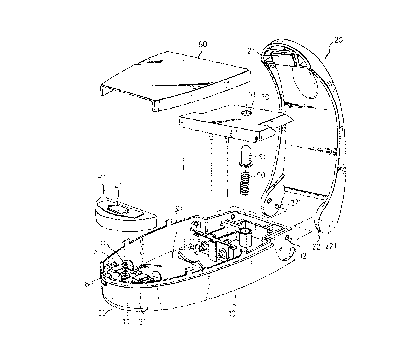
A hand-held electric heat sealing apparatus including a casing, a heat sealing unit and a press handle, wherein a safety switch is mounted in the casing and shifted to stop metal contact plates of the heat sealing unit from contacting the two terminals of a power supply circuit in the casing; the heat sealing unit includes a hat insulative base having a projecting block, an electric heating wire fastened to the projecting block and connected to opposite metal contact plates of the heat sealing unit, a cover shell covered on the casing over the heat insulative base and having a center opening through which the projecting block of the heat insulative base projects out of the cover shell, a heat insulative sheet covered over the electric heating wire, and a cover frame fastened to the cover shell to hold the heat insulative sheet in place; the casing has a rear chamber, an electric socket in the rear chamber for receiving an electric plug, and an upright stop rod disposed in the rear chamber adapted for holding the electric wire of the electric plug in place.


French Abstract

Un appareil manuel de thermoscellage électrique comprenant un boîtier, un dispositif de thermoscellage, et une poignée de pression, dans lequel un interrupteur de sécurité, monté sur le boîtier, est déplacé pour empêcher tout contact entre les plaques de contact métalliques de l'appareil de thermoscellage et les deux bornes d'un circuit d'alimentation électrique dans le boîtier ; l'appareil de thermoscellage comprend un socle d'isolation thermique avec un bloc saillant, un conducteur de chauffage électrique fixé sur le bloc saillant et raccordé à des plaques de contact métalliques opposées de l'appareil de thermoscellage, une coquille d'habillage couverte sur le boîtier, au-dessus du socle d'isolation thermique, et possédant une ouverture centrale par laquelle le bloc saillant du socle d'isolation thermique fait saillie de la coquille d'habillage, une feuille d'isolation thermique couverte sur le conducteur de chauffage électrique, et un cadre d'habillage fixé sur la coquille d'habillage de façon à maintenir la feuille d'isolation thermique en place ; le boîtier possède une chambre postérieure, une prise électrique dans la chambre postérieure, dans laquelle se place une fiche électrique, et une tige de butée placée dans la chambre postérieure adaptée pour tenir le conducteur électrique de la fiche électrique en place.

Claims

Note: Claims are shown in the official language in which they were submitted.


CLAIMS:
1. A hand-held electric heat sealing apparatus
comprising a casing having a front end and a rear end, a
compression spring mounted in the front end of said casing, a
power supply circuit having a pair of metal contact plates
mounted inside said casing and connected to two opposite
terminals of a power source, a heat sealing unit mounted in the
front end of said casing and supported on said compression
spring and moved vertically relative to said casing, a press
handle having a rear end pivoted to the rear end of the casing
and a front end mounted with a heat insulative pad adapted to
press an object against said heat sealing unit for permitting
it to be sealed, said heat sealing unit comprising a heat
insulative base having a projecting block raised from said heat
insulative base in the middle, an electric heating wire
fastened to said heat insulative base, and two metal contact
plates disposed at two opposite sides of said heat insulative
base and connected to two opposite ends of said electric
heating wire and adapted for connecting to the two metal
contact plates of said power supply circuit, wherein: said heat
sealing unit comprises a cover shell covered on the front end
of said casing over said heat insulative base and having a
center opening through which the projecting block of said heat
insulative base projects out of said cover shell, a heat
insulative sheet supported on said cover shell over its center
opening and disposed in contact with the electric heating wire
of said heat sealing unit, and a cover frame fastened to said
cover shell to hold said heat insulative sheet in place.
2. The hand-held electric heat sealing apparatus of
claim 1, wherein said heat insulative sheet is preferably made
from a meshed metal sheet coated with Teflon.
8

3. The hand-held electric heat sealing apparatus of
claim 1, wherein said cover shell of said heat sealing unit has
two insertion holes spaced from two opposite sides of its
center opening, and the cover frame of said heat sealing unit
has two downward plug strips at two opposite ends respectively
plugged into the insertion slots of said cover shell.
4. The hand-held heat sealing apparatus of claim 1,
wherein the cover frame of said heat sealing unit has a center
opening corresponding to the center opening of said cover shell
through which a part of said heat insulative sheet and the
projecting block of said heat insulative base can be forced out
of the cover frame of said heat sealing unit.
5. The hand-held electric heat sealing apparatus of
claim 1, wherein the projecting block of said heat insulative
base of said heat sealing unit has a smoothly arched cross
section.
6. A hand-held electric heat sealing apparatus
comprising a casing having a front end and a rear end, a
compression spring mounted in the front end of said casing, a
power supply circuit having a pair of metal contact plates
mounted inside said casing and connected to two opposite
terminals of a power source, a heat sealing unit mounted in the
front end of said casing and supported on said compression
spring and moved vertically relative to said casing, a press
handle having a rear end pivoted to the rear end of the casing
and a front end mounted with a heat insulative pad adapted to
press an object against said heat sealing unit for permitting
it to be sealed, said heat sealing unit comprising a heat
insulative base having a projecting block raised from said heat
insulative base in the middle, an electric heating wire
fastened to said heat insulative base, and two metal contact
plates disposed at two opposite sides of said heat insulative
base and connected to two opposite ends of said electric
9

heating wire and adapted for connecting to the two metal
contact plates of said power supply circuit, wherein a safety
switch is mounted in the front end of said casing, and
comprised of a switch lever extended out of said casing, and an
electrically insulative bumper connected to said switch lever,
said electrically insulative bumper being moved by said switch
lever between a first position in which said electrically
insulative bumper is stopped above the metal contact plates of
said power supply circuit to prohibit contact of the metal
contact plates of said heat sealing unit from the metal contact
plates of said power supply circuit, and a second position in
which said electrically insulative bumper is moved away from
the metal contact plates of said power supply circuit for
permitting the metal contact plates of said heat sealing unit
to be forced into contact with the metal contact plates of said
power supply circuit.
7. The hand-held electric heat sealing apparatus of
claim 6, wherein said switch lever and said electrically
insulative bumper are integrally molded from plastic and
mounted on a revolving shaft in a hole at the front end of said
casing.
8. The hand-held electric heat sealing apparatus of
claim 7, wherein said electrically insulative bumper has a
B-shaped profile.
9. The hand-held electric heat sealing apparatus of
claim 6, wherein said casing has a bottom chamber and a pivoted
safety cutter means moved in and out of said bottom chamber,
said safety cutter means comprising a cutter holder having at
least one notch at one side and a cutter blade fastened to said
cutter holder within said at least one notch.
10. A hand-held electric heat sealing apparatus
comprising a casing, a heat sealing unit, and a press handle
10

pivoted to said casing and forced to act against said heat
sealing unit, said casing comprising a top chamber, and a top
cover plate covered on said top chamber, wherein said top
chamber comprises two upright side walls at two opposite sides,
a rigid member mounted on the inside and stopped between said
upright side walls, and a plurality of hooks raised from said
upright from said upright side walls, said top cover plate
having two downward mounting flanges respectively forced into
engagement with the hooks of the upright side walls of said top
chamber.
11. The hand-held electric heat sealing apparatus of
claim 10, wherein said rigid member is a metal case.
12. The hand-held electric heat sealing apparatus of
claim 10, wherein said casing comprises a rear chamber at one
end, an electric plug adapted for receiving an electric plug
for transmitting electricity to said heat sealing unit, an
upright stop rod disposed inside said rear chamber and spaced
from said electric socket at one side and adapted for holding
the electric wire of the electric plug which is connected to
said electric socket.
13. The hand-held electric heat sealing apparatus of
claim 10, wherein said upright stop rod is disposed at an
entrance of said rear chamber and defining with an inside wall
of said casing a retaining hole for holding the electric wire
of the electric plug which is connected to said electric
socket.
11

Description

Note: Descriptions are shown in the official language in which they were submitted.


CA 02213829 2000-O1-26
76302-14
HAND-HELD ELECTRIC HEAT SEALING APPARATUS
BACKGROUND OF THE INVENTION
The present invention relates to electric heat
sealing apparatus, and more particularly to an improved
structure of hand-held electric heat sealing apparatus.
Various hand-held heat sealing apparatus have been
disclosed, and have appeared on the market. US Pat. No.
5,142,123 discloses an example of conventional hand-held heat
sealing apparatus. The conventional hand-held heat sealing
apparatus are functional, however they are not safe in use.
SL1N~1ARY OF THE INVENTION
According to one aspect of the present invention, the
hand-held heat sealing apparatus comprises a casing, a heat
sealing unit mounted in the casing and supported on a
compression spring, a press handle pivoted to the casing and
acted against the heat sealing unit, and a safety switch
mounted in the casing and shifted to stop metal contact plates
of the heat sealing unit from contacting the two terminals of a
power supply circuit in the casing. According to another
aspect of the present invention, the hand-held electric heat
sealing apparatus can be an AC type hand-held electric heat
sealing apparatus, a DC type hand-held electric heat sealing
apparatus, or a AC/DC dual usage type hand-held electric heat
sealing apparatus. According to still another aspect of the
present invention, the heat sealing unit comprises a hat
insulative base having a projecting block, and electric heating
wire fastened to the projecting block and connected to opposite
metal contact plates of the heat sealing unit, a cover shell
covered on the casing over the heat insulative base and having
a center opening through which the projecting block of the heat
insulative base projects out of the cover shell, a heat
1

CA 02213829 2000-O1-26
76302-14
insulative sheet covered over the electric heating wire, and a
detachable cover frame fastened to the cover shell to hold the
heat insulative sheet in place. Because the cover frame is
detachable, the heat insulative sheet can be conveniently
replaced. According to still
la

CA 02213829 1997-08-25
another aspect of the present invention, the casing comprises
a top chamber, and a top cover plate covered on the top chamber,
wherein the top chamber comprises two upright side walls at
two opposite sides, a rigid member for example a metal case
mounted on the inside and stopped between the upright side
walls, and a plurality of hooks raised from the upright side
walls, the top cover plate having two downward mounting
flanges respectively forced into engagement with the hooks
of the upright side walls of the top chamber. According to
still another aspect of the present invention, when the
casing has a rear chamber, an electric socket in the rear
chamber for receiving an electric plug, and an upright stop
rod disposed in the rear chamber adapted for holding the
electric wire of the electric plug in place.
BRIEF DESCRIPTION OF THE DRAWINGS
Fig. l.is an exploded view of a handy electric heat
sealing apparatus according to one embodiment of the present
invention;
Fig. 2 is an exploded view of the heat sealing unit
of the handy electric heat sealing apparatus shown in Figure
1;
Fig. 3 is an elevational view of an alternate form
of the heat insulative base for the heat sealing unit
according to the present invention;
Fig. 4 shows the safety switch disconnected from the
casing according to the present invention;
Fig. 5 is a top view of a part of the present invention,
showing the safety switch installed and turned;
Fig. 6 is an elevational view of a part of the present
invention, showing the safety cutter holder moved out of the
bottom chamber of the casing;
Fig. 7 is an exploded view of an alternate form of
the present invention;
Fig. 8 is an oblique rear elevation of the present
invention;
Fig. 9 shows the rear cover removed from the rear
chamber of the casing according to the present invention;

CA 02213829 1997-08-25
and
Fig. 10 shows the relationship between the electric
socket and upright stop rod of the casing and the electric
plug according to the present invention.
DETAILED DESCRIPTION OF THE PREFERRED EMBODIMENT
Referring to Figure 1, a handy electric heat sealing
apparatus comprises a casing 10 defining a chamber 30 adapted
for holding a battery set . A pairs of metal contact plates
31 are mounted inside the casing 10, and respectively
connected to the two opposite terminals of the battery set
mounted in the chamber 30. A cylindrical upright support
11 is disposed inside the casing 10 near its front end. A
compression spring 111 is mounted on the upright support 11.
A heat sealing unit 40 is supported on the compression spring
111, and moved vertically relative to the casing 10.
Referring to Figure 2, the heat sealing unit 40
comprises a heat insulative base 41, an electric heating wire
42, a pair of metal contact plates 43, a cover shell 44, a
heat insulative sheet 45, and a cover frame 46. The heat
insulative base 41 comprises a proj ecting block 411 raised
from its top side in the middle . The electric heating wire
42 is fastened to the projecting block 411 of the heat
insulative base 41. The metal contact plates 43 are
respectively fastened to two opposite sides of the heat
insulative base 41 to hold down the electric heating wire
42. The cover shell 44 covered on a front part of the casing
10 over the heat insulative base 41, having a center opening
441 through which the projecting block 411 ,of the heat
insulative base 41 projects out of the cover shell 44, and
two insertion slots 442 equally spaced from the center
opening 441 at two opposite sides . The heat insulative sheet
45 is covered on the projecting block 411 of the heat
insulative base 41 over the electric heating wire 42, and

CA 02213829 1997-08-25
disposed outside the cover shell 44. The cover frame 46 is
covered on the cover shell 44 to hold the heat insulative
sheet 45 in place . The cover frame 46 comprises two downward
plug strips 462 at two opposite ends respectively plugged
into the insertion slots 442 of the cover shell 44, and a
center opening 461 corresponding to the center opening 441
of the cover shell 44. The heat insulative sheet 45 is
preferably made from a meshed metal sheet coated with Teflon
that protects the electric heating wire 42 and provides a
smooth contact surface.
Referring to Figure 1 again, a press handle 20 is
pivoted to one end, namely, the rear end of the casing 10
remote from the heat sealing unit 40. The press handle 20
comprises a heat insulative pad 21 transversely disposed at
one end, and a pair of lugs 22 longitudinally and bilaterally
disposed at an opposite end. The lugs 22 have a respective
stub pivot pin 221 at an inner side respectively mounted in
a respective pivot hole 12 at the rear end of the casing 10.
Further, a spring 50 is mounted inside the casing 10 near
its rear end and covered with a spring cap 51. The spring
50 imparts an upward pressure to the press handle 20, causing
the press handle 20 to be supported in a lifted position in
which the heat insulative pad 21 is spaced from the heat
insulative sheet 45 of the heat sealing unit 40 at a distance.
A rear cover plate 70 is covered on the rear end of the casing
10, having a through hole 71 through which the spring cap
51 projects out of the rear cover plate 70. An intermediate
cover plate 60 is covered on the middle part of the casing
10 between the heat sealing unit 40 and the rear cover plate
70.
Referring to Figure 3 and Figure 2 again, the
proj ecting block 411 of the heat insulative base 41 may be
variously shaped. For example, the projecting block 411

CA 02213829 1997-08-25
shown in Figure 2 has a rectangular profile; the projecting
block 411 shown in Figure 3 has a smoothly arched cross
section.
Referring to Figures 1 and 2 again, when the press
handle 20 is depressed, the heat sealing unit 40 is lowered,
and the metal contact plates 43 of the heat sealing unit 40
are respectively forced into contact with the metal contact
plates 31 in the casing 10, thereby causing electricity to
be connected to the electric heating wire 42 . After sealing,
the press handle 20 is released, and the heat sealing unit
40 is pushed upwards by the compression spring 111 to
disconnect its metal contact plates 43 from the metal contact
plates 31 in the casing 10, and therefore electricity is cut
of f .
Referring to Figure 4 and Figure 1 again, a safety
switch 80 is mounted in the front end of the casing 10. The
safety switch 80 comprises a switch 81, an electrically
insulative bumper 82, and a shaft 83. The shaft 83 is
inserted into a hole 13 inside the casing 10 at its front
end. The switch lever 81 extends out of a front notch 14
of the casing 10. The electrically insulative bumper 82 has
a V-shaped profile.
Referring to Figure 5, when the handy electric heat
sealing apparatus is not in use, the switch lever 81 is shifted
to the off position force the electrically insulative bumper
82 into contact with the metal contact plates 31 at the top,
and therefore the metal contact plates 43 of the heat sealing
unit 40 are prohibited from touching the metal contact plates
31 in the casing 10. When to use the handy electric heat
sealing apparatus, the switch lever 81 is shifted to the on
position to move the electrically insulative bumper 82 away
from the metal contact plates 31 in the casing 10, allowing
the metal contact plates 43 of the heat sealing unit 40 to
be forced into contact with the metal contact plates 31 in

CA 02213829 1997-08-25
the casing 10 to close the circuit.
Referring to Figure 6 and Figure 1 again, the casing
further comprises a bottom opening 15. A swivel cutter
holder 90 is pivoted to the casing 10. The swivel cutter
5 holder 90 can be turned inwards and received in the bottom
opening 15 of the casing 10 ( see Figure 1 ) , or turned outwards
and extended out of the bottom opening 15 of the casing 10
(see Figure 6). The swivel cutter holder 90 comprises two
notches 91, and a cutter blade 92 fastened to the notches
10 91. Because the cutter blade 92 is mounted within the notches
91, it does not cut the user's fingers when the user turns
the cutter holder 90 with the hand.
Figure 7 shows an alternate form of the present
invention. This alternate form consumes AC power supply.
According to this alternate form, the chamber 30 of tre casing
10 comprises two upright side walls 16 and a plurality of
hooks 17 respectively raised from the upright side walls 16;
a metal case 100 is mounted within the chamber 30 of the casing
10 and retained between the vertical side walls 16; the
intermediate cover plate 60 is covered over the metal case
100, having two downward mounting flanges 61 at two opposite
sides respectively forced into engagement with the hooks 17 .
The metal case 100 increases the weight of the handy electric
heat sealing apparatus, and simultaneously imparts an
outward pressure to the upright side walls 16 of the chamber
to force the hooks 17 into engagement with the downward
mounting flanges 61 of the intermediate cover plate 60.
Referring to Figures from 8 to 10, the casing 10
comprises a rear chamber 111, a rear cover 110 covered on
30 the rear chamber 111, an electric socket 112 disposed in the
rear chamber 111, an upright stop rod 114 disposed at the
entrance 113 of the rear chamber 111, and a retaining hole
115 at the entrance 113 of the rear chamber 111. When the
6

CA 02213829 1997-08-25
rear cover 110 is removed from the rear chamber 111 of the
casing 10, an electric plug 120 can be connected to the
electric socket 112 to transmit electric power to the heat
sealing unit of the handy electric heat sealing apparatus,
S and the electric wire 121 of the electric plug 120 can be
inserted through the retaining hole 115 and extended out of
the rear chamber 111 of the casing 10.
It is to be understood that the drawings are designed
for purposes of illustration only, and are not intended as
a definition of the limits and scope of the invention
disclosed.

Representative Drawing
A single figure which represents the drawing illustrating the invention.
Administrative Status

2024-08-01:As part of the Next Generation Patents (NGP) transition, the Canadian Patents Database (CPD) now contains a more detailed Event History, which replicates the Event Log of our new back-office solution.

Please note that "Inactive:" events refers to events no longer in use in our new back-office solution.

For a clearer understanding of the status of the application/patent presented on this page, the site Disclaimer , as well as the definitions for Patent , Event History , Maintenance Fee  and Payment History  should be consulted.

Event History

Description Date
Inactive: Expired (new Act pat) 2017-08-25
Letter Sent 2007-10-22
Inactive: Office letter 2007-09-25
Inactive: IPC from MCD 2006-03-12
Inactive: Entity size changed 2002-04-30
Grant by Issuance 2000-07-18
Inactive: Cover page published 2000-07-17
Pre-grant 2000-04-18
Inactive: Final fee received 2000-04-18
Notice of Allowance is Issued 2000-03-08
Letter Sent 2000-03-08
Inactive: Approved for allowance (AFA) 2000-02-21
Amendment Received - Voluntary Amendment 2000-01-26
Inactive: S.30(2) Rules - Examiner requisition 1999-09-22
Application Published (Open to Public Inspection) 1999-02-25
Inactive: IPC assigned 1997-11-12
Classification Modified 1997-11-12
Inactive: First IPC assigned 1997-11-12
Inactive: Filing certificate - RFE (English) 1997-10-30
Filing Requirements Determined Compliant 1997-10-30
Application Received - Regular National 1997-10-28
All Requirements for Examination Determined Compliant 1997-08-25
Request for Examination Requirements Determined Compliant 1997-08-25

Abandonment History

There is no abandonment history.

Maintenance Fee

The last payment was received on 1999-05-13

Note : If the full payment has not been received on or before the date indicated, a further fee may be required which may be one of the following

  • the reinstatement fee;
  • the late payment fee; or
  • additional fee to reverse deemed expiry.

Please refer to the CIPO Patent Fees web page to see all current fee amounts.

Owners on Record

Note: Records showing the ownership history in alphabetical order.

Current Owners on Record
AMMY CHOU
Past Owners on Record
None
Past Owners that do not appear in the "Owners on Record" listing will appear in other documentation within the application.
Documents

To view selected files, please enter reCAPTCHA code :


To view images, click a link in the Document Description column. To download the documents, select one or more checkboxes in the first column and then click the "Download Selected in PDF format (Zip Archive)" or the "Download Selected as Single PDF" button.

List of published and non-published patent-specific documents on the CPD .

If you have any difficulty accessing content, you can call the Client Service Centre at 1-866-997-1936 or send them an e-mail at CIPO Client Service Centre.


Document
Description 
Date
(yyyy-mm-dd) 
Number of pages   Size of Image (KB) 
Abstract 2000-01-26 1 31
Description 2000-01-26 8 309
Claims 2000-01-26 4 184
Description 1997-08-25 7 306
Abstract 1997-08-25 1 30
Claims 1997-08-25 4 181
Drawings 1997-08-25 8 161
Cover Page 2000-06-28 1 49
Cover Page 1999-03-10 2 77
Representative drawing 1999-03-10 1 18
Representative drawing 2000-06-28 1 18
Filing Certificate (English) 1997-10-30 1 164
Reminder of maintenance fee due 1999-04-27 1 111
Commissioner's Notice - Application Found Allowable 2000-03-08 1 166
Correspondence 2000-04-18 2 58
Fees 1999-05-13 1 40
Correspondence 2007-09-25 1 18
Correspondence 2007-10-22 1 14
Correspondence 2007-10-04 2 50