Note: Descriptions are shown in the official language in which they were submitted.
CA 02214121 1997-08-28
WO 96/29620 PCT/US96/01897
RE~'ROREFLECTIVE AP~LIQUE
This invention pertains to a retroreflective applique that can be furnished to
a
garment assembler without a carrier and without a release liner.
Retroreflective appliques have the ability to return a substantial portion of
incident light back towards the light source. This unique ability has promoted
widespread use of retroreflective appliques on clothing. Persons who work or
exercise
near motor vehicle traffic need to be conspicuously visible so that they do
not get
struck by passing motor vehicles. When placed on clothing, the retroreflective
appliques highlight a person's presence by retroreflecting light from motor
vehicle
headlamps.
A retroreflective applique typically comprises an optical lens element layer,
a
polymeric binder layer, and a reflective layer. The optical lens elements
commonly are
microspheres that are partially embedded in the polymeric binder layer. The
reflective
layer typically comprises aluminum, silver, or a dielectric mirror that
usually is
disposed on the embedded portions of the microspheres. Light striking the
front
surface of the retroreflective applique passes through the microspheres and is
reflected
by the reflective layer to re-enter the microspheres where the light's
direction is then
altered to travel back towards the light source.
Retroreflective appliques have been made by partially embedding a microsphere
layer in a thermoplastic carrier web, applying a reflective material over the
microspheres' protruding portions, and then forming a binder layer over the
coated
microspheres. Often a pressure-sensitive adhesive is applied on the binder
layer's back
surface, and a release liner is placed over the adhesive until the applique is
secured to a
substrate. The completed applique (also referred to as a transfer sheet) is
supplied to a
garment assembler in this form, and the garment assembler secures the applique
to an
article of clothing by removing the release liner and adhering the applique to
an outer
s surface of the article of clothing. The carrier is then separated from the
applique to
expose the microspheres so that the applique can retroreflect light. Although
known
-1-
CA 02214121 1997-08-28
WO 96/29620 PCTlUS96/01897
retroreflective appliques demonstrate very good retroreflective performance
and are
very effective in highlighting a wearer's presence when light strikes the
clothing at
nighttime, the known appliques possess some drawbacks.
A first drawback is that the applique requires use of a carrier web that
becomes
discarded as waste by the garment assembler. The carrier web is not separated
from
the applique before the manufacturer supplies the applique to the garment
assembler
because the applique is not yet secured to a substrate. If the applique was
separated
from the carrier beforehand, the applique's binder layer and the reflective
layer can
become irreversibly stretched when the carrier is pulled away from the
applique. This
irreversible stretching can harm the applique's retroreflective performance.
A second drawback is that when the applique is secured to the substrate with
heat, residual carrier web material can remain on the exposed surface of the
microspheres, causing a reduction in retroreflective performance. Also, the
thermoplastic earner limits the quantity of heat that can be applied to the
applique
because, if too much heat is applied to the carrier, the carrier can stick to
the
microspheres and can become very di~cult to remove. Limiting the heat supplied
to
the applique can cause a poor bond between the applique and the substrate.
Another drawback is that .known transfer sheets are supplied to the garment
assembler with a release liner that, like the carrier web, also becomes
discarded as
waste. Of course, it is not beneficial from an economic or environmental
standpoint to
discard the release liner or the carrier web as waste.
The present invention provides a retroreflective applique that can be supplied
to a garment assembler or others without a carrier web and without a release
liner.
The carrier web can be separated from the microspheres before the applique is
secured
to a substrate, allowing the carrier web to be recycled by the manufacturer
and
allowing more heat to be applied when heat laminating the applique to a
substrate.
The applique also eliminates the need for a release liner and therefore
further reduces
waste.
In brief summary, the retroreflective applique of the invention comprises:
-2-
CA 02214121 2006-08-30
60557-5588
(a) a supporting structure having first and second
major surfaces and containing a non-filamentary layer of an
acrylic polymer, the second major surface being capable of
acting as a heat-activatable adhesive;
(b) a layer of optical lens elements having a
first portion protruding from the first major surface of the
supporting structure and having a second portion embedded in
the layer of the acrylic polymer; and
(c) a reflective material disposed behind the
second portion of the layer of optical lens element=s.
The present invention also provides a met=hod of
making a retroreflective applique, which comprises the steps
of
(a) supporting a first portion of a layer of
optical lens elements in a carrier web such that a second
portion of the layer of optical lens elements protrudes from
the carrier web;
(b) applying a coating of a reflective material on
the second portion of the layer of optical lens elements;
(c) forming over the second portion of the optical
lens elements after the reflective material has been applied
a supporting structure that includes a non-filamentary
acrylic polymer layer, the supporting structure being
capable of acting as a heat activatable adhesive and the
second portion of the optical lens elements being embedded
in the acrylic polymer layer; and
(d) separating the carrier web from the supporting
- 3 -
CA 02214121 2006-08-30
60557-5588
structure to expose the first portion of the optical lens
elements to produce the self-supported exposed lens
retroreflective applique, the separation occurring before
the retroreflective applique's supporting structure is
secured to a substrate.
According to one aspect of the present invention,
there is provided an exposed lens retroreflective applique
that comprises: (a) a supporting structure having first and
second major surfaces and containing a non-filameni=ary layer
of a self-crosslinked acrylic polymer, the second major
surface being capable of acting as a heat-activatable
adhesive; (b) a layer of optical lens elements having a
first portion protruding from the first major surface of the
supporting structure and having a second portion embedded in
the layer of the self-crosslinked acrylic polymer; and
(c) a reflective material disposed behind the second portion
of the layer of optical lens elements.
According to another aspect of the present
invention, there is provided a method of making a self-
supporting exposed lens retroreflective applique, which
method consists essentially of: (a) supporting a first
portion of a layer of optical lens elements in a carrier web
such that a second portion of the layer of optical lens
elements protrudes from the carrier web; (b) applying a
coating of a reflective material on the second portion of
the layer of optical lens elements; (c) forming over the
second portion of the optical lens elements after the
reflective material has been applied a supporting structure
that has first and second major surfaces and that includes a
non-filamentary self-crosslinked acrylic polymer layer, the
- 3a -
CA 02214121 2006-08-30
60557-5588
second portion of the optical lens elements being embedded
in the crosslinked acrylic polymer layer and the second
major surface of the supporting structure being capable of
acting as a heat-activatable adhesive; and (d) separating
the carrier web from the supporting structure to expose the
first portion of the optical lens element to produce the
self-supported exposed lens retroreflective applique, the
separation occurring before the retroreflective applique's
supporting structure is secured to a substrate.
The applique of the invention differs from known
appliques in that the optical lens elements are supported by
a polymeric supporting structure that contains a non-
filamentary acrylic polymer layer and that is capable of
acting as a heat-activatable adhesive. The use of such a
supporting structure enables the carrier web to be separated
from the polymeric supporting structure before the applique
is permanently secured to a substrate. This separation step
can be accomplished without causing
- 3b -
CA 02214121 1997-08-28
WO 96/29620 PCT/US96/01897
substantial damage to the retroreflective performance of the applique. The
ability to
separate the carrier web from the applique before the latter is secured to a
substrate
also is beneficial because it allows greater temperatures to be used in
securing the
applique to a substrate. higher temperatures allow a stronger bond to be
achieved
between the applique and the substrate. Known carriers are thermoplastic and
thus
preclude use of higher temperatures because such temperatures cause the
carrier
material to stick to the microspheres. The carrier web can be retained by the
manufacturer for recycle, as opposed to being supplied to a garment assembler
and
subsequently discarded as waste. Further, a release liner is not needed in the
present
invention because the applique can be heat-activatably applied rather than
being
applied through use of a pressure-sensitive adhesive. Thus, neither the
carrier web nor
the release liner become discarded by the garment assembler, making the
applique and
method of the invention more favorable from economic and environmental
standpoints.
In addition, the overall weight and volume of the applique is less, thereby
reducing
shipping and storage costs.
These and other advantages of the invention are more fully shown and
described in the drawings and detailed description of this invention, where
like
reference numerals are used to represent similar parts. It is to be
understood,
however, that the drawings and description are for the purposes of
illustration only and
should not be read in a manner that would unduly limit the scope of this
invention.
In the drawings:
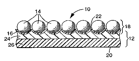
FIG. 1 is a cross-section of a retroreflective applique 10 in accordance with
the
present invention;
FIG. 2 schematically illustrates a method of manufacturing a retroreflective
applique 10 in accordance with the present invention; and
FIG. 3. is a front view of an article of clothing 60 bearing a retroreflective
applique 10 in accordance with the present invention.
The drawings are idealized and are not drawn to scale.
In the practice of the present invention, an exposed lens retroreflective
applique
is provided that can have the earner web removed from the applique before it
is
-4-
CA 02214121 1997-08-28
WO 96/29620 PCT/US96/01897
secured to a substrate. F'iG. 1 illustrates a portion of a retroreflective
applique 10 of
the invention. Retroreflective applique 10 includes a supporting structure 12,
optical
lens elements that may be a monolayer of microspheres 14, and a reflective
material 16.
Together the microspheres 14 and the reflective material 16 form a
retroreflective
portion 18 capable of returning a substantial quantity of incident light
towards the light
source. The supporting structure 12 has a first or rear surface 20 and a
second or front
surface 22. As shown, the supporting structure 12 contains two polymeric
layers 24
and 26. Polymeric layer 24 typically is referred to as a "binder layer" and
comprises a
non-filamentary acrylic polymer, and layer 26 may comprise a polymers) capable
of
acting as a heat-activatable adhesive. "Non-filamentary" means the layer does
not
consist essentially of filaments; see contrawise, U.S. Patent 5,128,804. The
term
"acrylic polymer" means a thermoplastic or thermoset polymer or copolymer made
from acrylic acid, methacrylic acid, itaconic acid, citraconic acid, malefic
acid, fumaric
acid, esters of these acids, acrylonitrile, or combinations thereof.
Preferably, layer 26
comprises an acrylic polymer made from acrylic acid, methacrylic acid, ethyl
acrylate,
butyl acrylate, ethyl hexyl acrylate, or combinations thereof.
Polymeric layer 26 by itself or in conjunction with layer 24 allows polymeric
supporting structure 12 to act as a heat-activatable adhesive on rear surface
20. As the
term is used herein, "heat activatable adhesive" means an adhesive that can be
activated
by heating to more than about 50°C, allowing the applique to be bonded
to a substrate
by the application of pressure, where the applique and the substrate are not
otherwise
able to be bonded to each other at room temperature. Preferably, the adhesive
is not
activated until it is heated to at least 75 °C.
The layer of microspheres 14 has a first portion that protrudes from the
supporting structure 12 so as to be exposed to the ambient environment. In
retroreflective appliques, like the present invention, where the microspheres
are
exposed to the ambient environment -- that is, they are not enclosed or
encapsulated,
by for example, a polymeric cover film -- are referred to as "an exposed lens
retroreflective applique." The layer of microspheres 14 has a second portion
-5-
CA 02214121 1998-10-26
embedded in the front surface 22 of polymeric suppbrting
structure 12. Reflective material 16 is located behind the
embedded portion of the layer of microspheres and preferably
is disposed thereon.
The supporting structure contains one or more non-
filamentary continuous polymeric layers, which together
preferably have a thickness of about 25 to about 250
micrometers. By ~~continuous~~ is meant the polymeric layer
does not possess any voids or openings that would render the
l0 polymeric supporting structure fluid permeable. Preferably,
the supporting structure has a thickness of about 50 to 75
micrometers. Thicknesses less than 25 micrometers may be too
thin to adhere to both a substrate and the optical elements,
and thicknesses greater than 250 micrometers may unnecessarily
stiffen the applique and add to its cost.
Layers 24 and 26 together or independently provide
structure 12 and ultimately retroreflective applique 10 with a
tensile strength preferably greater than 3.5 x 10⁶ N/m2. More
preferably, the retroreflective applique has a tensile
20 strength greater than 6 x 10⁶ N/m2, and still more preferably
is greater than 10 x 106 N/m2. At the upper end, the tensile
strength may be as high as 50 x 106 N/m2 but typically is less
than 40 x 106 N/m2. Binder layer 24 can be a self-
crosslinking acrylic polymer such as HA-8TM available from
Rohm and Haas, Philadelphia, Pennsylvania. As the term is
used herein, ~~self-crosslinking~~ means the polymer is capable
of cross-linking to produce a higher molecular weight polymer
without use of e-beam radiation or a crosslinking agent
- 6 -
60557-5588
CA 02214121 1998-10-26
separate from the initial polymer. Polymeric layer 26 may be
a thermoplastic polymer such as a copolymer of ethylene and
acrylic acid, for example, PrimacorTM 3440 available from Dow
Chemical Company, Midland, Michigan. Dow Corning z-6040
adhesion promoter (available from Dow Corning, Midland,
Michigan) may be used with HA-8TM to provide superior dry-
cleaning and home laundering durability. Polymeric layer 26
typically is about 10 to 150 micrometers thick.
The binder layer of the supporting structure also
l0 may contain one or more additives such as colorants (for
example, pigments, dyes, metal flakes), fillers, stabilizers
(for example, thermal stabilizers and antioxidants such as
hindered phenols and light stabilizers such as hindered amines
or ultraviolet stabilizers), flame retardants,
- 6a -
60557-5588
CA 02214121 1997-08-28
WO 96/29620 PCTIUS96/01897
flow modifiers (for example, surfactants such as fluoropolymer silicones),
plasticizers,
elastomers, and coupling agents. Care should be taken when selecting such
additives
because some can detrimentally affect laundering durability of the
retroreflective
applique. Because the appliques are commonly used on clothing, laundering
durability
is an important consideration; see, for example, U.S. Patents 5,200,262 and
5,283,101.
It has been found that use of a substantial amount of some pigments, for
example,
titanium dioxide, can adversely affect post-wash retroreflectivity. Other
additives,
however, may improve laundering durability. For example, silane coupling
agents such
as Dow Corning Z 6040 may be added to the binder layer at about 1 to 15 parts
by
weight (dry). Elastomers -- such as Hypalon~ 20 S (available from E.I. Dupont
de
Nemours and Company, Wilmington, Delaware), Polysar'~ EPM 306 P (available
from Miles, Inc., Polysar Rubber Division, Akron, Ohio), and Nipol~ VT 4555
(available from Zeon Chemicals, Rolling Meadows, Ilfinois) -- may improve
laundering
durability when the binder layer is an ethylene/acrylic acid copolymer.
Preferably, the
additives are resistant to degradation or leaching out of the polymeric
supporting
structure during laundering.
The supporting structure's binder layer optionally may be formulated with a
colorant selected to blend with or match the color of the reflective material
to mask
any loss of optical lens elements which may result from scratching the front
surface of
applique against furniture, walls, or any other object or surface. When an
optical lens
element becomes displaced from the applique, a portion of the reflective
material
directly beneath the lens element usually also is removed from the sheeting.
If the
reflective material is not transparent and it does not match the color of the
underlying
binder layer, the loss of the optical lens element becomes noticeable.
The term "optical lens elements" means discrete elements capable of altering
the direction of light so that, in conjunction with the reflective material, a
substantial
quantity of incident light can be retroreflected. As indicated above, the
optical lens
elements used in retroreflective appliques of this invention can be
microspheres that,
preferably, are substantially spherical in shape in order to provide the most
uniform and
eflzcient retroreflection. The microspheres preferably also are substantially
transparent
CA 02214121 2006-08-30
60557-5588
so as to minimize absorption of light so that a large percentage of the
incident light is
retroreflected. As the term is used herein, "transparent" means capable of
transmitting
Light. Preferably, the optical lens elements transmit at least 80 percent of
the intensity
of incident light in the visible spectrum (about 400 to 700 manometers (nm)
S wavelength). More preferably, the microspheres are capable of transmitting
at least 90
percent of the intensity of light in the visible spectrum. The microspheres
often are
substantially colorless but may be tinted or colored in some other fashion.
The microspheres may be made from glass, a non-vitreous ceramic
composition, or a synthetic resin. Glass and ceramic microspheres are
preferred
because they tend to be harder and more durable than microspheres made from
synthetic resins. Examples of microspheres that may be used in this invention
are
disclosed in the following United States patents: 1,175,224, 2,461,01 l,
2,726,161,
2,842,446, 2,853,393, 2,870,030, 2,939,797, 2,965,921, 2,992,122, 3,468,681,
3,946,130, 4,192,576, 4,367,919, 4,564,556, 4,758,469, 4,?72,511, and
4,931,414.
The microspheres typically have an average diameter in the range of about 30
to 200 micrometers. Microspheres smaller than this range tend to provide lower
levels
of retroreflection, and microspheres larger than this range may impart an
undesirably
rough texture . to the applique or may undesirably reduce its flexibility. The
microspheres typically have a refractive index of about 1.7 to about 2.0, the
range
typically considered to be useful in exposed lens retroreflective products.
The reflective material can be a layer comprising an elemental metal that
preferably is capable of specularly reflecting light. A variety of metals may
be used to
provide a specular reflective metal layer. These include aluminum, silver,
chromium,
gold, nickel, magnesium, and the like, in elemental form, and combinations
thereof.
Aluminum and silver are the preferred metals for use in a reflective layer
from a
performance standpoint. The metal may be a continuous coating such as is
produced
by vacuum-deposition, vapor coating, chemical-deposition, or electroless
plating. It is
to be understood that in the case of aluminum, some of the metal may be in the
form of
the metal oxide and/or hydroxide. Aluminum and silver metals are preferred
because
_g_
CA 02214121 2006-08-30
60557-5588
they tend to provide the highest retroreSective brightness. The metal layer
should be
thick enough to reflect incoming light. Typically, the reflective metal layer
is about SO
to 1 SO manometers thick. Although the reflective color of a silver coating
can be
brighter than an aluminum coating, an aluminum layer nornially is more
preferred
because it can provide better laundering durability when adhered to a glass
optical
element.
In lieu o~ or in addition to, a reflective metal Layer, a dielectric mirror
may be
employed as a reflective material. The dielectric mirror may be similar to
known
dielectric mirrors disclosed in U.S. Patents 3,700,305 and 4,?63,985 to
Bingham.
When tiring a
dielectric mirror, the optical lens elements typically have a refractive index
nz and have
a Layer of transparent material disposed thereon which has a refractive index
nl, and the
opposite face of the transparent material (having a refractive index n~) is in
contact
with a material having a refractive index n3, where both n2 and n3 have a
refractive
index of at least 0.1, preferably at Least 0.3, higher or lower than n~. The
transparent
material is a layer that typically has an optical thickness corresponding to
odd
numbered multiples (that is, 1, 3, S, 7....) of about one-quarter wavelength
of light in
the wavelength range of about 380 to about 1,000 manometers. Thus, either
n2>nl<n3
or nz<nl>n3, and the materials on either side of the transparent layer may be
either both
higher or both lower in refractive index than n~. When nl is higher than both
n2 and n3,
nl is preferably in the 1.7 to 4.9 range, and n2 and n3 are preferably in the
I.2 to I.7
range. Conversely, when n, is lower than both n2 and n3, n, is preferably in
the 1.2 to
I.7 range, and nz and n3 are preferably in the 1.7 to 4.9 range. The
dielectric mirror
preferably comprises a contiguous array of'rrmaterials, at least one being in
layer for m,
having an alternating sequence of refractive indices. In a preferred
embodiment the
contiguous array has from two to seven layers, preferably three to five
layers, adjacent
to the lens element. A dielectric mirror can provide very good
retroreflectivity --
although, it typically is not as efficient a reflector as a reflective metal
Layer.
Among the many compounds that may be used in providing transparent
materials within the desired refractive index range are: high index materials
such as
-9-
CA 02214121 1997-08-28
WO 96/29620 PCT/US96/01897
CdS, CeOa, CsI, GaAs, Ge, InAs, InP, InSb, Zr02, Bi203, ZnSe, ZnS, W03, PbS,
PbSe, PbTe, RbI, Si, TaZOs, Te, Ti02; low index materials such as A120s, AlF3,
CaF2,
CeF3, LiF, MgF2, Na3AlF6, ThOFz, elastomeric copolymers of perfluoropropylene
and
vinylidene fluoride (refractive index of ~ 1.38), et cetera. Other materials
are reported
in Thin Film Phenomena, K. L. Chopra, page 750, McGraw-Bill Book Company,
New York, (1969). A preferred dielectric mirror contains succeeding layers of
cryolite
(NasAlFe) and ~c sulfide.
A retroreflective applique of the invention may be formed in a sequential
fashion that involves the step-wise construction of various layers. More
specifically,
the steps include forming a retroreflective portion comprising the optical
lens elements
and the reflective material and then forming the supporting structure as an
overlay on
the retroreflective portion.
A schematic illustration of a method of preparing a retroreflective applique
10
of the invention is shown in FIG. 2, where a monolayer of the optical lens
elements is
first assembled by cascading transparent microspheres 14 onto a carrier web 28
which
secures the microspheres 14 in a desired temporary assignment. Microspheres 14
can
be partially embedded in carrier web 28, composed of a heat softened polymeric
lining
30 on a paper sheet 32. Some examples of useful polymers for polymeric lining
30
include polyvinyl chloride, polysulfones, polyalkylenes such as polyethylene,
polypropylene and polybutylene, polyesters, and the like. Microspheres 14
preferably
are packed as closely as possible, ideally in their closest hexagonal
arrangement, to
achieve very good retroreflective brightness and may be so arranged by any
convenient
application process, such as printing, screening, cascading, or hot rolling.
Upon cooling, polymer lining 30 retains microspheres 14 in a desired
arrangement. A reflective material 16 such as a specularly reflective metal or
dielectric
mirror then is applied to the carrier web 28 and the microspheres 14 so that
the
protruding portions of the microspheres 14, as well as the exposed portions of
polymer
30, become coated with a reflective material layer 16. This technique
facilitates the
arrangement of the retroreflective elements 38 (optical lens elements and
reflective
-10-
CA 02214121 1997-08-28
WO 96129620 PCT/US96/01897
material) in substantially uniform direction for retroreflection. The size of
the
retroreflective elements 38, as indicated by the surface portion of the
microspheres 14
covered with the reflective material 16 may be controlled in part by
controlling the
depth to which the microspheres 14 are embedded in the polymer 30 prior to
applying
the reflective material 16.
After the retroreflective elements 38 have been formed on carrier web 28, the
supporting structure 12 then is formed over the retroreflective elements 38.
This may
be accomplished by applying juxtapositioned polymer sheets 24 and 26 onto the
retroreflective elements 38. Polymeric sheets 24 and 26 may be thermoplastic
polymers of an acrylic latex and a heat-activatable material, respectively.
Polymeric
sheets 24 and 26 come off rolls 44 and 46, respectively. After the polymer
sheets 24
and 26 are placed on top of retroreflective elements 38, sheets 24 and 26,
along with
retroreflective elements 38 and carrier web 28, are passed through nip rolls
48 and 49.
Heat is supplied, typically, through nip roll 48 to cause polymer sheets 24
and 26 to be
bonded to each other and ultimately to retroreflective elements 38. Upon
exiting the
nip rolls 48 and 49, a composite structure 50 is thereby formed which contains
supporting structure 12, a retroreflective portion 18 (that includes the
monolayer of
retroreflective elements 38), and a carrier web 28. Carrier web 28 may be
separated
from retroreflective portion 18 and polymeric supporting structure 12 to
provide a
retroreflective applique 10 in accordance with the present invention.
Retroreflective
applique 10 consists essentially of a monolayer of retroreflective elements 38
and a
polymeric supporting structure 12. The retroreflective applique 10 can be
rewound
upon a spool (not shown) and stored in this fashion until it is desired to
secure the
applique ll0 to a substrate.
Retroreflective appliques made in accordance with the invention can retain at
least 75 percent of their retroreflectivity by separating the carrier from the
applique
before the latter is secured to a substrate with heat. More preferably,
retroreflective
appliques can retain at least 95 percent of their retroreflectivity. Still
more preferably,
the inventive retroreflective appliques are able to demonstrate an improvement
(that is,
-11-
CA 02214121 1997-08-28
WO 96/29620 PCT/US96/01897
retain more than 100%) in retroreflectivity by removing the carrier web before
the
applique is heat-secured to a substrate. Appliques of the invention have been
shown to
retain more than 140 percent, and even more than 175 percent, of their initial
retroreflectivity by separating the carrier from the applique before being
secured to a ,
substrate with heat. The percent retroreflectivity retained may be determined
in
accordance with ASTM E 810-93b as illustrated below in the Examples. Articles
of
the invention also can be launderably durable, and after being subjected to a
"Home
Wash Laundering Durability Test", can retain at least approximately 40 percent
of their
initial retroreflectivity as measured by the coefficient of retroreflection,
RA. More
preferably, samples of the invention retain at least 50 percent of their
initial
retroreflectivity.
The separated carrier web 28 may be reused by the manufacturer to produce
another retroreflective applique. The retroreflective applique on the spool
may be
delivered to a garment assembler without a carrier web or a release liner. The
garment
assembler then may retrieve the desired length of retroreflective applique
from the
spool and adhere it to a substrate simply by applying heat. The substrate may
be
essentially any surface that allows the retroreflective applique to be heat-
laminated
thereto. The substrate may be, for example: a woven or non-woven fabric such
as a
cotton fabric; a polymeric layer including nylons, olefins, polyesters,
cellulosics,
urethanes, vinyls, and acrylics; natural or synthetic rubbers; material;
leather and the
like. Temperatures exceeding 200 °C, and higher than 250 °C, may
be used to secure
appliques of the invention to substrates. Before the present invention,
temperatures of
about 150 to 190 °C were commonly used.
In FIG. 3, retroreflective appliques 10 are shown secured to the outer surface
of a safety vest 50. Safety vest 50 has retroreflective appliques 10 secured
thereto in
the form of stripes. The stripes become illuminated at nighttime when incident
light
strikes the safety vest 50. The illumination of the retroreflective appIiques
10 on safety
vest 50 highlights the wearer's presence. Although safety vest 50 has been
chosen for
illustration, the article of clothing may come in a variety of forms. As the
term is used
herein, "article of clothing" means a launderable item of wearing apparel
sized and
-12-
CA 02214121 1997-08-28
WO 96/29620 PCT/L1S96/01897
configured to be worn or carried by a person. Other examples of articles of
clothing
that may display retroreflective appliques in accordance with the invention
include
shirts, sweaters, jackets, coats, pants, shoes, socks, gloves, belts, hats,
suits, one-piece
a ~Y 8~ents, bags, backpacks, et cetera.
The following Examples have been selected merely to further illustrate
features,
advantages, and other details of the invention. It is to be expressly
understood,
however, that while the Examples serve this purpose, the particular
ingredients and
amounts used as well as other conditions and details are not to be construed
in a
manner that would unduly limit the scope of this invention.
FXAMPL~S
Exam In a 1
A paper carrier web was coated on one side with low density polyethylene. The
polyethylene side was covered with a monolayer of glass microspheres having a
refractive index of 1.92 . The glass microspheres were partially embedded in
the
polyethylene to about 40 percent of their average diameter of 60 microns by
heating
the web to about 138° C. The non-embedded portions of the glass
microspheres were
vacuum coated with aluminum of 65-70 manometers in thickness.
A self crosslinking acrylic emulsion having the composition set forth in Table
A
was cast onto the monolayer of aluminum coated microspheres embedded in the
carrier. The cast emulsion was dried by first exposing to room temperature
conditions
( 22° C, 50 % relative humidity) for about 40 seconds followed by
consecutive
exposures in air circulating ovens (with exhaust ) 40 seconds at 66° C,
80 seconds at
82° C and 160 seconds at 99° C , respectively. The resulting
partially cured filin has a
coating weight of about 70 grams per square meter and a tensile at break of 2
to 12
grams per millimeter (g/mm).
-13-
CA 02214121 1997-08-28
WO 96/29620 PCT/US96/01897
Table A
- . . ... . . . ...... :.....
:.. >.> : -'.','-.....~.........__.5..........,...... . .. . ..... '.'~:
:::::. - r ~:'.:::~.:::~...-:.'.'.'~.......
' s't'.:?.,ti'Sias2>,'-'.:;z'.. ,.: ........:::::::.:.
.................
. . . . ... ...
:: . : >ii' . ~- 5. .. . :a:: '::::':::- .:.::;
. ::.:: :. ....--j>.>: :.:...., . .::::::::.::.:.
::.:.~.'~::>~.5.. . ..
.. u: ::r.:7H.-..,
.. s~sss.ss ::: ::.n:..;:.n::::visi~~~i:iiati
. $:a. .., .~.
...s> . ..~ :S::S:>:.x'n -.
ii.:i3ia .'2 ::::n:.-::::di: ~
. . i:.m.n::x::::rc:e:~. .. . ...:.::::,.::::
y ; ~'~; s:'
:. : i:ai::i:::::. ...:::.::::::::
. a2.. : ..
.. .i.....a.a..,. . . ...... . ', .
f 3fFfi:$iii>~ ra . :.. :: i:::!: -.
.. ...........sss.s::7 ............... ...~~~
assn W i':ss ::i>??.. ?ii ...:.........
i:.v ~ ...SS...:viii$
.................................5.....5....' .i
. :.:iii :ai ii::..i
....... ... .r:~
::
~ ~~~ . , .'.,
;'y : ~ .. .
. ..:.. ...a....
ai..
. .. . . ... .
..... ... ..............
Aqueous emulsion
comprising
54 percent
water and 46 39.42 '
weight percent
of a copolymer
of ethyl acrylate
and methylol
acrylamide
(RhopIexT""
Ha-8 from Rohm
& Haas,
Philadel hi
Pe Ivania
Acrysol ASE-60,
aqueous emulsion
containing crosslinked 2.06
acrylic emulsion
copolymer of
28 weight percent
and 82
wei t ercent
water Rohm
& Haas
Antifoam agent 0.23
(Foamaster
DF-160-L from
Henkel Co diluted
to 50 % with
water
Ammonium nitrate 0.47
catalyst (diluted
with
water 1:9
Ammonium hydroxide 0.31
(aqueous 28-30
%
wei tlwei t
Shane coupling 1.96
agent (Dow
Corning Z 6040,
Midland Michi
an
Di-ionized water 55.55
A 75 micron heat activated ethylene acrylic acid film (PrimacorTM 3440) was
laminated to the acrylic layer at 104 °C.
~etroreflective Brightness Test
The coefficient of retroreflection R,a,, reported in candelas per lux per
square
meter (cd/lux/m2), was measured using standardized test ASTM E 810-93b on
samples
with carrier removed before lamination to a fabric (CRBL) and carrier removed
following lamination (CRFL) at 162 °C for 25 seconds of dwell time. The
entrance
angle used in ASTM E 810-93b was -4 degrees, and the observation angle was 0.2
degrees. Reference to "ASTM E 810-93b" herein means ASTM E 810-93b where the
entrance and observation angles are as specified in the previous sentence. The
test
results are set forth in Table 1. ,
-14-
CA 02214121 1997-08-28
WO 96/29620 PCT/US96/01897
Table 1
_ _ t -
_ ~.f: _
.... ,..:".., ..
:k:kkkYtx "
:???xai : .
~si3~iii:,.:? >~' '~ x???x
7y'y : "
..sss 335....
:,:xxx:..,... x~ '
iz'#~F~#s#..t-.
'~#'~'t. .. .
..
".
. .
.,
#.
.....
''
#
:
'
~~~'
'~~
~~''
3
~ ~f'$'
: . _
.
.::. 3 :.... .:
:~Siiiii'75_:7:"7 :S: y5:...::....:>iii-.:>......::......
3~ ....::.
. ::i:i:;
.... . .... _..t.-":-?;:_
..........,.. ....... ..-.
.,..-; i s :
: :: .........
'.-'.-:". :a.......... :: ....
............ ... ::-'..:.-:':... ;-. .
..~- . ..., ..:....
yn5xy5 .: -.. . :: ..;-....-:..::.......
" . : ..-..:-::
. ~
. .. ...............
.3iyyy,y
yy, >'~r5y5'~iiic55s555a
ir'
'?:5
2 :2,
:::::.::.r.<. . t,>?
" ~.. .,. .......
:-.::::: - . ..
';"3> '~ :::: > ~",.
5:'->>'.->y5>55>t"-
5 ..'>1$$$5$>~'
~ 5?::
:.'t:.:' . ' .' ~
:::::::::.>..-..~5.
: : ..
~:
X~
~
~
?
~
. .. . . .
:: :b. . .... v
i...... :..:
,... ma.o :
$
. p'::.:z> ~a' x..i} ::;i..,..,..,..,;:.-::::::.::...,.--_...
- ...5 7 "i. ~ _-- ,...",
:-5$t" .: .>:: ..,5::->5::5:
>$::ts'-:-::>ttxi:' 5>. .
::.:-.''.-'..:'.-..a:z"
. ::: .
z yiy355- -.'.':
: 5-: :~:.z.yz5':. :.z" ;:: .:-333333
-:.- z~ :: tz az .
~~ -
. .5
.$5.
?:?z:' #3 .. #t.:tx:,
; ws 7 :: :3 :-:-.
, ':~~.u y>7>.
.?: : 33>?33'5'' >-
:z# a,'# ~:~ .?":-.t :. ~..
~ .~. ~- s;
:=53~s..:3~5:3...s3 ::$::.. ~
.. 3=. ....- , , .::i#n. .
.... ~#~,..,~,t,?s#". :?'3:: . .. ...
:, ....: t ,. .........:x5hi$$$$
... .. ... ~'.:v....., :.
......",:,..,..#?ta. ' a, ~ ' $?::
5iy35
#3's.~
.a~.5.y~5#
3
:.
.?'
;
,
.,.,~'~-~H ::ir?': '::i3>3",w
....
;.; y. - %=z?>a;:;~:::.
x, : . .
a , _ ....kkt,
:::
:k:'
:,~:$;
$5 .
.~i,
,
, "k
tkxi ':-:.".::::-:>%~:
.:. ~. . .':::
,;;: . ~~
55:':5 . "",",
>#i>};,},;~,. ~_'#<?k?:;;??::
$35 _ ""}: ,~
3 ~~.3;.,;;i j;fri>~x2.:~:.;
F ,mv~::' n'?.t.,.. : ~':~.. '':::'::... ::::::v::
x2x ;~~~ ~ '~ v
k t. x '~"' '
- , -::
#x"k .. -~
; ii:?",.. :.:
~~.
;:
:"5>>> : :S:.J~ "
.. "Yt~,k,k,~:
::-~~:"s ."S:y..
~5 '5
att>
~
t
t
3
,~s
~
7~
. ,
. .,. ",a , :_
.. a , . .
o: , : ., ,. . .-
, . . t. ....................
t . .. . .. ' :n :.:.r:.:.:.r....d
...,.. .. y: .... ., .. . ...............
. . 5 . .. .,... ....
... ::: . ...:~. t ..............................
...: .. ... .::...5..... ..............................................,
.... ..... 5 5 y ..... .....
. . ..,-..,_.........,.,.........
,..rt-..c....,_...?",.". .k,....t, t .
:: .........,..... ..;... . ..
.. .....', .....$...
...............................x...................::i....
la 100% Cotton 499 375 133
lb 100% N on 495 370 134
lc 65% Pol ester/35% 499 362 138
Cotton
The data set forth in Table 1 demonstrates a higher brightness, expressed as
the
coefficient of retroreflection when the carrier web is removed before
laminating the
retroreflective applique to a fabric. Polyethylene from the carrier paper is
transferred
to some degree to the exposed microsphere surface during the lamination
process,
thus, limiting the lamination temperature. The overall effect is a lower
coefficient of
retroreflection for the samples where the carrier was removed following
lamination.
Examples 2-4 are similar to Example 1 but different heat-activatable adhesive
chemistries were used. The resulting retroreflectivity values demonstrate the
advantages of higher brightness performance when the carrier is removed before
laminating the retroreflective applique to the fabric substrate. The results
are set forth
in Table 2.
Table 2
~~,~,~~ o
....::'.5- 5 > - - y-' .. ~ ..
........:.::..":....,..:v:.v.:.".nw:::..:....:........~.//........:
- ...:,.....:....fIK....,..,.....::.:...~
~ .:.::.
.>:.. . , :, - .:.::<5:. .. ':. .::
'. . .':. :.::::.,:::T:'.:::77::::7:7777:i,:'':':::::':....: ~:.;...~
, : .:.:: -:. Vie ~..:.'.::::::..,~.,:.,.
. ,.. ~d~~ . ........::
.~.. .............. . ~n :l.r~..r..
...~ : .. . . e~~'
'. : .. .
........
..
...
,. ..:......._.::.::.."....:: . t :.:.:...
..::.........:. :: .: ......
....:..~:::::::.. t.._ :..7:.:::: ::
, . : . ~telained'
>:..?~ > .._ :.::3:.>. .::::::..,.:..... ...:.....................
- ~k y::~~:3-...:.,7: ... . .....:.:...:>..
..:....._.........::.::.:........:...............:.:.......:.....:......:..:...
:...:..:.x.:r..:.s... x~'~ ~.........................................
.......":.:.:...:...:."..........."......".........,."",. .:::::.
",~ ... .. .
"", ci~n ..
"""""" . .
"" ..
..
:...,...:::..__.:........, .... ..... - ..,..:...:..
.. :::::. . ..... - 55;:>:>:::-.'.:
:5::,:::.....,....?...$.=: . . . -:... :..:..:.
:.,::. ; .... .... .:..:
,...::. :: :. ...
: . .:"
.............: ;..
-:::::. . . ....; ~
::.:." .. -..,..
. :.,..:
2 EstaneTM 58570 (B.F.515 284 181
Goodrich
3 VitelT"s 4450 (Goodyear579 352 164
Tire & Rubber
4 Macromelf"'~ 6301 566 342 165
(Henkel
Co
-15-
CA 02214121 1997-08-28
WO 96/29620 PCT/US96/01897
Fabrics having the samples attached thereto were then subjected to a series of
home
laundesir~g tests wheresn each sample was subjected to a total of 25 wash
cycles and a total
of 5 drying cycles. The following test methods were used: each sample was
washed for 5
consecutive cycles in a Maytag Model LS7804 automatic washing machine using
the
following settings: "Regular" action (setting 10), "Large" Load, "Regular"
fabric, and
"Hot/Cold" Temperature. The washing machine was attached to a temperature-
controlled
water supply providing an initial water temperature of about 38 °C (100
°F). Forty (40)
grams of a standard detergent, obtained from the American Association of
Textile Chemists
and Colorists (AATCC) Technical Center, P.O. Box 12215, Research Triangle,
North
Carolina 27709, were used for each wash cycle. Each wash cycle was followed by
a cold
water rinse cycle. Aftex every fifth wash/rinse cycle, each sample was tumble-
dried in a
Maytag Model LS7804 dryer, using machine settings of 60 °C (140
°F~ Temperature and
"Regular" Fabric until the total load was dry. Each sample then was tumbled
for a S-10
minute cooling period in the dryer with the heat turned off. After each drying
cycle, each
sample was tested for retroreflective performance in accordance with ASTM E
810-93b.
The complete sequence of 5 wash cycles and 1 dry cycle was repeated 5 times.
All samples
in Table 3 were tested with carrier removed before lamination. Results are as
follows:
Table 3
~u~nt ~~re~
o.~
.~araprt~r~ d~ c~vit~y~ ~'vi~ ?r
~,~ ~
v .:... ..... . . . .. ~ .........
.. . .......... - ~.
.. .... ~ nw
. : .
::-,. w
..
.
ser.
la 409 177
lb 419 178
lc 407 129
2 472 203
3 565 299
4 524 172
The data in Table 3 show that articles made in accordance with the method of
the
invention can demonstrate good laundering durability.
-16-
CA 02214121 1997-08-28
WO 96/29620 PCT/US96/01897
Various modifications and alterations may be made to the invention without
departing from its spirit and scope. Accordingly, it is to be understood that
the
invention is not to be limited to the above-described, but is to be controlled
by the
limitations set forth in the following claims and any equivalents thereof. It
is also to be
understood that the invention may be suitably practiced in the absence of any
element
not specifically disclosed herein.
-17-