Language selection

Search

Patent 2214230 Summary

Third-party information liability

Some of the information on this Web page has been provided by external sources. The Government of Canada is not responsible for the accuracy, reliability or currency of the information supplied by external sources. Users wishing to rely upon this information should consult directly with the source of the information. Content provided by external sources is not subject to official languages, privacy and accessibility requirements.

Claims and Abstract availability

Any discrepancies in the text and image of the Claims and Abstract are due to differing posting times. Text of the Claims and Abstract are posted:

  • At the time the application is open to public inspection;
  • At the time of issue of the patent (grant).
(12) Patent: (11) CA 2214230
(54) English Title: METHOD OF FABRICATING A ROD GUIDE AND A ROD GUIDE/SUCKER COMBINATION
(54) French Title: METHODE DE FABRICATION D'UN GUIDE DE TIGE ET D'UNE COMBINAISON GUIDE DE TIGE ET TIGE DE POMPAGE
Status: Expired and beyond the Period of Reversal
Bibliographic Data
(51) International Patent Classification (IPC):
  • E21B 17/00 (2006.01)
  • E21B 17/10 (2006.01)
  • E21B 43/12 (2006.01)
(72) Inventors :
  • VERMEEREN, THOMAS HUBERT (Canada)
(73) Owners :
  • RG INDUSTRIES LTD.
(71) Applicants :
  • RG INDUSTRIES LTD. (Canada)
(74) Agent: THOMPSON LAMBERT LLP
(74) Associate agent:
(45) Issued: 2000-04-11
(22) Filed Date: 1997-08-27
(41) Open to Public Inspection: 1999-02-27
Examination requested: 1999-07-22
Availability of licence: N/A
Dedicated to the Public: N/A
(25) Language of filing: English

Patent Cooperation Treaty (PCT): No

(30) Application Priority Data: None

Abstracts

English Abstract


A method of fabricating a rod guide. The first step
involves providing a sucker rod having an exterior surface with
a raised profile. The second step involves providing a split
sleeve having at least one segment. The split sleeve has an
interior surface with a recessed profile that mates with the
raised profile of the sucker rod thereby securing the sleeve
against axial movement relative to the sucker rod. The third
step involves providing an overlying sleeve that overlies the
split sleeve to maintain the split sleeve in mating engagement
with the sucker rod.


French Abstract

Méthode de fabrication d'un guide de tige. La première étape est de fournir une tige de pompage ayant une surface extérieure à profil surélevé. La deuxième étape consiste à fournir un manchon fendu ayant au moins un segment. Ce manchon comprend une surface intérieure munie d'un profil à rainures qui épouse le profil à saillies de la tige de pompage, évitant ainsi un déplacement axial du manchon par rapport à la tige de pompage. La troisième étape est de fournir un manchon sus-jacent qui recouvre le manchon fendu de façon à maintenir ce dernier engagé avec la tige de pompage.

Claims

Note: Claims are shown in the official language in which they were submitted.

6
THE EMBODIMENTS OF THE INVENTION IN WHICH AN EXCLUSIVE PROPERTY
OR PRIVILEGE IS CLAIMED ARE DEFINED AS FOLLOWS:
1. A method of fabricating a rod guide, comprising the steps
of:
firstly, providing a sucker rod having an exterior surface
with a raised profile;
secondly, providing a split sleeve having at least one
segment, the split sleeve having an interior surface with a
recessed profile that mates with the raised profile of the
sucker rod thereby securing the sleeve against axial movement
relative to the sucker rod; and
thirdly, providing an overlying sleeve that overlies the
split sleeve to maintain the split sleeve in mating engagement
with the sucker rod, the overlying sleeve being secured to the
split sleeve.
2. The method as defined in Claim 1, further comprising the
step of moulding the raised profile onto the exterior surface
of the sucker rod.
3. The method as defined in Claim 1, further comprising the
step of moulding the overlying sleeve onto the split sleeve.
4. A rod guide/sucker rod combination, comprising:
a sucker rod having an exterior surface with a raised
profile;
a split sleeve having at least one segment, the split
sleeve having an interior surface with a recessed profile that
mates with the raised profile of the sucker rod thereby
securing the sleeve against axial movement relative to the
sucker rod; and
an overlying sleeve that overlies the split sleeve to
maintain the split sleeve in mating engagement with the sucker
rod, the overlying sleeve being secured to the split sleeve.

7
5. A method of fabricating a rod guide, comprising the steps
of:
providing a sucker rod having an exterior surface;
moulding onto the exterior surface of the sucker rod a
raised profile of polymer plastic;
providing a split sleeve having at least one segment, the
split sleeve having an interior surface with a recessed profile
that mates with the raised profile of the sucker rod thereby
securing the sleeve against axial movement relative to the
sucker rod while accommodating rotation of split sleeve
relative to the sucker rod; and
moulding, directly onto the split sleeve, an overlying
sleeve of polymer plastic that overlies the split sleeve to
maintain the split sleeve in mating engagement with the sucker
rod, the overlying sleeve being secured to and rotatable with
the split sleeve, the overlying sleeve having a plurality of
axially extending vanes.
6. The rod guide/sucker rod combination as defined in Claim
4, wherein the raised profile is made of polymer plastic.
7. The rod guide/sucker rod combination as defined in Claim
4, wherein the overlying sleeve is made of polymer plastic.
8. The rod guide/sucker rod combination as defined in Claim
4, wherein the split sleeve is rotatably secured to the sucker
rod and the overlying sleeve is non-rotatably secured to the
split sleeve.
9. The rod guide/sucker rod combination as defined in Claim
4, wherein the overlying sleeve has a plurality of axially
extending vanes.
10. The rod guide/sucker rod combination as defined in Claim
4, wherein at least one lubrication port is provided through
each of the overlying sleeve and the split sleeve.

8
11. The rod guide/sucker rod combination as defined in Claim
10, wherein a filter element is positioned in the lubrication
port to preclude the entry of particulate matter.

Description

Note: Descriptions are shown in the official language in which they were submitted.


CA 02214230 1997-08-27
TITLE OF THE lNV~.llON:
method of fabricating a rod guide, and a rod guide/sucker
rod combination.
NAME OF lNVlSN'l'OR:
Thomas Hubert Vermeeren
FIELD OF THE lNV~ ON
The present invention relates to a method of fabricating
a rod guide and a rod guide/sucker rod combination suited, in
particular, for use with a progressive cavity pump.
RA~K~ROUND OF THE lNV~L.llON
Rod guides are intended to prevent a sucker rod which
drives a downhole pump from rubbing against interior walls of
the production tubing. United States Patent 5,339,896 which
issued to J.M. Huber Corporation in 1994 is representative of
the type of rod guide currently in widespread use. The rod
guide has a flexible body that is generally "C" shaped in
cross-section. An elongate slot extends the length of the body,
by means of which the guide is installed on a sucker rod. The
width of the slot is less that the outer diameter of the sucker
rod. During installation, the slot is expanded by flexing the
flexible body to snap the body around the sucker rod. The body
has a plurality of radial vanes which serve to centralize the
sucker rod, while minimizing flow resistance around the guide.
The body rides on the sucker rod between two stops which
maintain axial positioning. Canadian Patent 2,101,677 by Sable
which was published in 1994 discloses a rod guide with a more
complex slot configuration. There is provided a body with two

CA 02214230 1997-08-27
diametrically opposed longitudinal slots each of which extend
half the length of the rod guide. A transverse slot connects
the two longitudinal slots, by manipulating the body the rod
guide can be snapped onto a sucker rod.
The rod guides, as described above, are experiencing
problems with wear due to abrasion. Fine grains of sand and
like particulate matter are working their way past the stops
and getting between the rod guide and the sucker rod.
SUMMARY OE THE lNv~NllON
What is required is an alternate rod guide construction.
According to one aspect of the present invention there is
provided a method of fabricating a rod guide. The first step
involves providing a sucker rod having an exterior surface with
a raised profile. The second step involves providing a split
sleeve having at least one segment. The split sleeve has an
interior surface with a recessed profile that mates with the
raised profile of the sucker rod thereby securing the sleeve
against axial movement relative to the sucker rod. The third
step involves providing an overlying sleeve that overlies the
split sleeve to maintain the split sleeve in mating engagement
with the sucker rod. The overlying sleeve is secured to the
split sleeve.
According to another aspect of the present invention there
is provided a rod guide/sucker rod combination which includes
a sucker rod having an exterior surface with a raised profile.
A split sleeve is provided having at least one segment. The
split sleeve has an interior surface with a recessed profile
that mates with the raised profile of the sucker rod thereby
securing the sleeve against axial movement relative to the
sucker rod. An overlying sleeve overlies the split sleeve to
maintain the split sleeve in mating engagement with the sucker

CA 02214230 1997-08-27
rod. The overlying sleeve is secured to the split sleeve.
The rod guide/sucker rod combination, as described
provides a number of advantages. Wear due to abrasion has been
reduced, if not completely eliminated, by internalizing the
axial stops. The rod guide/sucker rod combination is,
therefore, much less likely to have fine grains of sand and
like particulate matter work its way between the rod guide and
the sucker rod. The rod guide is much less prone to separating
from the sucker rod and falling down the well tubing. Fewer
maintenance checks on the sucker rod and the rod guide are
required.
BRIEF DESCRIPTION OF THE DRAWINGS
These and other features of the invention will become more
apparent from the following description in which reference is
made to the appended drawings, wherein:
FIGURE 1 is a perspective view of a rod guide/sucker rod
combination fabricated in accordance with the teachings of the
present invention.
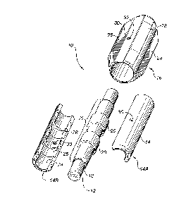
FIGURE 2 is an exploded perspective view of a rod
guide/sucker rod combination fabricated in accordance with the
teachings of the present invention.
DETAILED DESCRIPTION OF THE PREFERRED EMBODIMENT
The preferred embodiment, a rod guide/sucker rod
combination generally identified by reference numeral 10, will
now be described with reference to FIGURES 1 and 2.
Referring to FIGURE 1, completed rod guide/sucker rod
combination 10 has as components a sucker rod 12, split sleeve
14 and an overlying sleeve 16.

CA 02214230 1997-08-27
Referring to FIGURE 2, the method of fabricating rod
guide/sucker rod combination 10 involves the following steps.
The first step involves providing a sucker rod 12 having an
exterior surface 18 with a raised profile 20. As sucker rod
12 does not come with such a raised profile, raised profile 20
is, preferably, injection molded onto exterior surface 18 of
sucker rod 12. The configuration illustrated shows injected
molded portion 22, which forms raised annular profile 20. The
second step involves providing split sleeve 14. Split sleeve
14, as illustrated consists of two segments 14a and 14b. Split
sleeve 14 has an interior surface 24 with a recessed annular
profile 26 that mates with raised annular profile 20 of sucker
rod 12. As long as segments 14a and 14b are held together to
maintain recessed annular profile 26 in engagement with raised
annular profile 20, split sleeve 14 is secured against axial
movement relative to sucker rod 12. Split sleeve 14 is
preferably formed through an injection molding process. The
third step involves providing an overlying sleeve 16 that
overlies split sleeve 14 to maintain segments 14a and 14b of
split sleeve 14 in mating engagement with sucker rod 12.
Overlying sleeve 16 must be secured to split sleeve 14. It is
preferred that overlying sleeve 16 be injection molded over
split sleeve 14, in situ. Preferably overlying sleeve 16 has
a plurality of exterior vanes 28. Once this step is completed
rod guide/sucker rod combination 10 is ready to be taken and
installed at a field location. Referring to FIGURE 1, in order
to promote improved fluid flow, it is preferred that injection
moulded portion 22, split sleeve 14 and overlying sleeve 16 be
staggered to give the ends a stepped or generally conical
shape. If the materials used for moulded portion 22 and split
sleeve 14 are not self lubricating, it may be advisable to
provide a lubrication port 30 which extends through both
overlying sleeve 16 and split sleeve 14. In order to prevent
silt, sand and other abrasives from entering lubrication port
30, it may be advisable to position a filter element 32 in
lubrication port 30.

CA 02214230 1997-08-27
It will be apparent to one skilled in the art that the
component parts of rod guide/sucker rod combination 10 can be
fabricated from any suitable material, such as nylon,
polyethylene, polyphenylene sulfide, or polyphthalamide. It
will also be apparent to one skilled in the art that any
desired configuration of vanes 28. It will finally be apparent
to one skilled in the art that modifications may be made to the
illustrated embodiment without departing from the spirit and
scope of the invention as hereinafter defined in the Claims.

Representative Drawing
A single figure which represents the drawing illustrating the invention.
Administrative Status

2024-08-01:As part of the Next Generation Patents (NGP) transition, the Canadian Patents Database (CPD) now contains a more detailed Event History, which replicates the Event Log of our new back-office solution.

Please note that "Inactive:" events refers to events no longer in use in our new back-office solution.

For a clearer understanding of the status of the application/patent presented on this page, the site Disclaimer , as well as the definitions for Patent , Event History , Maintenance Fee  and Payment History  should be consulted.

Event History

Description Date
Inactive: IPC from MCD 2006-03-12
Time Limit for Reversal Expired 2002-08-27
Letter Sent 2001-08-27
Inactive: Inventor deleted 2000-06-06
Grant by Issuance 2000-04-11
Inactive: Cover page published 2000-04-11
Pre-grant 2000-01-07
Inactive: Final fee received 2000-01-07
Notice of Allowance is Issued 1999-11-17
4 1999-11-17
Letter Sent 1999-11-17
Inactive: Approved for allowance (AFA) 1999-10-28
Amendment Received - Voluntary Amendment 1999-09-27
Letter Sent 1999-08-05
Request for Examination Received 1999-07-22
Request for Examination Requirements Determined Compliant 1999-07-22
All Requirements for Examination Determined Compliant 1999-07-22
Application Published (Open to Public Inspection) 1999-02-27
Classification Modified 1998-01-02
Inactive: First IPC assigned 1998-01-02
Inactive: IPC assigned 1998-01-02
Inactive: Filing certificate - No RFE (English) 1997-11-05
Letter Sent 1997-11-05
Application Received - Regular National 1997-11-03

Abandonment History

There is no abandonment history.

Maintenance Fee

The last payment was received on 1999-07-22

Note : If the full payment has not been received on or before the date indicated, a further fee may be required which may be one of the following

  • the reinstatement fee;
  • the late payment fee; or
  • additional fee to reverse deemed expiry.

Patent fees are adjusted on the 1st of January every year. The amounts above are the current amounts if received by December 31 of the current year.
Please refer to the CIPO Patent Fees web page to see all current fee amounts.

Fee History

Fee Type Anniversary Year Due Date Paid Date
Application fee - small 1997-08-27
Registration of a document 1997-08-27
MF (application, 2nd anniv.) - small 02 1999-08-27 1999-07-22
Request for examination - small 1999-07-22
Final fee - small 2000-01-07
MF (patent, 3rd anniv.) - small 2000-08-28 2000-06-22
Owners on Record

Note: Records showing the ownership history in alphabetical order.

Current Owners on Record
RG INDUSTRIES LTD.
Past Owners on Record
THOMAS HUBERT VERMEEREN
Past Owners that do not appear in the "Owners on Record" listing will appear in other documentation within the application.
Documents

To view selected files, please enter reCAPTCHA code :


To view images, click a link in the Document Description column (Temporarily unavailable). To download the documents, select one or more checkboxes in the first column and then click the "Download Selected in PDF format (Zip Archive)" or the "Download Selected as Single PDF" button.

List of published and non-published patent-specific documents on the CPD .

If you have any difficulty accessing content, you can call the Client Service Centre at 1-866-997-1936 or send them an e-mail at CIPO Client Service Centre.

({010=All Documents, 020=As Filed, 030=As Open to Public Inspection, 040=At Issuance, 050=Examination, 060=Incoming Correspondence, 070=Miscellaneous, 080=Outgoing Correspondence, 090=Payment})


Document
Description 
Date
(yyyy-mm-dd) 
Number of pages   Size of Image (KB) 
Description 1997-08-26 5 187
Abstract 1997-08-26 1 16
Claims 1997-08-26 2 41
Drawings 1997-08-26 2 41
Claims 1999-09-26 3 93
Drawings 1999-09-26 2 53
Representative drawing 2000-03-06 1 13
Representative drawing 1999-03-21 1 9
Courtesy - Certificate of registration (related document(s)) 1997-11-04 1 116
Filing Certificate (English) 1997-11-04 1 164
Reminder of maintenance fee due 1999-04-27 1 111
Acknowledgement of Request for Examination 1999-08-04 1 193
Commissioner's Notice - Application Found Allowable 1999-11-16 1 164
Maintenance Fee Notice 2001-09-23 1 179
Correspondence 2000-01-06 1 37