Note: Descriptions are shown in the official language in which they were submitted.
CA 02214357 1997-09-12
WO 96/29198 PCT1L1S96/03564
-1-
SHEET WITH INTEGRAL FASTENER
Background of the Invention
Field of the Invention
The invention relates to sheet material with integral fasteners for
securing the sheet material to a structural member. In one of its aspects, the
invention relates to a sound barrier mat having an integral fastener for
securing
the mat to a vehicle fire wall. In another of its aspects, the invention
relates to
a method for assembling a sheet material to a structural wall. In still
another of
its aspects, the invention relates to a structural wall assembly comprising a
structural wall and a sheet material fastened thereto.
Description of Related Art
In most contemporary automobiles, a steel fire wall separates the
engine compartment from the passenger compartment. To reduce the
transmission of sound from the engine compartment through the fire wall and
into the passenger compartment, a sound barrier mat is mounted to and
substantially overlies the fire wall.
The sound barrier mat is mounted to a plurality of studs extending
from the surface of the fire wall. Typically, to mount the sound barrier mat
to
the fire wall, the sound barrier mat has corresponding apertures in register
with
the studs so that the studs extend through the apertures and hang the sound
barrier mat on the fire wall.
An absorber mat is usually attached to the sound barrier mat.
When the sound barrier mat is installed to the fire wall, the absorber mat
reduces the area of contact between the sound barrier mat and the fire wall.
The sound barrier mat will lay under the carpet and extends beyond the carpet
up to the top of the fire wall. To secure the sound barrier mat to the fire
wall,
separate fasteners are mounted onto the studs. The fasteners prevent the
accidental removal or repositioning of the sound barrier mat and the
underlying
absorber mat.
A fastener for attaching an article such as a trim strip to a motor
vehicle body is disclosed in U.S. Patent 5,291,6392 Baum et al., issued March
8,
1994. The Baum fastener is a plastic, push-button fastener which consists of a
domed head with a circular stem that is received at one end in a circular
skirt.
CA 02214357 1997-09-12 p ~r~~ ~b /03 5 64
~PEs!~~ 15 OCT 1996
-2-
A pair of resilient fingers project into an axial bore of the stem. To attach
the
fastener to the vehicle, a threaded stud mounted to the car body is received
within the axial bore of the stem. By exerting pressure on the push-button,
the
stem is pressed over and onto the stud to deflect the retaining fingers so
that
they engage the threads on the stud to secure the fastener to the body panel.
The domed head abuts the trim strip to hold the trim strip to the vehicle
body.
Other similar fasteners are disclosed in U.S. Patent Nos. 4,874,276,
issued October 17, 1989; 5,014,369, issued May 14, 1991; 5,195,793, issued
March 23, 1993; and 1,197,906, issued September 12, 1916.
Summary of Invention
According to the invention, a sheet material for mounting on a
wall with a stud extending from the wall has a fastener integrally formed with
the sheet material and an opening therethrough adapted to receive the stud and
be retained securely thereon. The fastener has a protrusion with the opening
at
a central portion of the protrusion. In one embodiment, the protrusion has a
hemispheric shape. In another embodiment, the protrusion has a conical shape.
Preferably, the fastener opening is slotted and defines multiple
flaps which can be deformed as the stud is pushed through the fastener
opening.
Typically, the stud is threaded and the flaps engage the threads of the stud
to
securely mount the dome to the stud. Preferably, the portion of the protrusion
forming the flaps is greater in thickness than the rest of the protrusion to
stiffen
the flaps. The protrusion preferably has a hollow interior.
In one embodiment, the fastener is spaced from the sheet by a
flexible web so that the fastener can be rotated to a position overlying the
sheet.
In another embodiment, the fastener is integrally formed within the sheet and
receives the stud as the sheet is mounted onto the wall.
The invention also contemplates a structural wall assembly
comprising a structural wall having at least one stud projecting thereof and a
sheet material as described above is mounted to the structural wall.
In one embodiment, the stud is threaded and the fastener engages
the threads of the stud. In another embodiment, the stud comprises a T-shaped
flange and the fastener has a slot at an acute angle to the plane of the
fastener.
AMENDED SHEET
CA 02214357 1997-09-12 ~ ~~~~ ~6 /03 5 b ~.
tPEA/C3S 15 0 C T 1996
-3-
Further, according to the invention, a method of assembling a
sheet material with at least one aperture to a structural wall having at least
one
stud extending therefrom comprises the steps of integrally forming a fastener
with the sheet material, the fastener having an opening for receiving the at
least
one stud, mounting the sheet material to the structural wall by aligning the
at
least one aperture with the at least one stud and moving the sheet material
toward the structural wall to insert the at least one stud through the at
least one
aperture. The sheet material is then secured to the structural wall by
aligning
the fastener opening with the at least one stud and moving the fastener toward
the structural wall to insert the at least one stud through the fastener
opening.
Preferably, the sheet material is injection molded.
The invention provides for quick and inexpensive assembly of a
sheet material, such as an absorber mat to a structural wall such as a fire
wall in
an automobile. The invention eliminates the need for separate fasteners which
must be secured to the stud after the sheet is mounted to the wall. The
integral
nature of the fasteners results in a more cost effective way of mounting a
sheet
material to a wall.
Brief Description of the Drawings
The invention will now be described with reference to the
drawings wherein:
FIG. 1 is a perspective view of a vehicle sound barrier mat
incorporating the integral fastener according to the invention;
FIG. 2 is a sectional view of a fastener illustrated in the
disassembled condition;
FIG. 3 is a plan view of the first embodiment of the integral
fastener illustrated in FIG. 2 in the disassembled condition;
FIG. 4 is an elevational view in section of the integral fastener of
FIG. 2 in the fastened position;
FIG. 5 is a plan view of a second embodiment of the integral
fastener according to the invention;
FIG. 6 is a sectional view taken along the line 6-6 in FIG. 5;
AMENDED SHEET
CA 02214357 1997-09-12 ~~~~~~ 96 l ~'.~ ~
~p~~ 15 OCT 1996
-4-
FIG. 7 is an elevational view in section of a third embodiment of
the integral fastener according to the invention in a disassembled condition;
FIG. 8 is a plan view of the integral fastener in FIG. 7; and
FIG. 9 is an elevational view in section of the integral fastener of
FIG. 7 in the fastened position.
Description of the Preferred Embodiments
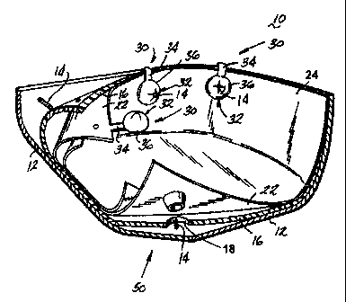
FIG. 1 illustrates a typical fire wall assembly 10 incorporating the
integral or unitary fastener 30 according to the invention. The fire wall
assembly 10 comprises a fire wall 12, which separates the engine compartment
from the passenger compartment of an automobile. The fire wall 12 is generally
made of steel and has a plurality of threaded studs 14 extending therefrom.
The
studs 14 are most often placed about the periphery of the fire wall 12;
however,
depending on the application, the studs 14 can be positioned within the
interior
of the fire wall 12.
The fire wall 12 is substantially covered by an absorber mat 16,
which has a plurality of apertures 18 corresponding to and in register with
the
studs 14. The absorber mat 16 is oriented with respect to the fire wall 12 so
that the apertures 18 align with the studs 14. When the absorber mat 16 is
placed against the fire wall 12, the studs 14 extend through the apertures 18
and
the absorber mat 16 is suspended from the studs 14.
A sound barrier mat 22, preferably made of thermoplastic olefin,
overlies the absorber mat and separates the absorber mat 16 from a layer of
carpet 24, which faces the passenger compartment. The sound barrier mat 22,
like the absorber mat 16, has a plurality of apertures 26 through the studs 14
extend to hang or suspend the sound barrier mat 22 from the fire wall 12. The
sound barrier mat 22 has a number of integral fasteners 30, each of which is
associated with a sound barrier mat aperture 26.
Referring to FIGS. 2 through 4, the integral fastener 30 comprises
a fastener or cap 32 connected to the sound barrier mat 22 by a web 34. The
cap 32 and web 34 are an integral part of the sound barrier mat 22 and are
preferably injection molded as a single part.
AMENDED SHEET
CA 02214357 1997-09-12
t~~ ~ 5 o c T ~~~b
_5-
In its preferred form, the cap 32 is a hollow hemispherical dome
36 having a circular, open bottom 38 and a cross-shaped aperture 40 at the top
of the dome 36. The cross-shaped aperture 40 defines multiple flaps 42 in the
surface of the dome 36 and which are flexible with respect to the dome 36. The
thickness of the dome 36 is substantially uniform, except that the portion of
the
dome 36 surrounding and including the flaps 42 can have a greater thickness to
give the flaps more rigidity. The diameter of the aperture 40 is less than the
diameter of the studs.
To assemble the fire wall assembly 10, the sound barrier mat 22,
with the absorber mat 16, is positioned with respect to the fire wall 12 so
that
the sound barrier mat apertures 26 align with the studs 14. The sound barrier
mat 22 is mounted to the fire wall 12 so that the studs 14 extend through the
sound barrier mat apertures 26. Once the sound barrier mat 22 is hung from
the studs 14, each fastener 30 is mounted to its associated stud 14 by
positioning
the dome 36 above the stud 14 and pushing downwardly on the dome to force
the stud 14 through to the cross-shaped aperture 40. The downward force of
the dome deflects the flaps 42 a sufficient distance so that the stud 14
extends
through the cross-shaped aperture 40 of the dome 36. The inherent resiliency
of
the flaps 42 presses the flaps 42 against the sides of the threaded stud 14
where
the flaps engage the threads of the stud 14 to prevent the inadvertent removal
of the dome 36.
Advantageously, because the fastener is integrally connected to the
sound barrier mat 22 by the web 34, the fastener 32 is always within easy
reach
of the installer, permitting the simple and quick installation of the sound
barrier
mat. Also, there is no longer a need for the installer to keep a stockpile of
separate fasteners, which can be dropped or misplaced during assembly.
The integral fastener 30 is most suited for use on studs 14
positioned near the periphery of the sound barrier mat 22. However, in certain
applications, it is desirable to locate the studs more interior of the
periphery of
the sound barrier mat 22. In those instances, the studs 14 can extend from an
interior portion of the fire wall 12. FIGS 5 and 6 illustrate a second
embodiment of the integral fastener according to the invention, which is
better
AMENDED SHEET
CA 02214357 1997-09-12 ~~~r~ ',~~ ~~ j 5 6 ~,
IPVEA/US 15 O~T »~6
-6-
suited for mounting the sound barrier mat 22 to a stud located interior of the
periphery of the fire wall 12. In the description of the second embodiment,
many of the elements are identical to the elements described in the first
embodiment. Therefore, like parts are identified by like numerals.
The second embodiment of the integral or unitary fastener 50
comprises a cup-shaped depression 52 formed in the sound barrier mat 22. The
cup-shaped depression 52 has an annular sidewall 54, which terminates in a
bottom wall 56 from which extends a protrusion having a cone-shaped portion
58. The cone-shaped portion 58 is truncated at its upper end to form an
aperture 60. Preferably, the diameter of the aperture 60 is slightly smaller
than
the diameter of the threaded stud 14 so that when the threaded stud is
inserted
through the aperture 60, the material forming the cone-shaped portion 58 is
deformed to fasten the sound barrier mat 22 to the stud 14.
The fire wall assembly 10 is assembled using the integral fastener
50 in much the same manner as previously described with respect to the first
embodiment of the integral fastener 30. The only substantive difference is
that
the aperture 60 of the cone-shaped portion 58 for the integral fastener 50 is
aligned with a stud 14. Once aligned, the integral fastener 50 is pressed
downwardly onto the stud 14 to force the threaded stud 14 through the aperture
60 of the cone-shaped portion, deforming the material comprising the cone-
shaped portion and fastening the sound barrier mat 22 to the threaded stud 14.
Although the integral fastener 50 is better suited for mounting to
studs positioned interiorly of the periphery of the fire wall as compared to
the
integral fastener 30, the integral fastener 50 is also suitable for mounting
to the
studs at the periphery of the fire wall. To mount to studs at the periphery of
the fire wall, the integral fastener 50 need only be molded in the sound
barrier
mat at the periphery thereof. The second embodiment can also be used to
improve the positioning of the sound barrier mat to the fire wall.
The first and second embodiments of the integral fastener mount
to a threaded stud extending from the fire wall. However, in some applications
it is desirable to use a flange or other similar planar element instead of the
stud.
FIGS 7 through 9 illustrate a third embodiment of an integral fastener 80
AMENDED SHEET
CA 02214357 1997-09-12
6PFAi15 O C T 1996
specifically designed to mount to a support wall or box having flanges instead
of
studs. Many of the elements in the third embodiment are similar to the
elements of the first and second embodiments. Therefore, like parts are
identified by like numerals.
In the third embodiment, a wall 70 has upstanding studs or flanges
72 having a head formed by outwardly directed ears 74, providing the flange 72
with a T-shaped profile. The line connecting the ears 74 defines a transverse
centerline. The absorber mat 16 is mounted to the wall in the same manner as
described above with respect to the first embodiment except that the apertures
18 are replaced by slots 76. Likewise, the sound barrier mat 22 has slots 78
adapted to receive the flange 72.
An integral or unitary fastener 80 is integrally molded with the
sound barrier mat 22 and comprises a fastener 82 and a web 84 connecting the
fastener to the sound barrier mat 22. The fastener 82 is substantially planar
and
has a retaining slot 86, which is oriented at an angle with respect to the
traverse
centerline of the flange 72.
In operation, the absorber mat 16 is mounted to the wall 70 by
inserting the flange 72 through the slots 76 of the absorber mat 16. Likewise,
to
mount the sound barrier mat 22, the flanges 72 are inserted through the slots
78
, of the sound barrier mat 22. The fastener 82 is then positioned over the
flange
72. The fastener 82 is rotated so that the retaining slot 86 aligns with the
transverse axes of the flange 72 and is pressed downwardly onto the flange 72
so
that the ears 74 extend through the retaining slot 86. Upon release of the
fastener 82, the inherent resiliency of the material comprising the integral
fastener 80 applies a torque or twisting motion to the fastener 82 to rotate
the
retaining slot 86 with respect to the flange 72 so they are no longer aligned.
In
this position, it is difficult for the fastener 82 to be inadvertently removed
from
the flange 72.
All three embodiments of the integral fastener permit the quick
and easy assembly of the fire wall assembly and the securing of the sound
barrier mat to the fire wall. Unlike separate fasteners, the integral fastener
according to the invention eliminates the stockpiling of separate fasteners
and
AMENDED SHEET
CA 02214357 1997-09-12
~PEAIU~ 15 OCT 1996
_8_
the slow down in assembly associated with the dropping or mishandling of the
separate fastener.
While particular embodiments of the invention have been shown,
it will be understood, of course, that the invention is not limited thereto
since
modifications may be made by those skilled in the art, particularly in light
of the
foregoing teachings. Reasonable variation and modification are possible within
the scope of the foregoing disclosure of the invention without departing from
the spirit of the invention.
AMENDED SHEET