Note: Descriptions are shown in the official language in which they were submitted.
CA 02214~4 1997-09-02
Title: Adapter for Inlerconnecting Optical Fiber Connectors.
Background of the invention.
5 1. Field of the Invention
The present invention relates to an adapter of the type used for interconnectingtwo optical fibers, for example in the situation where it is required to connect a testing
device, having an intPrn~l fiber, to an external fiber, for testing the external fiber or an
optical circuit to which it is connected.
2. Prior Art
There is a common need to provide te ~)Ol~y connections between an internal
optical fiber or fibers, which are part of testing equipment, and external fibers which are
to be them~Plves tested or which are parts of optical circuits to be tested. The testing
15 equipment is usually contained in a case having a panel providing terminals or "adapters"
which are connected intern~lly to a testing device, usually incorporating a laser light
source and/or a receiver, and which are capable of receiving connectors mounted on the
ends of the eYtern~l fibers. Sometimes the testing devices are permanently connected or
"hard wired" to the intPrn~l portions of the terminals. More commonly however, the
20 intPrn~l fibers have plug type connectors and the terminals are in the form of adapters
which have a double ended receptacle with an inner part ~cces~ihle from inside the panel
for receiving the intt~rn~l fiber connector, and an outer part on the outside of the panel
for receiving a plug type connector at the end of an external fiber.
It is common for the adapters to have an ~lignment sleeve which is a close fit on
25 ferrules fixed to the ends of edch of the connected optical fibers. Apart from this,
however, the connectors vary widely. Commonly used connectors are so-called FC
connectors, having a nut which engages an externally screw threaded barrel portion of
the adapter which surrounds the alignment sleeve, and ST connectors having a bayonet
type connection to a ~imil~rly located barrel. Still others, known as SC connectors, have
30 a rectangular plug which is a push fit into a rectangular socket and which is retained by
latches. One known testing appa dlus usually has internal fibers with FC type connectors.
However, the appandlus may need to be used with external fibers having different types
CA 02214~4 1997-09-02
of connectors, and it would clearly be advantageous to have adapters capable of being
changed to suit such different connectors.
Most adapters are designed to receive, in their opposite ends, two connectors ofsimilar type, but some are known which can receive different types of connector. For
5 example, U.S. Patent No. 5,073,042, which issued December 17, 1991 to Mulholland
et al., shows a hybrid adapter comprising two parts, one designed to receive an FC
connector, and the other to receive an SC connector, the two parts being joined by bolts.
Clearly, different arrangements can be made by mixing and matching different end parts.
However making such connections with bolts or the like is not practical for most users.
U.S. Patent No. 5,297,227, which issued March 22, 1994 to Brown et al., also
shows an adapter formed in two parts, i.e. an inner part and an outer part, connected by
the push fit of a cylin-1ric~l protrusion into a cylindrical housing. Each part can be one
suited to any particular type of connector, so that different parts can be combined in
different combinations depending on the types of connectors with which the optical fibers
15 to be tested are equipped. A series of the internal parts is held by an instrument panel,
and a series of the external parts is held by a mounting panel, the parts being held
together by fixing the mounting panel to the instrument panel. Apart from this the
adapters themselves do not have any means for holding the parts together.
U.S. Patent No. 5,333,222, which issued July 26, 1994 to Belenkiy et al., shows
20 an adapter formed of two parts which are held together by latch arms, but it seems that
this is a ~lll,anent connection and it is not intended that the parts be separated and used
with different parts.
A dirrelent approach is used by Diamond S.A., for example as described in U.S.
Patent No. 5,444,806, which issued August 22, 1995 to de Marchi et al. Here the panel
25 carries a plug type connector with a protruding ferrule, which mates with a sleeve
adapter which is movable and which has its outer end mated with another plug type
conne~ L. This has the drawback that the interior plug type connector is "hard-wired"
to the device inside the testing instrument, rather than being connected by a removable
connector as is usual, and when a device has to be added to the testing equipment, or
30 changed, its end connector usually has to be removed and the end of its fiber spliced to
a connector on the panel.
Another problem with the commonly used adapter arrangements, i.e. those in
which the adapter is fixed to the panel, is the difficulty of cleaning the ferrule at the end
CA 02214~4 1997-09-02
of the internal fiber; dirty ferrules cause a large plopollion of malfunctions in ap~al~lus
of this kind. While the external fiber ferrule projects from the end of the connector and
is easily cleaned, the internal fiber ferrule can usually only be cleaned by opening the
testing equipment case and removing the internal fiber connector from the adapter.
S Sometimes this is f~cilit~ted by making the panel removable, but this requires tools for
removing the panel. In any event, there is a possibility of ~l~m~ging the fiber by bending
it too sharply, or harming other delicate devices in the case. It would be desirable to
make the end of the intern~l fiber ferrule acces~ible from outside the case, for cle~ning
purposes.
It is one object of the invention to provide an adapter having two parts which are
readily separable, i.e. do not require removal of screws or the like, so that the outer part
can easily be adapted to the type of connector to be used.
It is a secondary object to provide an arrangement in which removal of the outer part
enables the int~rn~l fiber ferrule to be cleaned.
It is also desirable that the intern~l fiber ferrule be protected from cont~min~tion,
and that users' eyes be protected from laser light emitted from the internal fiber, when
there is no connector present. Some prior art designs deal with the cont~min~tion
problem by providing protective caps or dust covers which are a push fit onto the end
of the adapter; however such devices are easily lost, and are not effective in protecting
20 a user's eyes. In other desi~n~, a hinged shield has been used, which both prevents
cont~min~tion, and also protects an O~;ldtOl'S eyes. Such a shield is shown in U.S.
Patent No. 5,506,922, which issued April 9, 1996 to Grois et al., in the form of a flap
mounted on the flat side of a rectangular SC type receptacle. This design would not be
suitable for use with other types of adapter receptacle, most of which have a protruding
25 barrel portion which receives an outer sleeve and so could not accommodate the kind of
flap shown in Grois et al.
It is thus a further object of the invention to provide a shield or dust cover, both
for limiting cont~min~tion, and for ploteclillg a user's eyes, and which is suitable for
adapters designed for use with any commonly used connector type.
Summary of the Invention
In accordance with one aspect of the invention, there is provided an adapter forreceiving optical fiber connectors, having an inner part for connection to an internal
CA 02214=,=,4 1997-09-02
optical fiber having an internal end ferrule, and an outer part suitable for receiving an
external connector having an external optical fiber with an external end ferrule, the end
ferrules being received in an ~lignm~nt sleeve held within the adapter when bothconnectors are in place in the adapter,
wherein the outer part is readily separable from the inner part, the parts having
complementary eng~ging surf~ces, and having coopel~ting eng~gin~ means which allow
the two parts to be brought together with relative axial movement in one rotational
position of the parts, and which include c~mming and detent means which draw and lock
the two parts together upon relative rotation of one of the parts to a second rotational
10 position relative to the other.
The terms "inner" and "outer" are used herein to differentiate the two parts in
relation to the normal panel mounting; however these terms are not intende~l to restrict
the invention to adapters which are mounted on a panel or any other piece of appaldt~ls.
When the parts are used on a panel, the inner part will normally be mounted on the
15 outside of the panel and have a receptacle ~ccessihle from inside the panel for receiving
a connector carrying the intern~l fiber and its ferrule.
Preferably, the c~mming and detent means include part-circular grooves in the
inner part, having undercut C~mming surfaces termin~ting in recesses, and ret~ining
elem~nt~ projecting from the outer part, the retaining elements being movable through
20 entranceways into the grooves with relative axial movement of the parts in one relative
rotational position, and being capable of movement along said grooves upon relative
rotation of the parts, preferably through about 90~ and, in any event, less than 180~, to
the second rotational position at which the elements are retained in the recesses, these
recesses providing detent means. A resilient element may be provided between the two
25 parts, with the detent means tending to prevent movement of the ret~inin g elements until
the resilient element is colllpl~ssed. The groove and ret~ining element arrangement is
contained within the same "footprint" area normally required of an adapter of this
general type, so does not re~uire additional space.
The provision of detent means as described means that the parts are positively
30 locked together and the outer part does not move when connectors are screwed onto or
unscrewed from this part, as might happen if the parts were connected by a simple
screw.
CA 02214~4 1997-09-02
Preferably, the alignment sleeve is retained in the outer part, and when this part
is separated from the inner part the internal ferrule is ~ces~ihle for cleaning.It is common for the ends of ferrules to be ~l~nted, so that two mating ferrulesmust be rotationally aligned. In order to meet the alignment re~uirements, the retaining
5 elements and entranceways are differentiated so that the two parts can be connected
together only in one particular rotational position. The parts have conventional means to
ensure that the ferrules of mating connectors are properly rotationally aligned relative to
the inner and outer parts.
In order to protect the internal ferrule against cont~min~tion, and also to protect
10 a user's eyes, the outer part preferably has a cap connected thereto by hinge means
which is biassed to close the cap over the ferrule of the internal fiber when no external
connector is present. For this purpose, the outer part has a partially flat side surface,
and the cap is connected to the outer part by a living hinge mounted on the flat side
surface. The cap is recessed to fit over standard adapter receptacles capable of receiving
15 FC, ST, SC, and preferably other types of connectors. The cap may be used on adapters
which do not have the coopeldting eng~ging means described above.
Brief Description of the drawings.
A prefelled embodiment of the invention will now be described by way of
20 example with reference to the accompallying drawings, in which;
Figure 1 is a perspective view of an adapter of this invention, as mounted on the
panel of an instrument case, with both internal and external connectors in place, and with
the panel cut away to show the internal connector;
Figure 2 is a similar but enlarged view of the whole adapter, removed from the
25 panel and from the connectors;
Figure 3 is a similar view similar to Figure 2, but with the two parts of the
adapter separated;
Figure 4 is a view of the main component of the outer part of the adapter;
Figure 5 is an underside view of the inner part of the adapter;
Figure 6 is a plan view of the adapter, with the cap closed;
Figure 7 is a sectional elevation on lines 7-7 of Figure 6;
Figure 8 is a further sectional elevation on lines 8-8 of Figure 6, and
CA 02214~4 1997-09-02
Figure 9 is a pt;r~peclive view of adapter parts of this invention suitable to
different connector types.
Detailed Description.
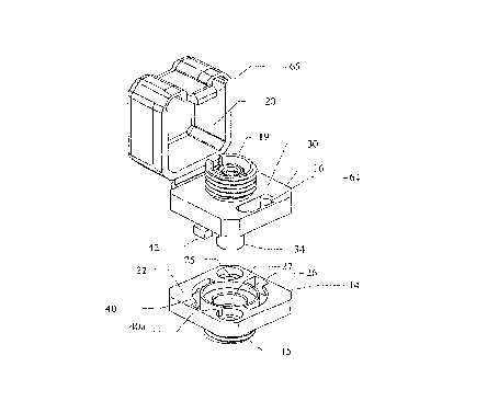
Referring to the drawings, Figures 1 and 2 show the adapter 10 of this inventionmounted on the panel P of the case of a testing instrument such as an ODTR (optical
time domain reflectometer). Within the testing instrument, a laser or other source is
connected to an internal fiber Fi, which terminates in an intern~l plug type connector 12
of well known form, usually an FC connector. As shown in Figure 1, connector 12 is
10 attached to the inner part 14 of the adapter 10, which is secured to the exterior of the
panel P by screws or the like, described below, while being intern~lly ~ces~ihle when
the case is opened. Removably secured to the part 14 is an outer (or upper) part 16,
suitable for receiving an çxt~rn~l conne~;lor 18 also of the FC type attached to the end
of an external fiber Fe. The connectors 12 and 18 are attached by being screwed onto
15 screwthreaded barrel portions 15 and 19 of the respective inner and outer parts. When
the eYt~rn~l connector 18 is removed from the adapter, a cap 20 automatically closes,
at least partially, over the outer end of the part 16, to protect the interior parts from
con~ tion, and also to protect a user's eyes from laser light; this is further described
below.
In Figure 3, the parts 14 and 16 are shown sepal~ted, while Figure 4 shows the
outer part disassembled. Further details of the parts are shown in Figures 5-8.
As seen in Figures 3, 5, 7 and 8, the inner part 14 has a square flange 22 with
the same ~imPn~ions as a regular flange type FC connector, from the lower side of
which extends the barrel 15. Opposite corners of the flange 22 have screw holes 25 for
25 mounting the flange to the exterior of the panel P, shown in Figures 1 and 7, at the sides
of an apt;llu~e in the panel through which the barrel 15 projects. The main upper face
of the flange 22 is flat, but its center has a circular well 26, surrounding a central socket
27.
The outer part 16 shown in Figures 3, 4, 7 and 8 has a flange 30 with a periphery
30 which is the same shape and size as the flange 22, and from the upper face of which
projects the threaded barrel portion 19. Part of its lower face is flat, and this, and the
upper face of the lower part flange 22, provide complementary eng~ging surfaces for the
parts 14 and 16. From the bottom of the flange 30 there projects a cylinder 34 which
CA 02214~4 1997-09-02
surrounds a socket 35 leading to an axial bore of smaller diameter than the socket. This
axial bore receives a split alignment sleeve 36 of standard design and which is suitable
for receiving and ~ligning two opposed 2.5 mm. ferrules. The sleeve 36 is received at
its upper end within a recess in a bushing 37 projecting axially within the barrel 19, and
S is held in place by a ret~ining collar 38 which is a push fit into the socket 35. When the
part 16 is fitted to part 14 the exterior surface of the cylinder 34 is located by being a
close fit into the socket 27 in the center of the inner part 14, these parts providing an
accurate centP.ing system. As is conventional, when connectors are in place the end
ferrules of their fibers meet at about the center of the ~lignmPnt sleeve 36.
The outer part 16 is connected to the inner part 14 by a quick release mechanismconstit~lted by undercut, part circular grooves 40 formed in the flange 22 of the inner
part 14, and cooperating rePining elements 42 projecting down from the outer part 16.
Each of the grooves 40 subtends about 90~ at the center of the adapter part. Each
groove has a wide entranceway 40a at a first end, the remainder of the groove being
lS undercut on its outer side to the same width as the entranceway so as to have an
overh~nging outer wall 40b. This outer wall 40b provides a c~mmin~ surface whichslopes inwardly, i.e. towards the face of the flange 22, and termin~tes in end recesses
each separated from the main part of the outer wall by a detent surface 40c, seen in
Figure S.
The grooves 40 are each designed to receive one of two ret~ining elements 42,
each of which has a relatively thin, depending leg portion 42a termin~ting in anoutwardly projecting foot portion 42b. The foot portions 42b are sized so that when the
inner and outer parts are united the foot portions can pass through the entranceways 40a,
and as the outer part is rotated relative to the inner part through about a right angle, the
25 foot portions pass along the c~."",ing surfaces 40b until they enter the recesses beyond
the detents 40c. A resilient O-ring 44 fitted onto cylinder 34 prior to assembly is
received within the well 26, and is compressed during engagement of the two parts. The
detents 40c provide an anti-turn feature since the O-ring must be compressed before the
foot portions can be moved out of these detents, so that the parts are not liable to be
30 sepaldled accidentally.
As shown in Figure 4, one of the foot portions 42b has a lateral projection 42b',
and this is sized to pass through one of the entranceways 40a which is larger than the
other. This ensures that the inner and outer parts of the adapter are rotationally aligned
CA 02214~4 1997-09-02
in a unique manner, so that ferrules with angled ends will fit together correctly.
Furthermore, the barrel portions 15 and 19 have notches 50 and 51 to receive the usual
keys (not shown) of the connectors and rotationally align them so that the ferrules are
~lopelly ~lignPA,
If the outer connector 18 is removed, and the outer adapter part 16 is then
se~al~led from the inner part 14, with the inner connector 12 still in place, the ~lignment
sleeve 36 is retained in the outer part 16 by the ret~ining collar 38. This means that the
inner fiber end ferrule is exposed within the well 26 of the inner part, and is accessible
for c1e~ning.
As mentioned above, the outer connector part 16 carries cap 20 which
autom~tic~lly covers the outer end of this part when no connector is present. The cap
is formed as a plastic molding, as best shown in Figures 4 and 8, and is integrally
connected by a "life" or living hinge 60 to leaf or flange 62 having screw holes, by
which the flange can be fixed to threaded holes 63 in a flat rear side surface of the outer
15 part flange 30. The hinge 60 is such that it biasses the cap towards the closed position
when no connector is present on the barrel 19, but does not close it completely since that
would require a greater spring force. On the front side of the outer part the flange 30
has an elongated apel~u~ 64 sized to receive a detent 65 projecting down from the front
side of the cap. The flexibility of the cap allows the detent to bend inwards and to be
20 retained by a catch type formation on the inner face of the aperture 64 when the cap is
fully closed. It is released by pushing in the front of the cap.
As indicated above, a central feature of this invention is that it permits an adapter
to be readily connected to different optical fiber circuits, merely by replacing the outer
part 16 by one suited to a different connector. Figure 9 shows, as examples, a range of
25 different outer parts which can be used. In addition to the FC part 16, there is an
adapter part 16a suited to an HMS connector, a part 16b suited to a Din 2.5 connector,
a part ~6c suited to an SC connector, a part 16d suited to an ST connector, and a part
16e suited to an E2000 connector. As shown, each of these parts has intereng~ging
means corresponding to the ret~ining elements 42 described above. Also, each has screw
30 holes suitable for receiving the flange part 62 of a cap, which can be the same cap 20
already described and which is suitable for all the types of the connector parts, since the
interior of the cap can accommodate the projections of the parts such as part 16, 16a,
16b, and 16d.
CA 02214~4 1997-09-02
Although the above-described embodiment is for a testing device, the invention
embraces adapters for other purposes, such as patch panels of telecommunications central
offices, or other situations where a fiber is to be connected through a panel to another
fiber or a device.
Although the above-described embodiment uses ferrules of 2.5 mm. diameter,
which are widely used, the invention is applicable to adapters for connectors having other
sizes of ferrule.