Note: Descriptions are shown in the official language in which they were submitted.
CA 02214642 1997-09-04
TITLE OF THE INVENTION
INTERNET INFORMATION DISPLAYING APPARATUS
BACKGROUND OF THE INVENTION
The present invention relates to an Internet information
displaying apparatus for receiving information through the
Internet, taking in the information, converting into video
signals, and displaying on a CRT display or the like.
Recently, owing to the wide popularity of personal
computers, information is transmitted and received widely by
using the Internet.
The Internet is a network of multiple computers
connected on a global scale, and various pieces of readable
information are stored in individual computers. These pieces
of information include E-mails, various programs, and home
pages, which can be communicated in two ways. The home page
corresponds to the title and table of contents of a piece of
information, and by selecting a graphic pattern (icon) or a
-word on the home page, the necessary information can be
reviewed.
Therefore, recently, more an more users are using the
Internet as the site of information presentation. It is the
WWW (World Wide Web) that is noticed as the server for
providing such information.
The reason why the WWW server is drawing attention is
CA 02214642 1997-09-04
mainly due to the wide spread of the client software
(browser) for retrieving information by using a graphical
menu. By the development of such browser, it becomes easier
to search information on the network, and the traffic volume
to the WWW server increased rapidly, and the users have come
to notice as the publicity media, and many users have come to
use.
To read information of the WWW server, as mentioned
above, the browser is needed. For example, the browser is
disclosed in pages 164 to 167 of "Internet Handbook for
Corporate Users", an extra output of Nikkei Communications
published by Nikkei BP (November 30, 1994).
On the other hand, to review the information of WWW
server by the Internet, conventionally, it was necessary to
install the browser in the personal computer.
FIG. 1 is a schematic diagram showing a conventional
connection example of computer and Internet. In this
connection example, a personal computer 107 is connected to a
-communication line 102 through a modem 108 or a terminal
adapter, and through the communication line 102, it is ~
further connected to a modem 103 or a terminal adapter of a
provider which is a connection service firm. The modem 103
is connected to a server 104 which is the computer of the
provider.
The server 104 is connected to the Internet 106 around
CA 02214642 1997-09-04
the clock through a router 105 for setting a trunk route.
From the personal computer 107, a telephone call is made
when necessary, and a connection is made to the Internet 106
through the server 104 of the provider (dial-up connection).
Among those not owning personal computer, there are many
people wanting to use the Internet, but not daring to buy a
personal computer. Some are hesitant to operate the personal
computer. Among those people, it seems many people want to
use the Internet, if possible, without using the personal
computer.
In such background, lately, the Internet television
allowing to use the Internet easily by the television
receiver is proposed. That is, the Internet information is
displayed by using the television receiver in the general
household as the display of the personal computer.
Accordingly, without having to purchase a personal computer,
only a device for receiving the Internet information is built
in or attached to the television receiver, and such device is
easy to handle as compared with the personal computer, and
the television receiver functions its original purpose while
not reviewing the Internet information, which is very
convenient for the user.
However, to review the information of WWW server of the
Internet by such television receiver, it is necessary to
connect once to the provider through the communication line.
CA 02214642 1997-09-04
Only by connecting the communication line with the provider,
the information can be acquired.
This connection by the communication line is made
through a modem, and the users of personal computer who make
communications can judge if connection is made or not as
follows. That is, since the modem is sending data by sound
signal and can be monitored, it is judged if the data is
communicated or the telephone is connected by the sound.
Incidentally, when a function for receiving the Internet
is incorporated in the television receiver, it is possible to
wait while watching the television broadcast while connecting
to the provider, and such function is generally desired
because the user can wait without being bored until
connected.
However, in case of receiving a television broadcast by
television receiver or the like, it is usual for the sound of
the television broadcast to be cast on a speaker of a
receiver. In such case, in connecting a communication line,
the judgment as to whether the connection is made by the
sound from the modem or not cannot be made because the sound
from the modem cannot be heard due to the casting through the
speaker of the sound from the television broadcast.
The above fact is the same not only in the case of
viewing the television program on the television broadcast
but also while viewing the video signals from the VTR (video
CA 02214642 1997-09-04
-
tape recorder) or LD (laser disk) player.
The present invention has been developed in the light of
the situation as above, and its principal object is to make
the connection condition by telephone line easily
recognizable even under the condition where the video signal
such as a television signal is being received and the sound
is outputted from the speaker in an Internet information
dlsplaying apparatus like a television receiver equipped with
Internet receiving function.
BRIEF SUMMARY OF THE INVENTION
The first aspect of an Internet information displaying
apparatus according to the present invention comprises:
television signal receiving means for receiving a television
signal; video signal outputting means for outputting a video
signal by extracting from the television signal received by
the television signal receiving means; displaying means for
displaying the video signal outputted by the video signal
outputting means; sound signal outputting means for
outputting a sound signal by extracting from the television
signal received by the television signal receiving means;
audible sound generating means for generating the sound
signal as audible sound outputted by the sound signal
outputting means; modulating/demodulating means for
transmitting and receiving the digital data through a
CA 02214642 1997-09-04
-
telephone line by converting the digital data into a carrier
signal by sound in transmitting, and by demodulating the
carrier signal by sound into digital data at receiving; data
converting means for transmitting digital data to the
modulating/demodulating means and receiving digital data from
the modulating/demodulating means, and converting said
received digital data into a video signal; converted video
signal outputting means for outputting the output from the
data converting means to the displaying means; carrier signal
outputting means for outputting the carrier signal by the
transmitting/receiving sound of the modulating/demodulating
means; and telephone line sound outputting means for giving
sound signal generated in the telephone line to the audible
sound generating means and generating as audible sound.
The second aspect of the Internet information displaying
apparatus according to the present invention is that the
first aspect further comprises: character signal generating
means for generating a character signal and outputting it to
the displaying means; and character signal generation
controlling means for detecting a transmitting/receiving
condition of the digital data by the modulating/demodulating
means, and controlling the character signal generating means
so as to generate a character signal to indicate the
transmitting/receiving condition.
Further, the third aspect of the Internet information
CA 02214642 1997-09-04
-
displaying apparatus according to the present invention is
characterized in that, in the first and the second aspects,
the telephone line sound outputting means inputs the signal
including the carrier signal from the carrier signal
outputting means, and outputs it by mixing with the sound
signal to the audible sound generating means.
Further, the fourth aspect of the Internet information
displaying apparatus according to the present invention is
that the first aspect further comprise sound volume
controlling means for controlling the sound signal outputting
means.
Further, the fifth aspect of the Internet information
displaying apparatus according to the present invention is
characterized in that, in the fourth aspect, the sound volume
controlling means controls the output level of the sound
signal from the sound signal outputting means to become lower
in case of mixing the output from the telephone line sound
outputting means and outputting it to the audible sound
~ generating means.
Further, the sixth aspect of the Internet information
displaying apparatus according to the present invention is
characterized in that, in the fourth aspect, the sound volume
controlling means controls to make the output level of the
sound signal from the sound signal outputting means ~0~ in
case of mixing the output from the telephone line sound
CA 02214642 1997-09-04
i~
outputting means and outputting it to the audible sound
generating means.
The seventh aspect of the Internet information
displaying apparatus according to the present invention
comprises: television signal receiving means for receiving a
television signal; video slgnal outputting means for
outputting a video signal by extracting from the television
signal received by the television signal receiving means;
displaying means for displaying the video signal outputted by
the video signal outputting means; sound signal outputting
means for outputting a sound signal by extracting from the
television signal received by the television signal receiving
means; audible sound generating means for generating the
sound signal as audible sound outputted by the sound signal
outputting means; dial sound generating means for generating
a signal of the dial sound from a telephone line;
modulating/demodulating means for transmitting and receiving
the digital data through a telephone line by converting the
digital data into a carrier signal by sound at transmitting,
and by demodulating the carrier signal by sound into digital
data at receiving; data converting means for transmitting
digital data to the modulating/demodulating means and
receiving digital data from the modulating/demodulating
means, and converting the received digital data into a video
signal; converted video signal outputting means for
CA 02214642 1997-09-04
-
outputting the output from the data converting means to the
displaying means; carrier signal outputting means for
outputting the carrier signal by the transmitting/receiving
sound of the modulating means; and telephone line sound
outputting means for outputting the dial sound signal and the
carrier signal to the audible sound generating means.
The eighth aspect of the Internet information displaying
apparatus according to the present invention is that the
seventh aspect further comprises: character signal generating
means for generating a character signal, and outputting it to
the displaying means; and character signal generation
controlling means for detecting a transmitting/receiving
condition of the digital data by the modulating/demodulating
means, and controlling the character signal generating means
so as to generate a character signal to indicate the
transmitting/receiving condition.
Further, the ninth aspect of the Internet information
displaying apparatus according to the present invention is
characterized in that, in the seventh and eighth aspects, the
telephone line sound outputting means controls to make the
signal level of the dial sound to be outputted lower
according to the dial sound signal generated by the dial
sound generating means.
Further, the tenth aspect of the Internet information
displaying apparatus according to the present invention is
CA 02214642 1997-09-04
-
characterized in that, in the seventh and eighth aspects, the
telephone line sound outputting means controls to make the
signal level of the dial sound to be outputted lower in case
the dial sound outputted from the dial sound generating means
is a pulse type.
Further, the eleventh aspect of the Internet information
displaying apparatus according to the present invention is
characterized in that, in the seventh and eighth aspects, the
telephone line sound outputting means inputs the signal
including the carrier signal from the carrier signal
outputting means, and outputs it by mixing with the sound
signal to the audible sound generating means.
Further, the twelfth aspect of the Internet information
displaying apparatus according to the present invention is
characterized in that, in the seventh and eighth aspects
further comprises pseudo dial sound generating means for
outputting a signal of pseudo dial sound instead of the dial
sound from the telephone line sound outputting means.
Further, the thirteenth aspect of the Internet
information displaying apparatus according to the present
invention is characterized in that, in the twelfth aspect,
- the telephone line sound outputting means outputs the signal
of pseudo dial sound generated by the pseudo dial sound
generating means according to the dial sound signal generated
by the dial sound generating means.
CA 02214642 1997-09-04
Further, the fourteenth aspect of the Internet
information displaying apparatus according to the present
invention is characterized in that, in the twelfth aspect,
the telephone line sound outputting means outputs the signal
of pseudo dial sound generated by the pseudo dial sound
generating means instead of the dial sound signal from the
telephone line sound outputting means, in case the dial sound
from the dial sound generating means is a pulse type.
Further, the fifteenth aspect of the Internet
information displaying apparatus according to the present
invention is characterized in that, in the twelfth aspect,
the telephone line sound outputting means inputs the signal
including a carrier signal from the carrier signal outputting
means, and outputs it by mixing with the sound signal to the
audible sound generating means.
The above and further objects and features of the
invention will more fully be apparent from the following
detailed description with accompanying drawings.
BRIEF DESCRIPTION OF THE SEVERAL VIEWS OF THE DRAWINGS
FIG. 1 is a schematic diagram showing the conventional
example of connection of a computer with Internet;
FIG. 2 is a schematic diagram showing an example of
connection of an Internet television as an Internet
information displaying apparatus according to the present
CA 02214642 1997-09-04
invention with Internet;
FIG. 3 is a block diagram showing an example of
constitution of the first embodiment of the Internet
information displaying apparatus according to the present
invention;
FIG. 4A is a flow chart showing an example of operation
of the first embodiment of the Internet information
displaying apparatus according to the present invention;
FIG. 4B is a flow chart showing an example of operation
of the first embodiment of the Internet information
displaying apparatus according to the present invention;
FIG. 5A is a schematic diagram showing an example of
screen display of the first embodiment of the Internet
information displaying apparatus according to the present
invention;
FIG. 5B is a schematic diagram showing an example of
screen display of the first embodiment of the Internet
information displaying apparatus according to the present
invention;
FIG. 5C is a schematic diagram showing an example of
screen display of the first embodiment of the Internet
information displaying apparatus according to the present
invention;
FIG. 6 is a flow chart showing an example of operation
of the second embodiment of the Internet information
CA 02214642 1997-09-04
-
displaying apparatus according to the present invention;
FIG. 7 is a time chart showing an example of operation
of the second embodiment of the Internet information
displaying apparatus according to the present invention;
FIG. 8 is a block diagram showing the constitution of
the third embodiment of the Internet information displaying
apparatus according to the present invention;
FIG. 9 is a flow chart showing an example of operation
of the third embodiment of the Internet information
displaying apparatus according to the present invention;
FIG. lOA is a schematic diagram showing an example of
screen display of conventional Internet information
displaying apparatus;
FIG. lOB is a schematic diagram showing an example of
screen display of conventional Internet information
displaying apparatus;
FIG. lOC is a schematic diagram showing an example of
screen display of conventional Internet information
displaying apparatus;
FIG. 11 is a block diagram showing an example of
constitution of the fourth embodiment of the Internet
information displaying apparatus according to the present
invention; and
FIG. 12 is a time chart showing an example of operation
of the fourth embodiment of the Internet information
CA 02214642 1997-09-04
displaying apparatus according to the present invention.
DESCRIPTION OF THE PREFERRED EMBODIMENTS
Hereinafter, embodiments of the present invention will
be illustrated with reference to the drawings.
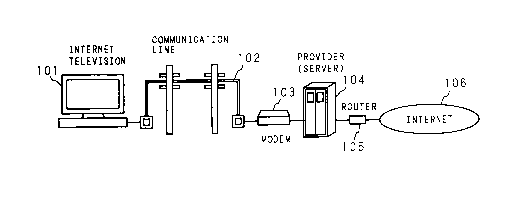
FIG. 2 is a schematic diagram showing an example of
connection of an Internet television as an Internet
information displaying apparatus according to the present
invention with Internet.
According to this connection example, the Internet
television 101 is connected with a communication line 102.
In the Internet television 101, a modem is built in. The
communication line 102 is connected with a modem 103 or a
terminal adapter of a provider which is a connection service
company, and the modem 103 is connected to a server 104 which
is a computer of the provider.
The server 104 is connected to the Internet 106 around
the clock, and is connected to the Internet 106 through a
router 105 for setting the trunk route.
By predetermined operation, telephone call operation is
automatically made from the Internet television 101, and
connection is made with the Internet 106 through the server
104 of the provider (dial up connection).
FIG. 3 is a block diagram showing an example of
constitution of the first embodiment of the Internet
14
CA 02214642 1997-09-04
-
television receiver as the Internet information displaying
apparatus according to the present invention.
In FIG. 3, reference numeral 1 is a tuner, which carries
out channel selection of the television wave inputted from
the antenna 100 by the control from a microcomputer 14. The
television wave selected by the tuner 1 is converted into an
intermediate frequency by a VIF (video intermediate
frequency) circuit 2 and given to a video detector 3. In the
video detector 3, the video signal is detected, and outputted
to the first switching unit 5 by amplified with the video
amplifier 4.
To a first switching unit 5, there are inputted an
output of the above video amplifier 4, an output of an OSD
circuit 15 to be described later, and an output of a video
output amplifier 19 for amplifying the video signal outputted
by an Internet circuit 18. The first switching unit 5
outputs one of video signals to a CRT (cathode ray tube) 6
under control of the microcomputer 14.
Reference numeral 7 shows an SIF (sound intermediate
frequency) circuit which detects an SIF signal from the
output of the VIF circuit 2 and gives to a sound detector 8.
In the sound detector 8, the sound signal is detected, and
outputted to the second switching unit 10 by amplified with a
sound amplifier 9.
To the second switching unit 10, there are inputted the
CA 02214642 1997-09-04
output of the above sound amplifier 9 and an output of an
sound output amplifier 20 for amplifying the sound signal
outputted by the Internet circuit 18 to be described later.
The second switching unit 10 outputs one of sound signals to
a mixing circuit 11 by the control of the microcomputer 14.
To the mixing circuit 11, the output of the second
switching unit 10 as described above and an output of a
carrier amplifier 17 as described later are inputted, and the
both are mixed to output to a speaker 12. Whereas the
speaker 12 is shown in FIG. 3, there may be provided a
headphone, earphone, etc. which generate audible sound
instead of the above or in combination.
Reference numeral 13 shows a remote control unit or an
operating unit of the front panel of the television receiver
1 (both not shown). By operating it with user, various
instructions can be given to the microcomputer 14. The
microcomputer 14 carries out various controls of the
television receiver 1 according to the diversified
instructions given from the outside by the user.
Reference numeral 15 shows the on-screen display circuit
(hereinafter to be referred to as OSD circuit), which
generates various on-screen character signals under control
of the microcomputer 14 and outputs it to the first switching
unit 5 as described above.
Reference numeral 16 is a modem, which is connected to a
16
CA 02214642 1997-09-04
-
telephone line, and 17 is a carrier amplifier for amplifying
the carrier sound from the modem 16.
Reference numeral 18 shows the Internet circuit, which
receives an information data of Internet given from the modem
16 and converts it to a video signal, and outputs sound
signal. The video signal outputted from the Internet circuit
18 is amplified by the video output amplifier 19 and
outputted to the first switching unit 5. The sound signal
outputted from the Internet circuit 18 is amplified by the
sound output amplifier 20 and outputted to the second
switching unit 10.
Next, the operation of the television receiver as the
Internet information displaying apparatus of the present
invention as above is explained.
At first, in viewing television broadcast, when the user
operates the operating unit 13 to select the desired channel,
a tuning voltage adapted to the selected channel is supplied
to the tuner 1 from the microcomputer 14. And, the
- television signal of the selected channel is inputted to the
VIF circuit 2, and the video signal is extracted by thè video
detector 3 and inputted to the video amplifier 4. On the
other hand, in the SIF circuit 7, an SIF signal is detected
from the output of the VIF circuit 2, and further, in the
sound detector 8 the sound signal is extracted and supplied
to the sound amplifier 9.
CA 02214642 1997-09-04
While the television broadcast is received, the
television receiver outputs a video signal to the CRT 6
through connection of the first switching unit 5 to the video
amplifier 4 by the microcomputer 14. By connecting the
second switching unit 10 to the sound amplifier 9, the
microcomputer 14 supplies a sound signal to the speaker 12
through the mixing circuit 11. With respect to the sound
signal, adjustment of the sound volume is feasible by
controlling the sound amplifier 9. This can be realized by
the control of the sound amplifier 9 by the microcomputer 14
through operation of the operating unit 13 by the user.
On the other hand, in case the channel has been
selected, the microcomputer 14 controls the OSD circuit 15 so
as to generate a character signal to indicate the channel
number. As a result, the character signal is outputted to
the first switching unit 5 from the OSD circuit 15. At this
time, the microcomputer 14 controls so that the first
switching unit 5 inputs the character signal outputted from
the OSD circuit 15 and outputs it to the CRT 6.
The OSD circuit 15 can carry out various displays of not
only the channel character as described above but also the
displays in connection with the sound volume adjustment,
various adjustment modes, etc.
Next, with respect to the operation of the television
receiver as an Internet information displaying apparatus of
18
CA 02214642 1997-09-04
the present invention in the case of receiving Internet
information, the operation is explained with reference to the
flow chart of FIG. 4A and FIG. 4B.
At first, when the user operates the operating unit 13
to select an Internet connection mode (Sl), the microcomputer
14 controls the OSD circuit 15 so as to switch over the
display from the screen of receiving the television broadcast
to the Internet menu screen (to show various information
menus such as traveling, stock, etc.). When the user
operates the operating unit 13 to select the desired
information from the menu screen (S2), the microcomputer 14
transfers the data to the Internet circuit 18, and the
Internet circuit 18 causes the modem 16 to start connection
of the telephone line with the provider (S3). At this time,
the microcomputer 14 changes over the menu screen to the
television broadcast screen.
In case of not being the Internet connection mode, the
screen remains receiving the television broadcast (S10).
When the modem 16 connects the telephone line (connected
with the provider), carrier sound is outputted from the modem
16 (S4). Simultaneously with it, the information to indicate
the start of connection of the telephone line is transmitted
from the modem 16 to the Internet circuit 18, and further the
information is supplied to the microcomputer 14.
On receipt of the information, the microcomputer 14
19
CA 02214642 1997-09-04
controls to lower the output level of the sound amplifier 9
for amplifying the sound signal of the television broadcast
to a predetermined level. The sound signal whose sound
volume has been lowered to a predetermined level by the sound
amplifier 9 and the carrier sound outputted from the modem 16
are mixed by a mixing circuit 11, given to the speaker 12,
and generated as audible sound (S5). By such operation, due
to the automatic lowering of the sound volume of television
broadcast, the carrier sound of the modem 16 can be heard
even when the user is viewing the television broadcast.
Furthermore, in order to allow the user to hear the
carrier sound more clearly, the output level of the carrier
amplifier 17 is simultaneously controlled by the
microcomputer 14 to increase the level of the carrier sound,
thereby making it possible for the user to hear the carrier
sound of the modem 16 more clearly. And furthermore, it may
be so arranged that, by setting the output level of the sound
amplifier 9 to ~0~, the sound signal of the television
broadcast is muted to make only the carrier sound of the
modem 16 outputted from the speaker 12.
From the microcomputer 14, a character signal indicating
the fact of telephone line being connected is generated in
the OSD circuit 15 and displayed by CRT 6 along with the
television signal (S6). With respect to the example of
display in this case, a message 32 ~Connection is in
CA 02214642 1997-09-04
progress. Please wait for a while." is displayed on the
lower part of the screen 30, as shown in the schematic
diagram of FIG. 5A. Alternatively, besides the message 32, a
timer 31 may be displayed to give indication of the
connecting time. In addition, in carrying out sound volume
adjustment, the change of the signal having the mixture of
the carrier sound and the sound signal may be allowed for the
user to recognize visually by bar display outputted from the
OSD circuit 15.
Further, when the telephone line is connected to the
other party (provider), the data of the Internet information
is received from the modem 16, so that the information to
indicate completion of connection of the telephone line is
transmitted to the microcomputer 14 through the Internet
circuit 18 (S7).
By this operation, the microcomputer 14 controls the
sound amplifier 9 and returns the sound volume of the
television signal so as not to output the carrier sound (S8).
Further, as shown in the schematic diagram of FIG. 5B, by OSD
circuit 15, the connection time is displayed by the message
34 ~Connection has been completed~ and the display of the
timer 33 (S9).
In case of the connection with the Internet, the data
from the modem 16 are received in the Internet circuit 18 and
the video signal and sound signal are outputted. The video
CA 02214642 1997-09-04
signal is supplied to the first switching unit 5 through the
video output amplifier 19, and the sound signal is supplied
to the second switching unit lO through the sound output
amplifier 20, by which the information of the Internet can be
received through the CRT 6 and the speaker 12.
In case the connection of the telephone line cannot be
made in a predetermined time (no telephone line is connected)
(Sll), the microcomputer 14 controls the sound amplifier 9 in
a manner to return the sound volume of the sound signal of
the television signal to the original state to prevent the
carrier sound from being outputted (S8). Furthermore, as
shown in the schematic diagram of FIG. 5C, by the OSD circuit
15, the connection time is displayed by the message 36
"Connection has failed" and the display of the timer 35 (S9).
By the operation of the television receiver as an
Internet information displaying apparatus of the present
invention as above, the user can confirm the telephone line
connection status by both sound and visual sense.
By the way, by the speaker 12, the connecting state of
the telephone line is made audible not only in the carrier
sound as described above but also in a sound of dialing (dial
sound). The telephone line includes a pulse dial type and a
tone dial type, which respectively show different dial
sounds. Of these, the pulse dial is a type to generate
pulses by the switch which mechanically turns ON/OFF.
CA 02214642 1997-09-04
-
Accordingly, when the dial sound is outputted from the
speaker 12, a problem occurs such that "pop noise" is
generated to give unpleasant sound output.
In view of the above, in the second embodiment of the
Internet information displaying apparatus of the present
invention, the following countermeasures are taken to
decrease the unpleasant sound. Hereinafter, explanation is
given in reference to the flow chart of FIG. 6 and the time
chart of FIG. 7.
In this second embodiment, the constitution itself is
the same as that of Embodiment 1 shown in FIG. 3 above, and
the different portions are only a part of the software
controls of the microcomputer 14. Accordingly, in the
following description, only the different portions are
explained.
FIG. 6 is a flow chart showing the operation of the
second embodiment. In the flow chart of the first embodiment
shown in FIG. 4A and FIG. 4B above, the step S4 and the step
S5 are different, and in other steps the same-operations are
conducted, and therefore, the explanation on the part of the
same operation is omitted.
At first, the operation until the modem 16 connects the
telephone line with the provider (S3) is the same as that of
the first embodiment. When the telephone line is connected,
the microcomputer 14 confirms whether the present telephone
23
CA 02214642 1997-09-04
-
line is a pulse type or a tone type (S100). In case of it
being a pulse type, the microcomputer 14 confirms whether the
present time is the period during which the modem 16 is
generating the dial sound or not (dialing or not) (S101).
As a result, when the time is a dial pulse generating
period, the microcomputer 14 controls so that the sound
volume of the dial sound of the telephone line becomes
smaller (S102). This dial sound is outputted by mixing with
the sound signal of the television broadcast from the speaker
12 (S103). This processing is continued for the period in
which the dial sound is generated. When the dial pulse
generating period elapses, the microcomputer 14 controls to
make the sound volume of the dial sound of the telephone line
larger (S104). And, this dial sound of the telephone line
and the sound signal of the television broadcast are mixed
and outputted from the speaker 12 (S105). Needless to say,
it is allowable for the telephone line condition to be
on-screen displayed.
- In the meantime, in case the telephone line is a tone
type, the step may be advanced from step S100 to step S104
and the dial sound directly outputted with enlarged sound
volume or applied in the same manner as in the pulse type.
When the above condition is viewed by the time lapse,
the condition becomes as in the time chart shown in FIG. 7.
Namely, according to the pulse type, during the
24
CA 02214642 1997-09-04
non-connection with the Internet (a), the condition is
somewhat muted, in the period of dialing the telephone line
(b), the output sound volume of the modem 6 is small, in the
period (c) which is the communication stage with the
provider, the output sound volume of the modem 16 becomes
large, and in the Internet connected period (d), it is muted.
On the other hand, in the tone type, in the period of dialing
the telephone line (b) and the period of communication with a
provider, the output sound volume of the modem 6 is enlarged.
According to the second embodiment as above, the pop
noise caused by the pulse type dial sound can be decreased.
Besides the embodiments mentioned above, there may be
the third embodiment whose constitution example is shown in
the block diagram of FIG. 8.
In the block diagram shown in FIG. 8, a DSP (digital
signal processor) 37 is added to the constitution of the
first embodiment to generate pseudo sound. The DSP 37 may be
that built in the modem, or that additionally provided as a
extra circuit.
Hereinafter, based on the block diagram of FIG.8 and the
flow chart of FIG. 9, the operation of the third embodiment
is explained.
However, in the flow chart shown in FIG. 9 of the third
embodiment, the only point of change is that the step S102
shown in the flow chart of FIG. 6 in the second embodiment as
Z5
CA 02214642 1997-09-04
-
described above is changed to the step 106 which generates
the pseudo tone, and other operations are unchanged.
Accordingly, in case the telephone line is a pulse type
and dial sound is generated, in the dial pulse generating
period, under control of the microcomputer 14, DSP 37
generates the sound simulating dial sound like "pip-pop-pa"
in a tone type and outputs it to the speaker 12. At this
time, the actually generated dial sound is controlled so as
not to be outputted under control of the carrier amplifier 17
by the microcomputer 14. As to this pseudo tone, it may be
so arranged as to output tone type sound corresponding to the
pulse type sound, or utterly different effect sound.
As described in detail above, according to the third
embodiment of the present invention, even in case the user is
viewing the television broadcast, the connection operation
condition of the telephone line can be confirmed by the dial
sound.
By the ~ay, in an ordinary television receiver, it is
not the case for all the video signals received as television
broadcast to be displayed but only the range called an
effective scanning region in horizontal direction is
displayed on the CRT 6. Namely, the period for scanning in
horizontal direction is 63.5 ~s of ~hich the video signal is
in the period of 54.6 ~s. In a television receiver, display
is made only for about 49 ~s of the period (to be called an
26
CA 02214642 1997-09-04
-
effective scanning line region) excluding the period of 5% at
both ends of the video signal period (over-scanning region).
On the other hand, in the Internet information, due to
the display of characters and pictures over full screen
areas, when the images are converted into video signals, they
are formed as video signals including an over-scan region, as
previously mentioned. Accordingly, there is a problem that
partial characters and picture images in the original
Internet information come into the overscan region to make
the screen image invisible with a television receiver (ref.
FIG. lOB).
In order to prevent such a phenomenon, the Internet
displaying apparatus of the present invention is designed in
the following manner. Namely, in order to display the
Internet information on the CRT 6 of a television receiver in
the same manner as for displaying on a monitor for a personal
computer, it may be arranged to make display on a screen of
640 dots in the horizontal direction and 480 dots in the
vertical direction. To the convenience, because the number
of the effective scanning lines in the vertical direction of
the television receiver is 480, this can be easily realized.
In order to obtain such screen size, the 640 dots in the
horizontal direction may be met by the video signal region of
one clock (0.07 ~s) x 640 = 44.8 ~s because one clock is
14.3 MHz. This comes within the effective horizontal
27
CA 02214642 1997-09-04
scanning line region of 49 ~s which means that all the
Internet information is to be displayed (ref. FIG. 10A).
By the way, when display is made as described above, the
discontinued points of the video signals are also to be
displayed, in which case the right and left periods having no
video signal are set to black levels. However, as the video
signal level shows sharp changes at the border line between
the video signal and the black level, voltage fluctuation
occurs in the high voltage circuit.
Here, explanation is made on the voltage fluctuation of
the high voltage circuit. When a video signal level is
developed suddenly from the black level, though no beam
current of CRT 6 runs on a black level, on generation of a
video signal, the beam current naturally flows out. And, as
a high voltage is supplied to the CRT 6 from the high voltage
circuit, the high voltage changes due to the flow of the beam
current. This high voltage circuit is supplied from the fly
back transformer (FBT), and a deflection operation in the
horizontal direction is to be made from the FBT.
Accordingly, when the high voltage fluctuates, the deflection
current in the horizontal deflection also changes, in other
words, the amplitude changes, with the result that the size
of the picture image in the horizontal direction (lateral
direction) changes to give bend of picture images (ref. FIG.
lOA). Especially, such defect is remarkable at the boundary
28
CA 02214642 1997-09-04
-
of the video signals.
In a wide television receiver having an aspect ratio of
16:9, for example, the screen may be displayed in division
into two areas. Concretely, there may be arranged to display
a video signal of television broadcast on one screen, and a
video signal of the Internet on the other screen. Even in
such a case, it may be so arranged for the video signal
obtained from the Internet information to be displayed with
addition of the white level on the right and left boundaries
as described above.
In view of the situation as mentioned above, the
Internet information displaying apparatus of the present
invention has also a function to make the boundary of the
screen in which the Internet information is displayed less
conspicuous. Hereinafter, the fourth embodiment of the
Internet information displaying apparatus of the present
invention having such function is concretely explained.
FIG. 11 is a block diagram showing an example of
constitution of the fourth embodiment, which is made by
remodelling a part of the block diagram of FIG. 3 which shows
the constitution of the first embodiment abovementioned.
Namely, in the block diagram shown in FIG. 3, the video
signal outputted from the Internet circuit 18 is directly
inputted to the video output amplifier 19, but in this fourth
embodiment, a switch 21 is provided between the Internet
29
CA 02214642 1997-09-04
'_
circuit 18 and the video amplifier 19. This switch 21 is
connected at one input end to the level setting volume 23,
and at the other input end to the Internet circuit 18, with
the output end connected to the video amplifier 19. And, by
an output (switching signal) of the two input logic (OR)
circuits 22, the switch 21 is controlled. To one input of
the logic circuit 22 is inputted a BLK pulse from the
Internet circuit 18, and to the other input an HBLK pulse is
inputted from the non-illustrated horizontal deflection
circuit, respectively.
The constitution of other portions is the same as that
of the first embodiment shown in FIG. 3.
Next, the operation of this fourth embodiment is
explained with reference to the time chart of FIG. 12.
When a telephone line is connected and the Internet
information is sent to the Internet circuit 18 through the
modem 18, the Internet circuit 18 converts the Internet
information (digital data) into a video signal and outputs it
to the switch 21.
Also, to the other input end of the switch 21, a DC
level which has been adjusted by the level setting volume 23
is inputted. This DC level is set so that the white level of
the video signal becomes 30% - 50%.
On the other hand, from the Internet circuit 18, there
is outputted as shown by (b) in FIG. 12, the blanking (BLK)
CA 02214642 1997-09-04
'"_
pulse corresponding to the converted video signal period
which is shown by (a) in FIG. 12. Also, the horizontal
blanking (HBLK) pulse as shown by (c) in FIG. 12 for blanking
the preceding and succeeding periods of the horizontal
synchronizing signal is formed in the non-illustrated
horizontal deflection circuit. These BLK pulse and HBLK
pulse are inputted to the logic circuit 22, where a switching
signal for switching the switch 21 as shown by (b) in FIG. 12
is outputted.
Accordingly, when the switch 21 is controlled by the
switching signal which is an output signal of the logic
circuit 22, the switch 21 outputs the video signal from the
Internet circuit 18 to the video output amplifier 19 for the
period in which the switching signal is "H", and switches the
white level set by the level setting volume 23 to output to
the video output amplifier 19 during the period in which the
switching signal is ~L~. By this operation, there is
supplied to the video output amplifier 19 from the switch 21
~ a DC level voltage in which a white level is set to a video
signal as shown by (e) in FIG. 12.
The output from the video output amplifier 21 is
outputted to the CRT 6 and displayed as described above.
Accordingly, as shown in the above FIG. lOC, the right and
left portions of the video signal are displayed as the
predetermined white level (gray color), and the boundary with
CA 02214642 1997-09-04
-
the video signal becomes less conspicuous.
As described above, according to the fourth embodiment,
bend of picture images at the boundary between the video
signal and the right and left blanking periods can be
prevented, and the boundary thereof becomes less remarkable.
In the foregoing embodiments, description is made on the
cases of the Internet information displaying apparatus of the
present invention being applied to the television receiver,
but the application is not limited to it. For example,
reverse to the above embodiment, the Internet information
display may be realized by incorporating a function as a
television receiver on an ordinary personal computer with
which Internet communication is feasible.
As this invention may be embodied in several forms
without departing from the spirit of essential
characteristics thereof, the present embodiments is therefore
illustrative and not restrictive, since the scope of the
invention is defined by the appended claims rather than by
the description preceding them, and all changes that fall
within metes and bounds of the claims, or equivalence of such
metes and bounds thereof are therefore intended to be
embraced by the claims.
32