Language selection

Search

Patent 2214949 Summary

Third-party information liability

Some of the information on this Web page has been provided by external sources. The Government of Canada is not responsible for the accuracy, reliability or currency of the information supplied by external sources. Users wishing to rely upon this information should consult directly with the source of the information. Content provided by external sources is not subject to official languages, privacy and accessibility requirements.

Claims and Abstract availability

Any discrepancies in the text and image of the Claims and Abstract are due to differing posting times. Text of the Claims and Abstract are posted:

  • At the time the application is open to public inspection;
  • At the time of issue of the patent (grant).
(12) Patent: (11) CA 2214949
(54) English Title: METHOD AND APPARATUS FOR DELIVERING A CASED GLASS STREAM
(54) French Title: METHODE ET APPAREIL POUR DEVERSER UN FLUX DE VERRE DOUBLE
Status: Expired and beyond the Period of Reversal
Bibliographic Data
(51) International Patent Classification (IPC):
  • C03B 07/088 (2006.01)
  • C03B 07/00 (2006.01)
  • C03B 07/08 (2006.01)
  • C03B 07/094 (2006.01)
  • C03B 07/096 (2006.01)
  • C03B 17/02 (2006.01)
(72) Inventors :
  • SCOTT, GARRETT L. (United States of America)
(73) Owners :
  • OWENS-BROCKWAY GLASS CONTAINER INC.
(71) Applicants :
  • OWENS-BROCKWAY GLASS CONTAINER INC. (United States of America)
(74) Agent: GOWLING WLG (CANADA) LLP
(74) Associate agent:
(45) Issued: 2004-08-24
(22) Filed Date: 1997-09-08
(41) Open to Public Inspection: 1998-03-20
Examination requested: 1999-09-29
Availability of licence: N/A
Dedicated to the Public: N/A
(25) Language of filing: English

Patent Cooperation Treaty (PCT): No

(30) Application Priority Data:
Application No. Country/Territory Date
08/716,918 (United States of America) 1996-09-20

Abstracts

English Abstract


Apparatus for forming a cased glass stream having an inner core glass
surrounded by an outer casing glass includes a spout for receiving core glass
from a first
source and delivering such glass through a first orifice. A second orifice is
vertically spaced
beneath and aligned with the first orifice, and is surrounded by an annular
chamber that
communicates with the second orifice through the gap between the first and
second orifices.
A tube delivers casing glass from a second source to the annular chamber in
such a way that
glass flows by gravity from the first and second sources through the orifices
to form the cased
glass stream. The core glass delivery spout includes a reservoir for receiving
and holding the
core glass, and having at least one lower opening of a first diameter. An
orifice ring is
positioned beneath the reservoir, and has at least one opening of second
diameter less than the
first diameter aligned with the first opening and forming the first orifice. A
collar of uniform
inside diameter equal to the first diameter extends from the first opening to
the orifice ring,
and thereby spaces the reservoir from the orifice ring so as to increase
hydrostatic head
pressure on glass flowing from the reservoir through the first orifice. The
core glass reservoir
is surrounded by a metal casing, and the casing glass delivery tube extends
through a notch in
the sidewall of the core glass casing. An air-cooled liner controls heat
transfer from the casing
glass delivery tube to the core glass reservoir.


Claims

Note: Claims are shown in the official language in which they were submitted.


Claims:
1. In a method of forming a glass stream comprising a first inner layer and a
second
outer layer which includes providing a spout having a first generally vertical
orifice,
delivering molten glass from a first source through said first orifice, and
delivering glass
from a second source such that the glass from said second source provides an
outer layer
about the glass from the first source, the improvement comprising:
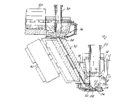
providing a resistance heated tube assembly, having an inlet end and an outlet
end
through which the glass flows from said second glass source for said outer
layer,
providing an electrically heated collar below said spout between said spout
and
said first orifice,
providing a second orifice in vertically spaced aligned relation below said
first
orifice,
providing an annular chamber around said second orifice,
positioning said tube assembly such that the inlet end receives glass from
said
second source and the outlet end delivers glass to said annular chamber,
delivering glass from said first source through said first orifice to and
through said
second orifice,
delivering glass from said second source from the outlet end of said
resistance
heated tube assembly to said annular chamber and between said first and second
orifices
such that said glass from said second source provides an outer layer to said
glass from
said first source, and glass flowing through said second orifice comprises
said first inner
layer and said second outer layer, and
providing a casing about said electrically heated collar and providing a
generally
vertical notch in said casing into which said outlet end of said tube assembly
is
positioned.
2. The method set forth in claim 1 including providing cooling means adjacent
to
said notch.
-7-

3. The method set forth in claim 2 wherein said step of providing cooling
means
comprises providing an air cooled heat exchanger between said casing and said
tube
assembly within said notch, and delivering cooling air through said heat
exchanger.
4. The method set forth in claim 1 wherein said step of providing said casing
comprises making said casing of non-magnetic metal.
5. The method set forth in claim 1 wherein said step of providing said casing
comprises making said casing of stainless steel.
6. In a method of forming a glass stream comprising a first inner layer and a
second
outer layer which includes providing a spout having a first generally vertical
orifice,
delivering molten glass from a first source through said first orifice, and
delivering glass
from a second source such that the glass from said second source provides an
outer layer
about the glass from the first source, the improvement comprising:
providing a resistance heated tube assembly having an inlet end and an outlet
end
through which the glass flows from said second glass source for said outer
layer,
providing a second orifice in vertically spaced aligned relation below said
first
orifice,
providing an annular chamber around said second orifice,
positioning said tube assembly such that the inlet end receives glass from
said
second source and the outlet end delivers glass to said annular chamber,
delivering glass from said first source through said first orifice to and
through said
second orifice,
delivering glass from said second source from the outlet end of said
resistance
heated tube assembly to said annular chamber and between said first and second
orifices
such that said glass from said second source provides an outer layer to said
glass from
said first source, and glass flowing through said second orifice comprises
said first inner
layer and said second outer layer, and
-8-

providing a casing about said first source and providing a generally vertical
notch
in said casing into which said outlet end of said tube assembly is positioned.
7. The method set forth in claim 6 including providing cooling means adjacent
said
notch.
8. The method set forth in claim 7 wherein said step of providing cooling
means
comprises providing an air cooled heat exchanger between said casing and said
tube
assembly within said notch, and delivering cooling air through said heat
exchanger.
9. The method set forth in claim 6 wherein said step of providing said casing
comprises making said casing of non-magnetic metal.
10. The method set forth in claim 6 wherein said step of providing a casing
comprises
making said casing of stainless steel.
11. In an apparatus for forming a glass stream comprising a first inner layer
and a
second outer layer which includes a spout having a first generally vertical
orifice, means
for delivering molten glass from a first source through said first orifice,
and means for
delivering glass from a second source such that the glass from said second
source
provides an outer layer about the glass from the first source, the improvement
comprising:
a resistance heated tube assembly having an inlet end and an outlet end
through
which the glass flows from said second source for the outer layer,
an electrically heated collar below said spout between said spout and said
first
orifice,
a second orifice in vertically spaced relation below said first orifice,
an annular chamber around said second orifice, said tube assembly being
positioned such that the inlet end receives glass from said second source and
the outlet
end delivers glass to said annular chamber, such that glass from said first
source is
-9-

delivered through said spout, said first orifice and said second orifice in
sequence, and
glass from said second source flows from the outlet end of said resistance
heated tube
assembly to said annular chamber and between said first and second orifices
such that
said glass from said second source provides an outer layer to said glass from
said first
source, and glass flowing through said second orifice comprises said first
inner layer and
said second outer layer, and
a casing about said electrically heated collar, said casing including a
generally
vertical notch in said casing in which said outlet end of said resistance
heated tube
assembly is disposed.
12. The apparatus set forth in claim 11 including cooling means adjacent said
notch.
13. The apparatus set forth in claim 12 wherein said cooling means comprises
an air
cooled heat exchanger in said notch between said casing and said tube assembly
and
means for delivering cooling air through said heat exchanger.
14. The apparatus set forth in claim 11 wherein said casing is made of non-
magnetic
metal.
15. The apparatus set forth in claim 11 wherein said casing is made of
stainless steel.
16. In an apparatus, for forming a glass stream comprising a first inner layer
and a
second outer layer which includes a spout having a first generally vertical
orifice, means
for delivering molten glass from a first source through said orifice, and
means for
delivering glass from a second source such that the glass from said second
source
provides an outer layer about the glass from the first source, the improvement
wherein
said means for delivering glass from said second source comprises:
a resistance heated tube assembly having an inlet end and an outlet end
through
which the glass flows from said second source for the second outer layer,
-10-

said tube assembly being positioned such that the inlet end receives glass
from
said second source, and
a casing surrounding said means for delivering glass from said first source
and
having a generally vertical notch in which said outlet end of said resistance
heated tube
assembly is disposed.
17. The apparatus set forth in claim 16 including cooling means adjacent said
notch.
18. The apparatus set forth in claim 17 wherein said cooling means comprises a
an
air-jacketed liner plate between said casing and said tube assembly and means
for
delivering cooling air through said liner plate.
19. The apparatus set forth in claim 16 wherein said casing is made of non-
magnetic
metal.
20. The apparatus set forth in claim 16 wherein said casing is made of
stainless steel.
21. In an apparatus for forming a cased glass stream having an inner core
glass
surrounded by an outer casing glass, said apparatus including a spout for
receiving core
glass for a first source and delivering such glass through a first orifice,
means forming
a second orifice vertically spaced beneath and aligned with said first orifice
with an
annular chamber surrounding said second orifice and communicating with said
second
orifice through a gap between said first and second orifices, and means for
delivering
casing glass from a second source to said annular chamber such that glass
flows by
gravity through said orifices from said first and second sources to form said
cased glass
stream, the improvement in which said spout comprises:
a reservoir for receiving and holding said core glass and having at least one
lower
opening of a first diameter,
-11-

an orifice ring positioned beneath said reservoir and having at least one
opening
of second diameter less than said first diameter aligned with said at least
one lower
opening of said first diameter and forming said first orifice, and
a collar of uniform inside diameter equal to said first diameter extending
from
said at least one lower opening to said orifice ring and thereby spacing said
reservoir from
said orifice ring so as to increase hydrostatic pressure on glass at said
first orifice from
said reservoir,
said collar and said reservoir forming an abutment joint surrounding said at
least
one lower opening, and said apparatus further comprising means for cooling
said joint
so as to control leakage of glass through said joint, said cooling means
comprising a
hollow band surrounding said joint and means for delivering cooling air to
said band, said
band being circumferentially segmented around said collar for accommodating
thermal
expansion of said collar, clamp means for holding said band in place around
said joint,
and spring means for maintaining clamping pressure on segments of said band
while
accommodating expansion as a result of heating of said reservoir and collar.
22. The apparatus set forth in claim 21 further comprising heating means
disposed
externally around said collar for heating said collar and thereby promoting
flow of glass
from said reservoir through said collar.
23. The apparatus set forth in claim 22 wherein said heating means comprises
electrical heating means.
24. The apparatus set forth in claim 22 wherein said collar is of ceramic
composition.
25. The apparatus set forth in claim 24 wherein said collar has a metal liner
extending
from said at least one lower opening to said orifice ring for preventing
leakage of glass
through said collar.
-12-

26. ~The apparatus set forth in claim 21 wherein said spout further comprises
a casing
surrounding said reservoir, said casing having a notch through which extends
said means
for delivering casing glass from said second source to said annular chamber.
27. In an apparatus for forming a cased glass stream having an inner core
glass
surrounded by an outer casing glass, said apparatus including a spout for
receiving core
glass for a first source and delivering such glass through a first orifice,
means forming
a second orifice vertically spaced beneath and aligned with said first orifice
with an
annular chamber surrounding said second orifice and communicating with said
second
orifice through a gap between said first and second orifices, and means for
delivering
casing glass from a second source to said annular chamber such that glass
flows by
gravity through said orifices from said first and second sources to form said
cased glass
stream, the improvement in which said spout comprises:
a reservoir for receiving and holding said core glass and having at least one
lower
opening of a first diameter,
an orifice ring positioned beneath said reservoir and having at least one
opening
of a second diameter less than said first diameter aligned with said at least
one lower
opening of said first diameter and forming said first orifice,
a collar of uniform inside diameter equal to said first diameter extending
from
said at least one lower opening to said orifice ring and thereby spacing said
reservoir from
said orifice ring so as to increase hydrostatic pressure on glass at said
first orifice from
said reservoir, and
a casing surrounding said reservoir, said casing having a notch through which
extends said means for delivering casing glass from said second source to said
annular
chamber.
28. ~The apparatus set forth in claim 27 wherein said collar and said
reservoir form an
abutment joint surrounding said at least one lower opening, and wherein said
apparatus
further comprises means for cooling said joint so as to control leakage of
glass through
said joint.
-13-

29. The apparatus set forth in claim 28 wherein said cooling means comprises a
hollow band surrounding said joint and means for delivering cooling air to
said band.
30. The apparatus set forth in claim 29 wherein said band is circumferentially
segmented around said collar for accommodating thermal expansion of said
collar.
31. The apparatus set forth in claim 30 further comprising clamp means for
holding
said band in place around said joint.
32. The apparatus set forth in claim 31 wherein said clamp means includes
spring
means for maintaining clamping pressure on segments of said band while
accommodating
expansion as a result of heating of said reservoir and collar.
33. The apparatus set forth in claim 27 wherein said means for delivering
casing glass
comprises a heated tube, and wherein said apparatus further comprises means in
said
notch for controlling heat transfer between said tube and said casing.
34. The apparatus set forth in claim 33 wherein said means in said notch
comprises
an air cooled heat exchanger.
-14-

Description

Note: Descriptions are shown in the official language in which they were submitted.


CA 02214949 2003-O1-31
METHOD AND APPARATUS FOR DELIVERING A CASED GLASS STREAM
The present invention is directed to delivery of a glass stream for forming
glass
charges for glassware manufacture, and more particularly to a method and
apparatus for
delivering a so-called cased glass stream in which an inner or core glass is
surrounded by
an outer or casing glass layer.
Background and Summary of tl~e Invention
It has heretofore been proposed to provide a cased glass stream for forming
glassware having layered wall segments. U.S. Patents 5,776,221 and 5,855,640
disclose
techniques for delivering such a cased glass stream in which core glass from a
first source
is delivered through a first orifice. A second orifice is vertically spaced
beneath and
aligned with the first orifice, and is surrounded by an annular chamber that
communicates
with the second orifice through the gap between the first and second orifices.
A heated tube
delivers casing glass from a second glass source to the annular chamber that
surrounds the
second orifice. Glass flows by force of gravity from the first and second
sources through
the first and second orifices in such a way that a cased glass stream emerges
from the
second orifice. This cased glass stream may be sheared by conventional
techniques to form
individual cased glass gobs for delivery to conventional individual section
glassware
forming machines.
Although the techniques disclosed in the noted patent applications address and
overcome problems theretofore extant in the art, further improvements remain
desirable.
For example, it has been found desirable to increase the gravitational force
that forces the
core glass through the orifice so as to increase flow rate and uniformity of
the cased glass
stream. Furthermore, the heated tube that delivers the casing glass to the
annular chamber
passes closely adjacent to the core glass reservoir, and it has been found
desirable to control heat

CA 02214949 1997-09-08
exchange between the casing glass delivery tube and the core glass reservoir
and glass delivery
elements. It is therefore a general object of the present invention to provide
a method and
apparatus for delivering a cased glass stream of the described character in
which hydrostatic
head pressure on the core glass stream is increased without deleteriously
affecting core glass
delivery, and in which heating of the core glass stream is closely controlled
for optimum
performance and reduced leakage.
Apparatus for forming a cased glass stream having an inner core glass
surrounded by an outer casing glass includes a spout for receiving core glass
from a first
source and delivering such glass through a first orifice. A second orifice is
vertically spaced
beneath and aligned with the first orifice, and is surrounded by an annular
chamber that
communicates with the second orifice through the gap between the first and
second orifices.
A tube delivers casing glass from a second source to the annular chamber in
such a way that
glass flows by gravity from the first and second sources through the orifices
to form the cased
glass stream. In accordance with the present invention, the core glass
delivery spout includes
a reservoir for receiving and holding the core glass, and having at least one
lower opening of
first diameter. An orifice ring is positioned beneath the reservoir, and has
at least one opening
of second diameter less than the first diameter aligned with the first opening
and forming the
first orifice. A collar of uniform inside diameter equal to the first diameter
extends from the
first opening to the orifice ring, and thereby spaces the reservoir from the
orifice ring so as
to increase hydrostatic head pressure on glass flowing from the reservoir
through the first
orifice.
The collar is externally surrounded by an electrical resistance-heating
element
for heating the collar and thereby promoting flow of glass from the reservoir
through the
collar, particularly during initiation of glass flow. The collar in the
preferred embodiment of
-2-

CA 02214949 1997-09-08
the invention is of ceramic composition, and has an inner liner of metal such
as platinum for
preventing leakage of glass through the collar in the event of fracture. The
collar and the
reservoir form an abutment joint surrounding the opening at the bottom of the
reservoir, and
this joint is cooled to control leakage of glass through the joint. The joint
cooling mechanism
preferably comprises a segmented hollow band through which cooling air flows.
In accordance with another aspect of the present invention, the core glass
reservoir is
surrounded by a protective casing. A vertically oriented notch or pocket is
formed in this
casing for receiving the heated casing glass delivery tube. An air-cooled
metal band heat
exchanger is positioned in the casing notch between the casing and the tube to
control heat
transfer between the tube and the casing, and thus between the casing glass
delivery tube and
the core glass reservoir.
Brief Description of the Drawings
The invention, together with additional objects, features and advantages
thereof,
will be best understood from the following description, the appended claims
and the
accompanying drawings in which:
FIG. 1 is a fragmentary elevational schematic diagram of a glass delivery
system in accordance with a presently preferred embodiment of the invention;
FIG. 2 is a fragmentary sectional view on an enlarged scale of a portion of
the
delivery system illustrated in FIG. 1;
FIG. 3 is a sectional view taken substantially along the line 3-3 in FIG. 2;
FIG. 4 is a sectional view taken substantially along the line 4-4 in FIG. 2;
FIG. 5 is an exploded plan view of the reservoir/collai cooling assembly
illustrated in FIG. 4; and
-3-

CA 02214949 2003-O1-31
FIG. 6 is sectional view of one of the cooling band elements illustrated in
FIG. 5.
Detailed Description of Preferred Embodiments
FIG. 1 illustrates a system 10 for delivering a stream of cased glass. A first
forehearth 12 delivers core glass to a reservoir or bowl 14 that has at least
one opening
16 (usually several openings) at the lower end thereof. Reservoir 14 is
surrounded by a
protective casing 18, preferably constructed of non-magnetic metal such as
stainless steel.
A tube 20 controls delivery of core glass from reservoir 14 through opening 16
to and
though a first orifice 22 carried by an upper orifice ring 24 beneath
reservoir 14. A lower
orifice ring 26 carries a second orifice 28 positioned beneath orifice 22 and
axially
aligned therewith. Orifice 28 is surrounded by an annular chamber 30 formed
between
orifice rings 22, 26. Chamber 30 communicates with orifice 28 by means of a
lateral
space or gap between orifices 22, 28. Annular chamber 30 is coupled by a
delivery tube
32 to the opening 34 at the lower end of a casing glass spout 36. Spout 36
includes a
delivery control tube 38, and is coupled to a casing glass forehearth 40.
Delivery tube
32 is resistance heated by control electronics 42 for maintaining flow of
casing glass to
chamber 30. To the extent thus far described, system 10 in FIG.1 is
essentially the same
as disclosed in the above-noted U.S. Patents Nos. 5,776,221 and 5,855,640. The
former
of such applications is directed in particular to construction of casing glass
delivery tube
32, while the latter of such applications is directed in particular to
construction of orifice
rings 24, 26.
FIG. 2 illustrates core glass spout 13 in greater detail. An extension collar
44
extends from the lower end of reservoir 14 to the upper end of orifice ring
24. Collar 44 has
-4-

CA 02214949 2003-O1-31
a uniform inside diameter equal to the diameter of opening 16 In reservoir 14
and greater than
the inside diameter of orifice 22 in orifice ring 24. Collar 44 is preferably
of ceramic
composition, as are reservoir bowl 14 and orifice ring 24. Collar 44 thus
serves to elevate
reservoir 14 with respect to orifice ring 24 so as to increase hydrostatic
pressure on the core
glass that flows from reservoir 14 through orifice 22, and thereby increase
both core glass and
casing glass flow rates. Collar 44 is surrounded by an electrical resistance
heating element 46
(FIGS. 2 and 3) to boost heating of collar 44 from that caused by conduction
from gas burner
assemblies at reservoir 14 and lower orifice ring 26. Such heating of collar
44 helps promote
core glass flow, particularly during startup. A cylindrical sheath 48 of
platinum or other
corrosion-resistant metal lines the inner surface of collar 44, having an
outwardly projecting
circumferential flange 50 captured between the lower end of reservoir bowl 14
and the upper
end of collar 44. Platinum sheath 48 prevents leakage of glass through
extension collar 44 in
the event of cracking or fracture of the latter. A lip may also be formed at
the lower end of
sheath 48 to help reenforce the sheath and hold it in position over collar 44.
Inasmuch as reservoir 14 and collar 44 comprise different ceramic castings,
glass can leak at the joint between the lower end of the reservoir bowl and
the upper end of
the collar. Externally applied heat to collar 44 can aggravate this leakage,
and prevent slowing
and hardening of leaking glass by devitrification. In order to cool this joint
enough to cause a'
glass devitrification and thereby arrest leakage, an air-cooled metal band 52
(FIGS. 2 and 4-6)
radially outwardly surrounds this joint. Band 52 comprises four identical
hollow arcuate
segments 54. Each segment has an inlet 56 which interiorily extends from one
end into the
:hollow segment to adjacent the opposing end, and from which air can flow
along the inner wall
surfaces of each segment to an air outlet 58. The four segments 54 are clamped
in end-
adjacent position surrounding the reservoiricollar joint by means of a clamp
ring 60. Clamp
-5-

CA 02214949 1997-09-08
ring 60 is circumferentially compressed by means of a coil spring 62, which
accommodates
expansion of clamp ring 60 and cooling band 52 caused by thermal expansion of
collar 44 and
reservoir 14. Joint temperature is monitored and cooling air is routed through
band 52 so as
to maintain the temperature of the joint sufficiently low so as to cause
devitrification of glass
leakage, while sufficiently high to insure that devitrified glass crystals do
not form within the
main glass stream.
Delivery tube 32 extends downwardly from casing glass spout 36 closely
adjacent to and intersecting core glass reservoir casing 18. In order to
accommodate passage
of delivery tube 32, a pocket or notch 64 is formed in the sidewall of casing
18. This notch
or pocket allows delivery tube 32 to nest closer to orifice ring 24 and
orifice 22. An air-
jacketed metal liner plate 66 is disposed within notch 64 between delivery
tube 32 and the
material of casing 18. Air flow is directed through plate 66 to maintain plate
66 and casing
18 at a temperature low enough to reduce glass leakage while hot enough to
minimize thermal
disturbances to glass flow either through orifice 22 or delivery tube 32.
Cooling air is
delivered to plate 66 by means of inlet tubes 68.
-6-

Representative Drawing
A single figure which represents the drawing illustrating the invention.
Administrative Status

2024-08-01:As part of the Next Generation Patents (NGP) transition, the Canadian Patents Database (CPD) now contains a more detailed Event History, which replicates the Event Log of our new back-office solution.

Please note that "Inactive:" events refers to events no longer in use in our new back-office solution.

For a clearer understanding of the status of the application/patent presented on this page, the site Disclaimer , as well as the definitions for Patent , Event History , Maintenance Fee  and Payment History  should be consulted.

Event History

Description Date
Time Limit for Reversal Expired 2009-09-08
Letter Sent 2008-09-08
Inactive: IPC from MCD 2006-03-12
Grant by Issuance 2004-08-24
Inactive: Cover page published 2004-08-23
Pre-grant 2004-06-11
Inactive: Final fee received 2004-06-11
Notice of Allowance is Issued 2004-01-13
Letter Sent 2004-01-13
Notice of Allowance is Issued 2004-01-13
Inactive: Approved for allowance (AFA) 2003-12-22
Amendment Received - Voluntary Amendment 2003-11-12
Inactive: S.30(2) Rules - Examiner requisition 2003-05-13
Amendment Received - Voluntary Amendment 2003-01-31
Inactive: S.30(2) Rules - Examiner requisition 2002-08-05
Amendment Received - Voluntary Amendment 1999-11-30
Letter Sent 1999-10-29
Request for Examination Received 1999-09-29
Request for Examination Requirements Determined Compliant 1999-09-29
All Requirements for Examination Determined Compliant 1999-09-29
Application Published (Open to Public Inspection) 1998-03-20
Inactive: IPC assigned 1997-12-04
Inactive: First IPC assigned 1997-12-04
Classification Modified 1997-12-04
Inactive: Filing certificate - No RFE (English) 1997-11-14
Letter Sent 1997-11-14
Application Received - Regular National 1997-11-12

Abandonment History

There is no abandonment history.

Maintenance Fee

The last payment was received on 2003-07-08

Note : If the full payment has not been received on or before the date indicated, a further fee may be required which may be one of the following

  • the reinstatement fee;
  • the late payment fee; or
  • additional fee to reverse deemed expiry.

Patent fees are adjusted on the 1st of January every year. The amounts above are the current amounts if received by December 31 of the current year.
Please refer to the CIPO Patent Fees web page to see all current fee amounts.

Owners on Record

Note: Records showing the ownership history in alphabetical order.

Current Owners on Record
OWENS-BROCKWAY GLASS CONTAINER INC.
Past Owners on Record
GARRETT L. SCOTT
Past Owners that do not appear in the "Owners on Record" listing will appear in other documentation within the application.
Documents

To view selected files, please enter reCAPTCHA code :


To view images, click a link in the Document Description column (Temporarily unavailable). To download the documents, select one or more checkboxes in the first column and then click the "Download Selected in PDF format (Zip Archive)" or the "Download Selected as Single PDF" button.

List of published and non-published patent-specific documents on the CPD .

If you have any difficulty accessing content, you can call the Client Service Centre at 1-866-997-1936 or send them an e-mail at CIPO Client Service Centre.

({010=All Documents, 020=As Filed, 030=As Open to Public Inspection, 040=At Issuance, 050=Examination, 060=Incoming Correspondence, 070=Miscellaneous, 080=Outgoing Correspondence, 090=Payment})


Document
Description 
Date
(yyyy-mm-dd) 
Number of pages   Size of Image (KB) 
Representative drawing 1998-03-25 1 14
Claims 2003-01-30 14 486
Description 2003-01-30 6 258
Claims 2003-11-11 8 315
Description 1997-09-07 6 249
Abstract 1997-09-07 1 35
Claims 1997-09-07 6 141
Drawings 1997-09-07 3 91
Courtesy - Certificate of registration (related document(s)) 1997-11-13 1 116
Filing Certificate (English) 1997-11-13 1 164
Reminder of maintenance fee due 1999-05-10 1 112
Acknowledgement of Request for Examination 1999-10-28 1 179
Commissioner's Notice - Application Found Allowable 2004-01-12 1 160
Maintenance Fee Notice 2008-10-19 1 171
Correspondence 2004-06-10 1 34