Note: Descriptions are shown in the official language in which they were submitted.
CA 02215062 1997-09-10
WO 97/25752 PCT/LTS97/00491
Description
Compact Selective Oxidizer Assemblage for Fuel Cell Power Plant
Technical Field
This invention relates to a selective oxidizer assemblage which is
formed from a plurality of repeating sub-assemblies. More particularly, this
invention relates to a fuel gas selective oxidizer assemblage which is
compact and lighter in weight than conventional oxidizer assemblages used
in fuel cell power plants.
Background Art
to Fuel cell power plants include fuel gas selective oxidizers which are
operable to remove carbon monoxide from a reformed fuel gas, such as
natural gas, which is used as a fuel for fuel cell power plants. The
procedure involves passing the reformed fuel gas with small amounts of
added gaseous oxygen through a catalytic bed which is capable of
oxidizing carbon monoxide in an exothermic reaction. The reaction
proceeds at controlled temperatures which are within a given range of about
360o F. to about 1700 F.. The temperature of the catalyst bed must be
maintained above a particular threshold temperature which is between
about 2200 F. to about 360o F. at the entry stage of the catalyst bed, where
2o the gases being treated are relatively rich in carbon monoxide, and will be
reduced to lower temperatures of about 170o F.-220o F. at latter stages of
the catalyst bed where the carbon monoxide content of the gas is lower.
The catalysts typically used are platinum catalysts which are deposited on
alumina granules. U.S. Patent No. 5,330,727, granted July 19, 1994 to J. C.
Trocciola et al discloses a selective oxidizer assemblage which is proposed
for use in a fuel cell power plant and describes the temperature regimes
CA 02215062 1997-09-10
WO 97J25752 PCT/US97/00491
for use in a fuel cell power plant and describes the temperature regimes
required to property oxidize the carbon monoxide. The type of oxidizer
shown in the aforesaid patent is conventionally referred to as a "shell and
tube" heat exchanger. '
The shell and tube fuel cell power plant selective oxidizers require a
large amount of heat transfer surface area between the catalyst bed and the
coolant in order to maintain the controlled temperatures needed to produce
the degree of carbon monoxide oxidization required to operate the fuel cells
properly. This need for large heat transfer surface area, when met by using
1o catalyst-coated granules requires that the catalyst coated granules be
diluted, which results in undesirably large and heavy oxidizer assemblies.
For example, a 20 KW acid fuel cell power plant that includes a shell and
tube oxidizer component requires a volume of about 4 cubic feet for the
oxidizer. Higher power fuel cell power plants, such as 200 KV1! plants or
larger, will require proportionally Larger fuel gas oxidizers.
It would be highly desirable to provide a fuel oxidizer which is
suitable for use in a fuel cell power plant, which oxidizer supplies the
necessary catalyzed and coolant surface area, but is compact, strong, and
light in weight.
2o Disclosure of the invention
This invention relates to a selective oxidizer structure which provides
the necessary catalyzed surface area, and heat transfer surface area, is
substantially smaller and lighter than presently available tube and shell
selective oxidizers, and can provide enhanced temperature control
throughout the length of the device. The selective oxidizer structure of this
invention is formed from a series of essentially flat plate heat exchanger
components. Each of the heat exchanger components includes reformed
gas passages and adjacent heat exchanger coolant passages. At the entry
end of the oxidizer assembly, the reformed fuel gas passages are
2
CA 02215062 1997-09-10
WO 97/25752 PCT/CTS97/0049I
connected to a fuel gas line which feeds the fuel gas mixture into the
oxidizer from the reformer and shift converter assemblies. The opposite
exit end of the oxidizer assembly connects to a line that directs the treated
fuel gas mixture emanating from the oxidizer assembly to the fuel cell stack
in the power plant. The direction of coolant flow can be the same as,
counter to, or perpendicular to, the direction of flow of the fuel gas through
the device.
The flat plate components of the selective oxidizer assembly.may be
formed from flat metal sheets which are separated from each other by
1o corrugated metal sheets, or by U-shaped strips, as will be described
hereinafter. The corrugated sheets provide the high catalyzed surface area
on the gas passage side of the device needed to properly oxidize the
carbon monoxide constituent in the fuel gas. The corrugated sheets also
provide an extended heat transfer surtace for the device. The metal sheets
which make up the fuel gas passage components have all of their fuel gas-
contacting surtaces coated with a catalyzed alumina layer that is applied to
the gas-contacting surfaces by means of a conventional process such as
provided by W.R. Grace and Co. The process is presently used to produce
automobile catalytic converters, wood stove catalytic emission units, and the
like. The metal plates used to form the flat plate components are preferably
steel alloy plates containing aluminum which can be brazed or spot welded
together; surface oxidized; primed with a wash coat; and finally coated with
a catalyst which, when dried, adheres to the wash coated surfaces of the
plates. As noted above, only the fuel gas passages in the assembly are
catalyzed. The use of a series of separate passages in each fuel gas flow
section in the oxidizer provides the necessary catalyzed surface area. Heat
transfer from the stream of fuel gas being oxidized is more readily controlled
by essentially pairing each gas passage in the device with ifs own coolant
passage, with the paired gas and coolant passages sharing a common wall.
3o Thus, the use of the flat plate construction enables more accurate control
of
the operating temperatures of the oxidizer. The benefits of the sandwiched
3
CA 02215062 1997-09-10
WO 97/25752 PCT/US97/00491
plate construction of this invention are possible because this construction
can provide up to five hundred square feet of heat exchange surface per
cubic foot of volume with the catalyst in intimate contact with the heat
exchange surface of the device. Using the design of this invention, a
selective oxidizer for use with a 20 KW power plant can be formed using
only 0.1 cubic foot of space.
!t is therefore an object of this invention to provide an improved
selective oxidizer assembly for use in a fuel cell power plant, which oxidizer
assembly is compact and lightweight.
lp It is a further object of this invention to provide an oxidizer assembly
of the character described which operates at more accurately controlled
temperatures than presently available oxidizer assei~r~blies.
It is another object of this invention to provide an oxidizer assembly
of the character described which is inexpensive to manufacture as
compared to commercially available fuel cell power plant fuel gas selective
oxidizers.
These and other objects and advantages of this invention will
become readily apparent to one skilled in the art from the following detailed
description of a preferred embodiment of the invention when taken in
2o conjunction with the accompanying drawings in which:
Brief Description of the Drawings
FIG. 1 is a schematic view of a first embodiment of a selective
oxidizer assembly formed in accordance with this invention;
FIG. 2 is a schematic view similar to FIG. 1 of a second embodiment
of a selective oxidizer assembly formed in accordance with this invention;
and
FIG. 3 is an end view of a selective oxidizer assembly formed in
accordance with this invention showing the manner of construction of the
gas and coolant passages.
4
CA 02215062 1997-09-10
WO 97/25752 PCT/US97/00491
Best Mode For Carrying Out This invention
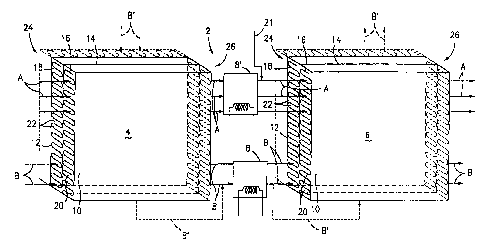
Referring now to the drawings, there is shown in FIG. 1 a schematic
view of a first embodiment of a fuel gas selective oxidizer assembly formed
in accordance with this invention. The selective oxidizer assembly is
denoted generally by the numeral 2 and includes a pair of spaced-apart
heat exchange zones 4 and 6, with a coolant heat exchanger $ interposed
between the two zones 4 and 6. The oxidizer assembly 2 is formed from
parallel outer planar wall members 10 and 12 sandwiched around, and
spaced-apart from a medial planar wall member 14. the wall members 10,
12 and 14 are separated from each other by corrugated core sheets 16 and
18. The planar sheets 10 and 14 combine with the corrugated sheet 16 to
form a plurality of gas flow passages 20 through which the reformer gas-
oxygen mixture flows. The planar sheets 12 and 14 combine with the'
corrugated sheet 18 to form a plurality of coolant flow passages 22.
!t will be noted that each of the gas flow passages 20 is paired with a
respective coolant flow passage 22, and that the passages 20 and 22 share
a common wall, i.e., the planar sheet 14. The embodiment shown in FIG. 1
is an embodiment of the invention which employs unidirectional flow of both
the coolant stream and the reformer gas-oxygen mixture stream. That is to
2o say, the fuel gas-oxygen mixture stream flows in the direction indicated by
arrows A, and the coolant stream flows in the same direction, as indicated
by arrows B. The ends of the assembly 2 denoted by the numeral 24 can be
characterized as inlet ends for the assembly zones 4 and 6; and the ends of
zones 4 and 6 of the assembly denoted by the numeral 26 can be
characterized as outlet ends of the assembly. It will be understood that the
gas mixture entering the passages 20 at the inlet ends 24 of the zones 4
and 6 of the assembly 2 comes from the fuel gas reformer and shift
converter components of the power plant, and the gas mixture leaving the
5
CA 02215062 1997-09-10
WO 97/25752 PCT/US97/0049I
passages 20 from the zone 6 is piped to the active area of the power plant
cell stack.
The assembly 2 operates as follows. Referring briefly to FIG. 3, the
walls 11 and 15 of the plates 10 and 14 respectively, as well as the surfaces
'
of. the corrugated sheet 16 which form the sides of the gas passages 20 in
the zones 4 and 6, are provided with a platinum catalyst coating 21 which is
capable of selectively oxidizing carbon monoxide (CO) in the reformer fuel
gas-oxygen mixture. The fuel gas-oxygen mixture, which may contain as
much as 1.0% {10,000 ppm) CO enters the inlet end 24 (shown in FIG. 1 ) of
to the fuel passages 20 at temperatures which are typically in the range of
about 220o F. to about 360o F.. The coolant stream enters the inlet end 24
(shown in FIG. 1 ) of the coolant passages 22 at temperatures in the range
of about 180o F. to about 360o F.. It is important to maintain the fuel gas
mixture at a temperature of not less than about 220o F. at the inlet end 24 of
15 the assemblage 2 so as to ensure that the catalyst in the fuel gas mixture
flow passages 20 is not rendered ineffective by the relatively large
percentage of CO in the gas mixture as it enters the oxidizer zone 4. The
threshold temperature for catalyst degradation is 220o F., however if the
temperature increases to greater than about 360o F. to about 380o F., the
2Q catalyst loses its selectivity, and the hydrogen in the reformed gas stream
will be burned, in lieu of the CO in the gas stream. The high heat transfer
provided by this assemblage with its increased catalyzed surfaces, and the
heat transfer fluid (either gas or liquid), maintains the reactant stream at
an
optimum temperature, even when there is a large quantity of heat generated
25 from oxidation of CO in the gas stream. The coolant and gas streams both
exit the first zone 4 of the assemblage at a temperature in the range of
about 220o F. to about 380o F..
At this point, the CO content of the reformer gas stream is typically in
the range of about 300-500 ppm. The coolant stream passes through the
3o coolant heat exchanger 8 where the temperature of the coolant stream is
lowered to about 170o F.. The 170o F. coolant stream enters the coolant
6
CA 02215062 1997-09-10
WO 97/25752 PCT/U597/00491
passages 22 at the entrance end 24 of the second zone 6 of the
assemblage 2, while at the same time the fuel gas stream is.cooled, if
necessary, to a temperature in the range of about 170o F. to about 220o F.
' in a fuel gas heat exchanger 8'. Additional oxygen may be added to the fuel
gas line via line 21. The re-oxygenated fuel gas then enters the gas stream
passages 22 at the entrance end 24~of the second zone 6 of the
assemblage 2. Flowing through the second zone fi of the assemblage 2,
the temperature of the reformer gas stream will be lowered to about 180o F.,
and the CO content of the reformer gas stream will be lowered to less than
to about 10 ppm. The reformer gas stream which exits the end 26 of the
assemblage zone 6 will thus have a temperature of about 180o F. and a CO
content of less than about 10 ppm. As shown in phantom lines in FIG. 1,
the coolant and fuel gas streams can be made to flow in cross directions as
noted by the arrows A~and B'.
FIG. 2 is a schematic view of a second embodiment of a selective
oxidizer which is formed in accordance with this invention. The assemblage
shown in FIG. 2 is denoted generally by the numeral 2' and includes a
housing 28 formed from the flat plate components as described above. The
coolant stream flows through the housing 28 in the direction of the arrows D
2o and the fuel gas-oxygen mixture stream flows through the housing 28 in the
direction of the arrows C. The coolant enters the end 30 of the housing 28
at a temperature which is less than about 220o F., and preferably in the
range of about 150o F. to about 170o F.. The fuel gas-oxygen mixture
stream enters the end 32 of the housing 28 at a temperature in the range of
about 220o F. to about 380o F.. The fuel gas stream exits the end 30 of the
housing 28 at a temperature in the range of about 180o F. to about 220o F.,
and the coolant stream exits the end 32 of the housing 28 at a temperature
in the range of about 220o F. to about 360o F..
The use of the plate construction with outer planar parts and inner
3o separate passages results in a lightweight, strong oxidizer assembly which
provides a large surface area per unit volume. The entire surface of the fuel
7
CA 02215062 1997-09-10
WO 97/25752 PCTlUS97100491
gas flow passages in the oxidizer heat exchanger assembly can be
catalyzed by Wash coating and selectively applying the catalyst to the fuel
gas flow passages in the assembled structure. The fact that the gas flow
and coolant flow sections of the assembly form extensive heat exchange
surfaces allows the assembly to be operated at more accurately controlled
temperatures than the currently available shell and tube catalyzed pellet -
type oxidizers. The gas and coolant passages have been shown in the
drawings as being formed from one or more corrugated sheets, however,
separate U-shaped strips could also be used instead. The weight and size
1o savings achieved by using the plate-type construction described above is
enhanced with larger higher power output fuel cell power plants.
Since many changes and variations of the disclosed embodiir~ent of
the invention may be made without departing from the inventive concept, it
is not intended to limit the invention other than as required by the appended
claims.
What is claimed is:
8