Note: Descriptions are shown in the official language in which they were submitted.
~ CA 0221~092 1997-09-08
PERFORATED FOOD CASINGS AND METHOD
TECHNICAL FIELD
The present invention relates to per rora~ed food casings and more
particularly to a food casing having die cut perforations and to a method of
forming the casing.
s
BACKGROUND OF THE INVENTION
Use of casings in the food processing industry is well known. One
segment of this industry uses casings in the production of food products
involving whole muscles or large chunks of meat. An example would be
smoked ham wherein the whole ham is stuffed into a casing for the smoking
operation. Another example is a so called chunk-and-formed product where
large meat chunks are combined for stuffing into a casing. For these types of
food products, it is desirable that the casing have a plurality of vent openingsin order to enhance or facilitate the expulsion of air from the casing as the large
I s meat mass is stuffed into the casing, and to enhance or facilitate the draining
of liquids such as water, meat juices and the like formed during or after
processing.
A common stuffing method for producing these types of food
products involves the use of flattened casing on reels and the stuffing
apparatus as described, for example, U.S. Patent No. 4,696,079. In this
apparatus, a measured length of casing is pulled from the reel. The end of the
casing is opened and a meat mass is rammed into the open casing. The open
end is gathered and clipped to close it. Then the casing on the opposite side
of the meat mass is gathered and the casing is pulled back from the clip closure~s so the casing wall is drawn up tightly around the meat mass thereby expelling
D-201 75
CA 0221~092 1997-09-08
- Page 2 -
entrapped air from between the casing and the meat mass. A second clip is
applied to close a second end of the casing and then the casing is cut to
separate the encased food product from the reel.
The speed and force of drawing the casing tight about the meat
mass necessitates a perforated casing to facilitate the venting of air and excess
liquids which may be squeezed from the meat mass as the casing tightens
around it. Thereafter, during processing such as by cooking or smoking,
additional gases and juices are released which are vented and drained from the
casing through the perforations.
The most collllllon method of providing the casing with vent holes
is to flatten the casing and then prick through both plies of the flattened casing
with sharp, pointed needles. If the casing is pricked from above, the
pel roralions created will have inwardly disposed flaps in the upper ply of casing
and outwardly disposed flaps in the bottom ply of the casing. The use of
pointed needles also makes the vent flaps in the upper ply slightly larger than
those in the bottom ply and all perforations may have somewhat jagged edges.
Due to the non-uniform configuration and size of the vent
openings in the upper and lower plies, the venting of air, water and meat juicesis not uniform about the circumference of the casing. The non-uniform venting
also is the result of the closing of the inwardly disposed flaps during stuffing.
This is because the pressure and meat mass tend to force these flaps outward
so as to close off the vent openings. On the other side of the casing, the
internal casing pressure forces the outwardly disposed flaps to remain open.
A further drawback of this casing is that the flaps produced by
needle piercing are somewhat jagged and these jagged edges provide points
of stress concentration where tearing can initiate when the casing is drawn tight
about the meat mass. It also is possible for moving elements of the stuffing
apparatus to snag on these flaps and initiate a tear or other casing failure.
D-201 75
~ CA 0221~092 1997-09-08
- Page 3 -
Various efforts have been made to improve perforated casing. For
example, U.S. Patent No. 3,779,284 discloses use of a flat faced punch to make
the vent opening. The punch is on a roller which interfaces with a backup roll
having a resilient surface. As the punch presses the casing into the resilient
surface, it tears a slug of casing from the upper and lower plies of casing and
deposits them in the resilient surface of the backup roll. Since the backup
surface is resilient, the lower ply still exhibited an outwardly flared edge caused
by the p~-ss~e of the punch. These flared edges still provide snag points and
areas of stress concentration where tears can initiate. Moreover, venting still
is not uniform around the casing perimeter and the backup roll has a relatively
short life due to the constant contact with the punches.
Other al~e,npts have been made to provide an improved
perforated casing by using knife points. However, slits produced with knife
points are not entirely satisfactory.
One drawback with prior art methods using pin or knife points to
form the vents, or using punches against a resilient backup roll to knock slugs
from the casing is that care had to be taken to avoid damaging the folded edge
of the laid flat casing. This is because a sharp pin, knife point or punch whichnicked the casing edge tended to produce a more ragged perforation in this
area so the casing was more susceptible to tearing when drawn up tight against
the meat mass. For this reason, care was taken to insure that the perforating
apparatus did not operate out to or beyond the folded edge of the laid flat
casing. This required a change in the set up of the apparatus for each differentflat width of casing.
Accordingly, there is a need for pe, roraled casing having improved
venting properties and for methods and apparatus for making such a casing.
D-201 75
~ CA 0221S092 1997-09-08
- Page 4 -
OBJECTS OF THE INVENTION
One object of the present invention is to provide a tubular food
casing having vent openings substantially free of inwardly and outwardly
disposed flaps.
s Another object of the present invention is to provide a food casing
having a vent rate of air and liquids which is uniform around the casing
perimeter.
A further object of the present invention is to provide a vented
food casing wherein the vent openings are formed by die cutting such that the
edges defining the openings are substantially clean cut and are flush with the
casing wall.
Yet another object is to provide a method for obtaining a
perforated casing having vent openings which are uniform and clean cut and
which have no inwardly or outwardly disposed flaps or lips or the like.
SUMMARY OF THE INVENTION
In accordance with the present invention, a casing article is
provided for use in stuffing whole muscle meat and chunk-and-formed meat
products having enhanced venting of air and liquids such as water, meat juices
and the like. The enhanced venting results from die cut vent openings wherein
the die cutting physically removes casing material to provide a substantially
clean cut edge which is flush with the wall of the casing. Moreover, the vent
openings are die cut with the casing in a laid-flat condition so openings on both
sides of the casing are in registration, are of equal area and have edges which
align All of these features contribute to provide a vent rate through
diametrically opposite areas of the casing which is substantially constant.
The die cut method according to the present invention utilizes
both male and female die cutting members so the openings have a relatively
D-201 75
~ CA 0221~092 1997-09-08
- Page 5 -
s",oolh clean edge free of stress concentration points. Consequently, there is
no danger of weakening the casing by providing vent openings even at the
casing edge. This simplifies production in that no special adjustment need be
made when perforating casings of different flat widths. The die cutting
members are in the form of rollers with punches on a first roller and die
openings on a second roller. Except for the meshing of the punches and die
openings, the rollers are not geared together or motor driven. Instead, the
drawing of the casing between the rollers and against the punches drives the
first roller and the meshing of the punches with the die openings drives the
l O second roller.
It is important for the rotation of the two rollers to be synchronized
so that each punch mates with only one given die opening. To accomplish this,
the punches and the associated die openings are staggered about the roller
peri~heries so that at a given increment of rotation there is at least one punchIS fully inserted in its counterpart die opening and several more punches which
are at dirrerent stages of insertion and retreat. In this fashion, the second roller
is continuously driven in synchronism with the first roller by the progressive
insertion of punches into their counterpart die openings and subsequent retreat
of the punches from the die openings.
The die cutting operation removes a slug of casing to form a
clean-cut opening having a smooth edge which is generally flush with the
casing wall. That is, there are little or no portions of the casing such as a lip,
flap or shred about the openings which extend outward or inward with respect
to the plane of the casing wall.
'~5 The slugs of casing or ~chad~ are forced progressively down the
die opening and into the interior of the second roller which is hollow. The chadis then removed from the hollow interior by any suitable means such as by a
vacuum line communicating with the hollow interior.
D-201 75
~ CA 0221~092 1997-09-08
- Page 6 -
DESCRIPTION OF THE DRAWINGS
Figure 1 is perspective view showing the casing of the present
invention laid flat;
Figure 2 is an enlarged view of a portion of the Figure 1 casing
partly broken away and in sections;
Figure 3 is a schematic view illustrating apparatus and a method
for making the casing of the present invention;
Figure 4 is a schematic view on an enlarged scale showing a
portion of the apparatus for die cutting the casing and practicing the method ofthe present invention; and
Figure 5 is a schematic view illustrating the progression of die
openings along the surface of the die cutting apparatus.
DETAILED DESCRIPTION OF THE INVENTION
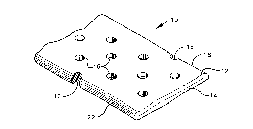
Referring to the drawings, Figure 1 shows the casing of the
present invention generally indicated at 10. The casing is tubular but is shown
flattened in Figure 1 so that two plies 12 and 14 of the casing are laid flat one
against the other. The plies each represent one-half of the casing perimeter so
the flat width of the casing is one-half its circumference. The casing preferably
is of regenerated cellulose but it could be of any other well known food casing
material such as a plastic casing, for example, nylon or a multilayer film. Mostpreferably, the casing is a fibrous casing which is a regenerated cellulose
casing having a reinforcing web of a nonwoven paper. Fibrous casings are well
known in the art.
The casing is pe,r~rated by a plurality of die-cut vent openings 16.
These openings preferably are circular or oval so there are no stress
concentration points as would be produced by sharp corners of square or
rectangular openings. Die cut openings are produced by removing plugs or
D-201 75
~ CA 0221~092 1997-09-08
- Page 7 -
slugs of the casing material to provide openings 16. These openings 16 may
vary in size from 0.015 to 0.040 inches (0.38 to 1.02 mm) in diameter and
extend over the surface of the laid flat casing in a predetermined defined
pattern. As shown in Figure 1, it is possible for the die cut operation, as
described further hereinbelow, to cut openings 16 out to and including the
edges 18, 22 of the laid flat casing.
The die cut openings 16 have relatively clean edges in that they
are free of flaps, flanges or the like which extend inward or outward from the
casing surfaces. This is best seen in Figure 2.
Io As shown in Figure 2, the laid flat plies of casing 12, 14 of Figure
1 are shown separated for purposes of illustration. The die cut vent openings
16 (a) in upper ply 12 and the openings 16 (b) in lower ply 14 each have
relatively clean cut edges 24. Further, the edges of the openings are
substantially flush with the plane of the casing and there is no portion of the
I S casing wall about the openings which extends outward from the outer surface26 of the casing wall or inward from the inner surface 28 of the casing wall.
Moreover, since both the openings 16 (a), 16 (b) are formed by a
single combination of male and female die cut members, as set out
hereinbelow, there is a registration of the openings including an alignment of
the edges 24 and they have substantially the same open area. It should be
appreciated that given the small size of the die cut openings 16 and the nature
of the cellulosic material of the casing, some fraying of the edges can occur
depending upon various manufacturing parameters and as the punches and
dies wear through use.
2s The apparatus for die cutting the vent openings is shown in Figure
3. The apparatus includes a roller 30 which is mounted for rotation about an
axis 32. Roller 30 has a plurality of punches 34 extending from its surface. Theroller and punches comprise the male member of a die cutting set. The second
D-201 75
~ CA 0221~092 1997-09-08
- Page 8 -
member of the set also is a roller 36, mounted for rotation about an axis 38
which is parallel to axis 32. The roller 36 is provided with a plurality of die cut
openings (not shown) arranged for receiving the punches 34. Roller 36 and its
die openings comprise the female member of the die set. As further set out
hereinbelow, the arrangement of the punch and die openings is such that each
punch 34 mates with only one given die cut opening.
The surface 40 of roller 36 is rigid and the two rollers are spaced
apart so the space between them is greater than the thickness of the flattened
casing.
I 0 The flattened casing which passes between the two rollers 30, 36is die cut by the operation of punches 34 on roller 30 mating with the die
openings on roller 36. In this respect, an unpunctured laid flat casing 41 is
drawn from a supply reel 42 and between the two rollers 30, 36. The casing is
pe,rorated as it passes between the rollers and the casing, now perforated, is
l 5 taken up by a rewind reel 44. Idler rolls 46 are optionally disposed to press and
partly wrap the casing around female roller 36. With this arrangement, the
female roller 36 is driven by the casing as the casing is pulled through the
space between the rollers.
Preferably, the rewind reel 44 is driven for pulling the casing from
the supply, or unwind, reel 42 and drawing the casing between the set of die cutrollers 30, 36. The two rollers 30, 36 are not themselves driven by an
independent drive. Also, gears for interconnecting the two rollers 30, 36 and
driving them in synchronism are optional. The driving of both the die cut rollers
preferably is accomplished simply by advancing the casing between the rollers.
For example, if the casing is drawn straight through the gap
between the rollers, the casing first engages punches 34 and this causes the
rotation of the first male roller 30 about its axis 32. As the roller 30 turns, the
punches 34 first press plies of casing against the rigid surface of the female
D-20175
~ CA 0221~092 1997-09-08
- Page 9 -
roller 36 and then drive through the casing and into its mating die opening 48
as shown in Figure 4. The mating or meshing of the punches 34 and die
openings 48 serve as the drive for rotating the female roller 36.
In a preferred embodiment7 as shown in Figure 3, where the
S casing is partly wrapped around the second roller 36, advancing the casing will
drive the second roller. This in turn causes the rotation of the first roller.
In any event, as each punch mates with its associated die cut
opening 48 in roller 36, a slug or plug 50 is die cut from both plies of casing.The female roller 36 has a hollow interior. Accordingly, as shown in Figure 4,
l O the plugs 50 of casing, otherwise known as "chad", work down the die opening
48 and into the hollow interior 52 of the female die member. From here the
chad is removed by any suitable means, such as a vacuum line (not shown)
connected to the hollow interior of roller 36.
The punches 34 and die openings 48 are arranged so there is a
progressive engagement of punches into their associated die openings and this
keeps the rollers moving in synchronism. This is illustrated in Figure 5.
Figure 5 shows a portion of the surface of the second roller 36
with the direction of rotation indicated by arrow 56.
As seen in Figure 5, the die openings 48 (and therefore the
associated punches on roller 30) are arranged in columns which are equally
spaced across the width of the second roller. Each column (numbers 1-21)
contains the same number of die openings equally spaced about the periphery
of the second roller. Further, the die openings 48b (and their associated
punches) in the second column (2) are offset from the die opening 48a in the
first column. The offset can be either leading or trailing in the direction of
rotation as indicated by arrow 56. If the offset leads in the direction of rotation,
the amount of the offset is slightly more than one-half the arc length between
the equally spaced die openings. If the offset trails or lags in the direction of
D-20175
~ CA 0221~092 1997-09-08
- Page 10 -
rotation the amount of offset is slightly less than the arc length between the
equally spaced die openings. The openings 48c (and their associated
punches) in the third column (3) are offset a like amount from the die openings
48b in the second column. The offset of the die opening in one column from
S those in an adjacent column continues across the roller for each successivecolumn of die openings. With this arrangement, the offset from one column to
the next is n/2 plus or minus a small increment of arc (say 1 ~) where "n" is the
number of degrees between the die openings in a column.
Offsetting one column of die openings from another slightly more
or less than one-half the arc length between die openings, is important to the
synchrononous driving of the rollers. For example, if the offset was simply 1~
of arc, then the progression of punches into full engagement with their
respective die openings would progress straight across the width of the rollers
from column 1 to column 21. However, with the offset being n/2 + 1~ or n/2 - 1~
IS the progressive enyagelllent of punches into the die openings across the width
of the rollers is scattered between the columns and this results in a smoother
meshing and synchronous driving of the rollers. For example, given a
distribution of die openings as shown in Figure 5, an offset of n/2 + 1~ and a
spacing between die openings of 20~, then the line 54 represents an instant in
the rotation of the rollers where only the punches corresponding to the
openings 48 in columns 1 and 21 would be centered and fully engaged with
these die openings. However, scattered along line 54 are punches in various
stages of advancement into the die openings and others in various stages of
retreat from the die openings relative to the time at line 54. In particular, and
2s as shown in Figure 5, punches associated with die openings in columns 12, 3,
14, 5, 16, 7, 18, 9, 20, and 11 would be respectively 1~, 2~, 3~, 4~, 5~, 6~, 7~,
8~, 9~ and 10~ of arc past full engagement and in retreat from the die openings.On the other hand, punches associated with die openings in columns 10, 19,
D-201 75
~ CA 0221~092 1997-09-08
- Page 11 -
8, 17, 6, 15, 4, 13 and 2 would be respectively 1~, 2~, 3~, 4~, 5~, 6~, 7~, 8~ and
9~ of arc away from full engagement with their associated die openings.
Thus, not all the punches across the roller are fully engaged with
a corresponding die opening at any given instant of rotation. The arrangement
as shown, provides a continuous progression around the rollers so that each
degree of rotation brings at least one punch into full engagement with its
associated die opening and there is a continuous driving of the second roller
36 by the first roller 30. However, the action of punches entering and leaving
their mating die openings is not in a prugression from column to column straightacross the width of the rollers. Instead the progression of punches which are
fully inserted into a die opening alternates back and forth from one column to
another across the width of the roller. For example, in the Figure S
embodiment, the progression of punches from time line 54 which are fully
inserted into a die opening would be in the following column order: 10, 19, 8,
17, 6, 15, 4, 13, 2, 11, 20, 9, 18, 7, 16, 5, 14, 3, 12 and then 1 and 21
simultaneously. Accordingly, the location of a punch which is fully inserted into
a die opening moves back and forth between columns which are not adjacent
so the progression is not linear across the rollers. It is this arrangement which
maintains a synchronous rotation of the two rollers 30 and 36. While no gears
are needed for this synchronous rotation, it is important that the rollers be
secured in a suitable frame (not shown) which maintains the axis of rotation of
each member parallel and at a fixed distance apart. Means for such securing
are well within the skill of the art.
To demonstrate the present invention, rollers 30 and 36 were
made. The female roller 36 had a diameter of about 3.25 inches (8.25 cm) and
was 12.5 inches (31.75 cm) long. The roller was hollow and its surface 40 was
a hardened steel. The roller was provided with 378 of the die cutting openings
48 arranged in 21 columns with 18 openings in each column. The columns
D-201 75
CA 0221',092 1997-09-08
- Page 12 -
were about one-half inch (12.7 mm) apart and the die openings in each column
were spaced about 20~ apart. As noted above, the openings in one column
were offset about 11 ~ (or n/2 + 1 ~) from the openings in an adjacent column.
The die openings were each about 0.028 (0.71 mm) inch in diameter and each
opening communicated with the hollow interior of the roller.
Male roller 30 was provided with 378 punches similarly arranged.
The punches projected about 0.120 inches (3.05 mm) from the surface of the
roller and the effective diameter of the roller, including punch length, was about
equal to the diameter of the female roller 36.
Io The punches were of a softer steel than the surface of roller 36
and had a hardness of about 25-30 Rc. The punches were formed with a
diameter slightly larger than the diameter of the die openings. During the
maiden engagement, the punches were sheared upon entering the die
openings and in this way each punch was sized to fit closely into its associateddie opening.
For operation, the rollers were set about 0.115 inches (2.92 mm)
apart so that the depth of punch penetration into the die openings was about
0.005 inches (0.13 mm). It should be appreciated that the number of punches
and penetration depth as noted above, clearly can vary depending upon the
selected diameter of the roller and the desired number and length of the
punches.
The frame holding the rollers must be sufficient to maintain an
alignment of the two rollers to insure a proper mating of each pin and its
associated die opening. As noted above, it is this alignment together with the
~5 progressive entry and removal of punches into the die openings which drivesthe female roller 36 and keeps the two rollers rotating in synchronism.
A Viskase Corporation size 11 fibrous casing (8.25 inches or
20.95 cm flatwidth) was run through the die punch apparatus at a speed of
D-20175
CA 0221~092 1997-09-08
- Page 13 -
about 200 feeVmin (60.96 m/min). No special care was taken to position the flat
stock to insure that the casing edges were outside of the die cut area.
Accordingly, the perforated casing did exhibit die cut openings at intervals
along the casing edge.
The die cut casing contained die cut vent openings arranged in
a hexagonal pattern which mirrored the array shown in Figure 5, the openings
in the machine direction (columns) being about 0.56 inch (14.22 mm) apart and
in the transverse direction (rows) being about one-half inch (12.2 mm) apart.
This produced about 3.5 openings per square inch and on inspection it was
determined that over 95% of the die cut openings were free of casing material.
A test was devised to delen"i"e the vent rate of the casing. In this
respect one end of the casing is gathered and closed. The casing is oriented
vertically with its closed end down and open end up. Water is poured into the
casing. The rate of the inflow is controlled to just keep the casing filled while
avoiding an overflow from the open top. In this fashion, the rate of inflow
balances and is equal to the vent rate through the casing wall. With the casing
formed as noted above, it was de~ei " ,ined that the vent rate of a casing section
about 12 inches (30.48 cm) long was 10.8 gals (40.8 liters) per minute. In
contrast, a similar size fibrous casing made in the conventional manner using
0.060 in. (1.52 mm) diameter presticking pins arranged in essentially the same
pattern had a vent rate of only 6.4 gal/min (24.21 liters). Thus, the inventive
casing, with die cut openings of only 0.028 inches (0.71 mm) in diameter had
a greater vent rate than the same size casing prestuck with needles of more
than twice the diameter.
The draining of the water from about the casing parameter was
observed. It was evident that for the inventive casing, the flow rate appeared
uniform from around the casing. However, for the prestuck casing formed using
presticking pins, it was evident that there was a greater flow from one side of
D-201 75
. CA 0221~092 1997-09-08
- Page 14 -
the casing than from the other . Thus, the vent rate of the casing of the present
invention was both greater than that of the casing stuck with a larger diameter
pin and more uniform around the casing. These features are highly desirable.
The higher vent rate allows the rapid venting of air during
stuffing. This permits a faster operation and decreases the likelihood of
bursting the casing as it is drawn up tight about the food product. The smaller
openings and uniformity of venting contributes to the appearance of the food
product as further noted below.
The casings were stuffed and processed to produce a chunk-and-
l o form ham product. The stuffed samples were visually inspected after
processing. Product formed in the casing of the present invention had a
uniform distribution of "nubs" on the product surface. These nubs are formed
by meat juices which exude through the vent openings and coagulate under
p~ucessi~lg conditions. In cont~csl, the conventionally prestuck casing was lessl 5 uniform in appea,dnce because the nubs at one side of the stuffed casing were
more prominent than those at the opposite side of the casing.
Thus, it should be appreciated that the present invention provides
a pe, roraled casing having improved venting properties. The improved venting,
as provided by the die cut openings, increases the rate of venting over larger
vent openings made by needle presticking and provides for a more uniform
venting about the casing periphery for enhancement of product appearance.
Having described the invention in detail what is claimed as new
is:
D-201 75