Language selection

Search

Patent 2215577 Summary

Third-party information liability

Some of the information on this Web page has been provided by external sources. The Government of Canada is not responsible for the accuracy, reliability or currency of the information supplied by external sources. Users wishing to rely upon this information should consult directly with the source of the information. Content provided by external sources is not subject to official languages, privacy and accessibility requirements.

Claims and Abstract availability

Any discrepancies in the text and image of the Claims and Abstract are due to differing posting times. Text of the Claims and Abstract are posted:

  • At the time the application is open to public inspection;
  • At the time of issue of the patent (grant).
(12) Patent Application: (11) CA 2215577
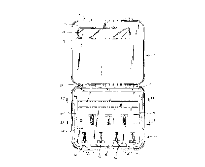
(54) English Title: ROUTER BIT CASE
(54) French Title: COFFRET POUR MECHES DE TOUPIE
Status: Deemed Abandoned and Beyond the Period of Reinstatement - Pending Response to Notice of Disregarded Communication
Bibliographic Data
(51) International Patent Classification (IPC):
  • B25H 3/02 (2006.01)
  • B25H 3/00 (2006.01)
(72) Inventors :
  • HADDOCK, GROVER C. (United States of America)
  • KHERADPIR, KAMYAR (United States of America)
  • SIMON, PAUL J. (United States of America)
  • VONHOENE, CLIFF J. (United States of America)
(73) Owners :
  • VERMONT AMERICAN CORPORATION
(71) Applicants :
  • VERMONT AMERICAN CORPORATION (United States of America)
(74) Agent: BORDEN LADNER GERVAIS LLP
(74) Associate agent:
(45) Issued:
(22) Filed Date: 1997-10-01
(41) Open to Public Inspection: 1998-04-08
Availability of licence: N/A
Dedicated to the Public: N/A
(25) Language of filing: English

Patent Cooperation Treaty (PCT): No

(30) Application Priority Data:
Application No. Country/Territory Date
08/727,734 (United States of America) 1996-10-08

Abstracts

English Abstract


The invention is directed towards a storage case formed
from an upper shell, a lower shell and an insertable tray.
The insertable tray is removably positioned in an opening in
the lower shell. The insertable tray contains supports for
tools and parts such as router bits. When the upper shell,
lower shell and insertable tray are joined a convenient
storage case is formed. Alternatively, the insertable tray
can be detached from the lower shell and used to store the
tools and parts in a readily accessible manner.


French Abstract

L'invention porte sur un coffret composé d'une coque supérieure, d'une coque inférieure et d'un plateau insérable qui est placé de façon non permanente dans une ouverture de la coque inférieure. Le plateau comprend des supports pour outils et pièces, tels que des mèches de toupie. Lorsque les deux coques et le plateau sont fixés les uns aux autres, ils forment un coffret pratique. Toutefois, il est possible de détacher le plateau de la coque inférieure et de l'utiliser pour ranger les outils et les pièces d'une manière facilement accessible.

Claims

Note: Claims are shown in the official language in which they were submitted.

WHAT IS CLAIMED IS:
1. A storage case comprising:
an upper shell and a lower shell hinged to each other at
respective first ends;
an insertable tray removably positioned in an opening in
the lower shell; and
the insertable tray forming at least a portion of an
outer external surface of the storage case.
2. The storage case of claim 1 further comprising:
an upper surface of the insertable tray contacting the
lower shell at or adjacent to a first end of the insertable
tray;
a lower surface of the insertable tray contacting the
lower shell at or adjacent to a second opposite end of the
insertable tray; and
tray retaining members attached to the lower shell
contacting the insertable tray at or adjacent to the second
opposite end.
3. The storage case of claim 1 further comprising:
the insertable tray comprised of at least one support for
supporting objects to be stored.
4. The storage case of claim 3 further comprising:
the insertable tray further comprised of at least one
projection located in an at least one corresponding groove in
the lower shell; and
an aperture configured to enable mounting of the
insertable tray formed in the at least one projection.

5. The storage case of claim 3 further comprising:
the at least one support comprising:
at least one vertical rod support;
a plurality of raised horizontal rod supports; and
at least one set of parallel rail supports.
6. The storage case of claim 1 further comprising:
a window opening in the upper shell for viewing the
contents of the storage case.
7. A storage case comprising:
an upper shell and a lower shell rotationally attached to
each other;
an insertable tray removably positioned in an opening in
the lower shell;
an upper surface of the insertable tray contacting the
lower shell;
a lower surface of tile insertable tray contacting the
lower shell;
tray retaining elements attached to the lower shell for
biasing the insertable tray against the lower shell;
the insertable tray forming at least a portion of an
outer external surface of the storage case.
8. The storage case of claim 7 further wherein:
the upper surface of the insertable tray located at or
adjacent to a first end of the insertable tray contacting the
lower shell;

a portion of the lower surface of the insertable tray
located at or adjacent to a second opposite end of the
insertable tray contacting the lower shell;
the tray retaining elements contacting the insertable
tray at or adjacent to the second opposite end.
9. The storage case of claim 7 further comprising:
the insertable tray comprised of:
at least one support for supporting objects to be
stored;
at least one projection; and
a stepped edge forming at least a portion of an edge of
the insertable tray.
10. The storage case of claim 9 further wherein:
the at least one projection of the insertable tray
located in an at least one corresponding groove in the lower
shell;
the stepped edge portion of the insertable tray
contacting the lower shell.
11. The storage case of claim 10 further wherein:
a bottom surface of he stepped edge portion of the
insertable tray contacting the lower shell.
12. The storage case of claim 9 further comprising:
the at least one support comprising:
at least one vertical rod support;
a plurality of raised horizontal rod supports;
at least one set of parallel rail supports.

13. The storage case of claim 12 further wherein:
the objects to be stored are router bits.
14. The storage case of claim 7 further comprising:
a window opening in the upper shell for viewing the
contents of the storage case.
15. The storage case of claim 9 further comprising:
an aperture in the at least one projection configured to
enable mounting of the insertable tray.

Description

Note: Descriptions are shown in the official language in which they were submitted.


CA 0221~77 1997-10-01
ROUTER BIT CASE
'R~0~2~D OF THE lNV~;NllON
The present invention is directed to a storage case for
tools and/or parts such as router bits. More particularly,
the present invention is directed to a storage case which
provides for both convenient transportation and storage of
tools and parts as well as the ability to hang up or mount the
tools and/or parts for improved access.
Storage cases are commonly formed with internal
permanently attached trays in which the tools and/or parts are
stored. A problem associated with storage cases utilizing
internal permanently attached trays is the difficulty of
retrieving and returning tools and/or parts from the trays.
Each time a tool and/or part needs to be retrieved the storage
case must be opened and the correct tray accessed. This is
timely and requires the reservation of valuable work space to
enable the opening of the storage case, particularly when
multiple storage cases are utilized simultaneously.
The object of the present invention is to provide a
storage case that provides storage for multiple tools and/or
parts and further provides the advantages of improved access
for the retrieval and return of tools and/or parts and
eliminates the need to reserve valuable work space.
S~MMARY OF THE INVENTION
According to the present invention there is provided a
storage case that comprises an upper shell and a lower shell
hinged to each other and an insertable tray ~e,..ovdbly
positioned in an opening in the lower shell. When the upper
shell, lower shell and the insertable tray are joined they

~ CA 0221~77 1997-10-01
form a convenient carrying storage case. Alternatively, the
insertable tray may be detached from the lower shell and used
independently to mount and store tools and/or parts in a
reduced space with improved accessibility.
The insertable tray and lower shell are shaped in order
to enable the insertable tray to be removably positioned in
the opening of the lower shell. The insertable tray is
removably positioned in the opening by first sliding it into
the opening of the lower shell and second securing it using
retaining elements attached to the lower shell.
As pointed out in greater detail below the storage case
of the present invention provides the important advantages of
an improved access to tools and/or parts and the reduction of
the space required for storage and access during periods of
use.
The invention itself, together with further objects and
attendant advantages, will best be understood by reference to
the following detailed description taken in conjunction with
the accompanying drawings.
BRIEF DESCRIPTION OF THE DRAWINGS
FIG. 1 illustrates a top view of the storage case in a
closed position.
FIG. 2 illustrates a bottom view of the storage case of
the present invention in a closed position.
FIG. 3 illustrates a back view of the storage case in a
closed position.
FIG. 4 illustrates a front view of the storage case in a
closed position.

CA 0221~77 1997-10-01
FIG. 5 illustrates a right side view of the storage case
in a closed position.
FIG. 6 illustrates a cutaway view of the storage case
taken at line 6--6 including exploded views of the preferred
case closure elements and hinge extensions.
FIG. 7 illustrates a top view of the upper shell.
FIG. 8 illustrates a bottom view of the upper shell.
FIG. 9 illustrates a top view of the lower shell with the
insertable tray removed.
FIG. 10 illustrates the storage case in an open position.
FIG. 11 illustrates a cutaway view of the storage case
taken at line 11--11.
FIG. 12 illustrates a cutaway view of the storage case
taken at line 12--12.
FIG. 13 illustrates a top view of the insertable tray.
FIG. 14 illustrates a top view of the insertable tray
with stored router bits.
DESCRIPTION OF THE PREFERRED EMBODIMENTS
Turning now to the drawings, Fig. 1 shows the storage
case 20 of the present invention. An upper shell 22 forms the
top half of the storage case 20. The upper shell 22
optionally may include a window opening 24 for viewing the
contents of the storage case.
As illustrated in Fig. 2, a lower shell 26 forms the
bottom half of the storage case. The lower shell 26 includes
an opening 28 in which is removably positioned an insertable
tray 30. The insertable tray 30 forms a substantial portion
of the outer external surface 32 of the storage case. The
insertable tray 30 has at least one projection 34 extending

CA 0221~77 1997-10-01
outwards. The projections 34 are formed with apertures 36
configured to allow the storage case 20 as a whole or the
insertable tray 30 alone to be mounted on a wall or other
vertical surface (not shown). Mounting of the insertable tray
30 independently of the storage case 20 provides for improved
access to the stored objects and a decrease in the space taken
up during storage.
As shown in Figs. 3, 4 and 5, the upper shell 22 and the
lower shell 26 are rotationally attached to each other using
hinges 38 and are maintained in a closed position by closure
elements 40 attached to the lower shell 26 and by closure
elements 41 attached to the upper shell 22. Fig. 6 shows the
hinges 38 and closure elements 40,41 of the preferred
embodiment.
The upper shell 22, as shown in Figs. 7 and 8, optionally
includes a window pane 42 retained against the window opening
24 by window pane retaining elements 44 attached to the upper
shell 22.
Fig. 9 illustrates the lower shell 26 with the insertable
tray 30 removed. Located at a first end 46 of the lower shell
opening 28 are grooves 48 configured to receive the
projections 34 of the insertable tray 30. The lower shell 26
further includes a stepped edge 50 at the first end 46 of the
lower shell opening 28. Retaining members 52 are attached to
the lower shell 26 at a second opposite end 54 of the lower
shell opening 28. The retaining members 52 are used to retain
the insertable tray 30 within the lower shell opening 28.
Fig. 10 illustrates the storage case 20 in an open
position with the upper shell 22 and lower shell 26 pivoted

CA 0221~77 1997-10-01
around the hinges 38. The insertable tray 30 is shown
positioned in the lower shell opening 28.
Referring to Figs. 11 and 12, the insertable tray 30 has
a stepped edge 56 formed around a portion of its edge. The
bottom surface 58 of the stepped edge 56 contacts the lower
shell 26. Fig. 13 shows the placement of the projections 34
at a first end 60 of the insertable tray 30. The projections
34 fit in the corresponding grooves 48 of the lower shell 26
with the upper surfaces 62 of the projections 34 contacting
the lower shell 26. At a second opposite end 64 of the
insertable tray 30 there are notches 66 configured to receive
the corresponding retaining members 52 of the lower shell 26.
The insertable tray 30 is removably positioned in the
lower shell opening 28, by first sliding the insertable tray
30 into the lower shell opening 28 placing the projections 34
into the corresponding grooves 48 of the lower shell 24 and
second securing the insertable tray 30 in position by pushing
down on the second end 64 of the insertable tray 30 thereby
engaging the retaining members 52 into the corresponding
notches 66 in the insertable tray 30. The retaining members
52 bias the insertable tray 30 against the lower shell 26.
As illustrated in Figs. 11-14 the insertable tray 30
includes at least one support 68 for holding the objects to be
stored. The supports 68 of the preferred embodiment are
designed to store router bits 70. The supports 68 include a
vertical rod support 72, a plurality of raised horizontal rod
supports 74, plural tool supporting parallel rails 76 and
singular tool supporting parallel rails 78. It is envisioned
that numerous alternative supports could be utilized to store
a variety of objects.

CA 0221~77 1997-10-01
Of course, it should be understood that a wide range of
changes and modifications can be made to the preferred
embodiment described above. It is therefore intended that the
foregoing detailed description be understood that it is the
following claims, including all equivalents, which are
intended to define the scope of this invention.

Representative Drawing
A single figure which represents the drawing illustrating the invention.
Administrative Status

2024-08-01:As part of the Next Generation Patents (NGP) transition, the Canadian Patents Database (CPD) now contains a more detailed Event History, which replicates the Event Log of our new back-office solution.

Please note that "Inactive:" events refers to events no longer in use in our new back-office solution.

For a clearer understanding of the status of the application/patent presented on this page, the site Disclaimer , as well as the definitions for Patent , Event History , Maintenance Fee  and Payment History  should be consulted.

Event History

Description Date
Inactive: IPC from MCD 2006-03-12
Time Limit for Reversal Expired 2002-10-01
Application Not Reinstated by Deadline 2002-10-01
Deemed Abandoned - Failure to Respond to Maintenance Fee Notice 2001-10-01
Inactive: First IPC assigned 2000-10-25
Inactive: IPC removed 2000-10-25
Application Published (Open to Public Inspection) 1998-04-08
Inactive: Single transfer 1998-01-13
Classification Modified 1997-12-04
Inactive: IPC assigned 1997-12-04
Inactive: First IPC assigned 1997-12-04
Filing Requirements Determined Compliant 1997-11-21
Inactive: Filing certificate - No RFE (English) 1997-11-21
Inactive: Courtesy letter - Evidence 1997-11-20
Application Received - Regular National 1997-11-19
Inactive: Applicant deleted 1997-11-19

Abandonment History

Abandonment Date Reason Reinstatement Date
2001-10-01

Maintenance Fee

The last payment was received on 2000-08-25

Note : If the full payment has not been received on or before the date indicated, a further fee may be required which may be one of the following

  • the reinstatement fee;
  • the late payment fee; or
  • additional fee to reverse deemed expiry.

Please refer to the CIPO Patent Fees web page to see all current fee amounts.

Fee History

Fee Type Anniversary Year Due Date Paid Date
Application fee - standard 1997-10-01
Registration of a document 1997-10-01
Registration of a document 1998-01-13
MF (application, 2nd anniv.) - standard 02 1999-10-01 1999-09-30
MF (application, 3rd anniv.) - standard 03 2000-10-02 2000-08-25
Owners on Record

Note: Records showing the ownership history in alphabetical order.

Current Owners on Record
VERMONT AMERICAN CORPORATION
Past Owners on Record
CLIFF J. VONHOENE
GROVER C. HADDOCK
KAMYAR KHERADPIR
PAUL J. SIMON
Past Owners that do not appear in the "Owners on Record" listing will appear in other documentation within the application.
Documents

To view selected files, please enter reCAPTCHA code :


To view images, click a link in the Document Description column. To download the documents, select one or more checkboxes in the first column and then click the "Download Selected in PDF format (Zip Archive)" or the "Download Selected as Single PDF" button.

List of published and non-published patent-specific documents on the CPD .

If you have any difficulty accessing content, you can call the Client Service Centre at 1-866-997-1936 or send them an e-mail at CIPO Client Service Centre.


Document
Description 
Date
(yyyy-mm-dd) 
Number of pages   Size of Image (KB) 
Representative drawing 1998-04-22 1 12
Abstract 1997-10-01 1 14
Description 1997-10-01 6 186
Drawings 1997-10-01 10 178
Claims 1997-10-01 4 87
Cover Page 1998-04-22 1 45
Filing Certificate (English) 1997-11-21 1 164
Courtesy - Certificate of registration (related document(s)) 1998-05-05 1 117
Courtesy - Certificate of registration (related document(s)) 1998-05-05 1 116
Reminder of maintenance fee due 1999-06-02 1 112
Courtesy - Abandonment Letter (Maintenance Fee) 2001-10-29 1 183
Reminder - Request for Examination 2002-06-04 1 118
Correspondence 1997-11-20 1 28