Language selection

Search

Patent 2215689 Summary

Third-party information liability

Some of the information on this Web page has been provided by external sources. The Government of Canada is not responsible for the accuracy, reliability or currency of the information supplied by external sources. Users wishing to rely upon this information should consult directly with the source of the information. Content provided by external sources is not subject to official languages, privacy and accessibility requirements.

Claims and Abstract availability

Any discrepancies in the text and image of the Claims and Abstract are due to differing posting times. Text of the Claims and Abstract are posted:

  • At the time the application is open to public inspection;
  • At the time of issue of the patent (grant).
(12) Patent Application: (11) CA 2215689
(54) English Title: PUTTER WITH CONVEX STRIKING SURFACE
(54) French Title: FER DROIT AVEC SURFACE DE FRAPPE CONVEXE
Status: Deemed Abandoned and Beyond the Period of Reinstatement - Pending Response to Notice of Disregarded Communication
Bibliographic Data
Abstracts

English Abstract


A golf putter for striking a golf ball on a putting surface has an elongate
shaft with
a top end for gripping by a user, and a putter head at the opposed bottom end
with a front
face for striking the golf ball. The front face has a convex horizontal
curvature and a flat
vertical profile so that the golf ball is urged to travel in a desired
direction and so that a
forward roll is imparted thereon with minimal skidding of the golf ball on the
putting
surface. The putter head's top surface has a marker for aligning the golf ball
with the front
face. The marker is located at the apex of the convex horizontal curvature and
aligned
with the longitudinal axis of the shaft so that the golf ball travels in the
desired direction
even if the putter head is twisted slightly upon striking the golf ball.


Claims

Note: Claims are shown in the official language in which they were submitted.

THE EMBODIMENTS OF THE INVENTION IN WHICH AN EXCLUSIVE
PROPERTY OR PRIVILEGE IS CLAIMED ARE DEFINED AS FOLLOWS:
1. A golf putter comprising:
an elongate shaft having a hand gripping end;
a putter head connected to the shaft opposite said hand gripping end, said
putter
head comprising a front face for striking a golf ball, said front face having
a outwardly
curved surface in a longitudinal plane and a flat surface in a transverse
plane so that upon
striking the golf ball on a putting surface with said front face the golf ball
is urged to travel
in a desired direction, and a forward roll is imparted to the golf ball with
reduced skidding
effect.
2. The golf putter of claim 1 wherein said putter head further comprises top
and
bottom surfaces adjacent said front face, said top surface having a marker for
aligning the
golf ball with the front face for striking the golf ball, and said bottom
surface being
generally flat in a longitudinal direction parallel to the front face and
cambered in a
direction transverse to the front face to avoid interference of the bottom
surface with the
putting surface when striking the golf ball.
3. The golf putter of claim 2 wherein said marker is located at the apex of
said
outwardly curved surface on said front face and is aligned with the
longitudinal axis of
said shaft so that said golf ball travels in said desired direction even if
said putter head is
twisted slightly upon striking said golf ball.
4. The golf putter of claim 1 wherein said outwardly curved surface is
elliptical to
reduce the zone of impact between the putter head and the golf ball, and
thereby reduce
vibration at said hand gripping end and provide a soft feel to the user upon
striking the
golf ball.
5. The golf putter of claim 1 wherein the longitudinal axis of said putter
shaft is tilted
away from said flat surface of the putter head to facilitate the visibility of
the front face
when striking the golf ball.
-4-

6. A golf putter for striking a golf ball on a putting surface comprising:
an elongate shaft having a top end for gripping by a user and an opposed
bottom
end;
a putter head having a top surface connected to said bottom end of the shaft,
an
opposed bottom surface, and a front face therebetween for striking the golf
ball;
said front face having a convex horizontal curvature and a flat vertical
profile so
that the golf ball is urged to travel in a desired direction and so that a
forward roll is
imparted thereon with minimal skidding of the golf ball on the putting
surface; and
said top surface having a marker for aligning the golf ball with the front
face, said
marker being located at the apex of said convex horizontal curvature and
aligned with the
longitudinal axis of said shaft so that said golf ball travels in said desired
direction even if
said putter head is twisted slightly upon striking said golf ball.
7. The golf putter of claim 6 wherein said horizontal curvature is elliptical
to reduce
the zone of impact between the putter head and the golf ball, and thereby
reduce vibration
at said top end of the shaft and provide a soft feel to the user upon striking
the golf ball.
8. The golf putter of claim 6 wherein said bottom surface is generally flat in
a
longitudinal direction parallel to the front face and cambered in a direction
transverse to
the front face to avoid interference of the bottom surface with the putting
surface when
striking the golf ball.
9. The golf putter of claim 7 wherein said bottom surface is generally flat in
a
longitudinal direction parallel to the front face and cambered in a direction
transverse to
the front face to avoid interference of the bottom surface with the putting
surface when
striking the golf ball.
-5-

Description

Note: Descriptions are shown in the official language in which they were submitted.


CA 0221F7689 1997-09-16
TEM File No. 169.1
Title: ~U l l~;K WITII CONVEX STRIKING SURFACE
FIELD OF T~F ~VENTION
The present invention relates to golf putters generally, and in particular relates to
putters with a curved striking surface.
BACKGROUND OF THE INVFNTION
An important aspect of the game of golf is the use of the putter which accounts for
a good percentage of all strokes played in a round of golf. Many putter designs and
putting techniques have been previously proposed for improving one's chances of getting a
golf ball into a hole or cup in as few strokes as possible. Despite all innovations to date,
putters in use today typically continue to have a flat striking surface.
The following rules or requirements are typically considered when putting a golfball with a desire to sink it in a cup:
the ball must be hit with the right amount of force, namely hard enough to at least
take it to the cup, but soft enough for the ball to follow a desired trajectory on the putting
surface and to enter the cup without bouncing off its lip;
the golfer's arms must be swung precisely in a desired direction; and
the putter's striking surface must hit the ball squarely to the desired trajectory.
While the first two requirements may be mastered after a reasonable amount of practice,
the last requirement generally seems to be more difficult to control because of a natural
tendency of the wrist and forearm muscles to twist while swinging one's arms, thus
twisting the putter's striking surface out of alignment with the ball and desired trajectory.
What is therefore desired is a novel putter which at least in part compensates for
such arm twisting. The putter should have a horizontally curved and a vertically flat
striking surface.

CA 0221~689 1997-09-16
.
DESCRIPTION OF T~lF DRAWINGS
An embodiment of the invention will now be described, by way of example only,
with reference to the accompanying drawings, wherein:
Figure 1 shows a top view of a putter head according to a plefelled embodiment
of the invention;
Figure 2 is a rear view of the putter head of fig. 1 and a shaft connected thereto;
Figure 3 is a cross-sectional view along line A-A of Fig. 1; and
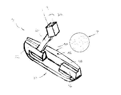
Figure 4 is a perspective view, from the rear, of the putter head and shaft.
DESCRIPTION OF PREFERRED EMBODIMENT
Figures 1- 4 show a p~ ed embodiment of a putter, indicated generally by
reference numeral 5, supported or held in a generally vertical or playing orientation. The
putter 5 has a putter head 10 which is attached to a putter shaft 30 by a connecting arm
20.
The putter head 10 is preferably made of a durable metal to avoid breakage during
play and transportation. It may be cast in a one piece construction that includes the
connecting arm 20. The head has a generally vertical surface 40 at the front for striking a
golf ball 7 (illustrated in fig.4), and weighted portions or blocks 12 and 16 in the rear
typically used to provide a desired balance to the head. The connecting arm 20 is attached
to the block 12 near the heel of the putter head at an angle "P" to the putter head. The
putter shaft 30 is in turn connected to the connecting arm 20 at an angle "S" to the putter
head as shown in fig.2. The shaft 30 is also tilted at an angle "H" to the vertical and is
slightly off-set from the connecting arm 20 (see fig.3) to f~çilit~te the visibility of the
striking surface 40 when the putter is held by a golfer. Good results have been achieved
with the following angles: P and S about 23 degrees, and H about 3 degrees.
The putter head's bottom surface 17 is substantially flat intermediate its curved rear
(i.e. heel) and front (i.e. toe) ends, 17a and 17b, respectively, as shown in fig.2. The
bottom surface 17 is also cambered slightly upwardly in a transverse direction, namely
between the front and rear ends 40 and 44, respectively, as shown in fig.3.
An important aspect of the putter head 10 is the shape of the striking surface 40.
The surface 40 is bowed outwardly in a horizontal plane (i.e. as viewed in fig.1) to form a
smoothly curved or "convex" striking surface. The surface 40 is substantially flat in a
-- 2 -

CA 0221~689 1997-09-16
vertical plane (i.e. as viewed in fig.3). Good results have been achieved using an
elliptically shaped striking surface. The use of the putter striking surface 40 which is
convex horizontally and fiat vertically appears to provide several advantages over existing
conventional putters, including enhanced putting results. First, the combination of a
striking surface with a convex horizontal curvature and a flat vertical face provides ease of
alignment with the ball, and hence improved accuracy of a putt in the direction struck, as
the apex of the convex striking surface of the putter head is directed to strike the apex of
the spherical ball, even if the club head twists slightly in the horizontal plane. The
curvature also reduces the zone of impact between the club and ball, which should reduce
vibration in the club and in turn provide a better and softer feel to hitting the ball. Further,
the striking surface 40 imparts a forward roll to the golf ball at impact, thereby reducing
the skidding effect normally experienced by the ball as it begins its motion on the grass
putting surface. The ball also appears to roll further with a given striking force in
comparison to conventional putters.
For ease of the above noted alignment, the putter head's top surface 18 has an
alignment sight 46 marked thereon located at the apex of the convex striking surface and
roughly equidistant between the heel 13 and toe 15. The sight mark 46 indicates the
preferred point of impact, or sweet spot, for hitting the ball. The mark is generally located
in alignment with central axis 32 of club shaft 30 (see fig.2) and between the weight
balancing blocks 12 and 16, respectively. It may now be better appreciated that as long as
a player using the putter head of the present invention strikes the ball in the proper
direction and in ~lignment with the mark 46 of the club head, the ball should travel toward
the intended target even if the head twists slightly.
The above description is intended in an illustrative rather than restrictive sense and
variations to the specific configurations described may be apparelll to skilled persons in
adapting the present invention to specific applications. Such variations are intended to
form part of the present invention insofar as they are within the spirit and scope of the
claims.

Representative Drawing
A single figure which represents the drawing illustrating the invention.
Administrative Status

2024-08-01:As part of the Next Generation Patents (NGP) transition, the Canadian Patents Database (CPD) now contains a more detailed Event History, which replicates the Event Log of our new back-office solution.

Please note that "Inactive:" events refers to events no longer in use in our new back-office solution.

For a clearer understanding of the status of the application/patent presented on this page, the site Disclaimer , as well as the definitions for Patent , Event History , Maintenance Fee  and Payment History  should be consulted.

Event History

Description Date
Revocation of Agent Requirements Determined Compliant 2022-04-01
Inactive: IPC deactivated 2015-03-14
Inactive: First IPC from PCS 2015-01-17
Inactive: IPC from PCS 2015-01-17
Inactive: IPC expired 2015-01-01
Time Limit for Reversal Expired 2000-09-18
Application Not Reinstated by Deadline 2000-09-18
Inactive: Cover page published 1999-10-15
Deemed Abandoned - Failure to Respond to Maintenance Fee Notice 1999-09-16
Application Published (Open to Public Inspection) 1999-03-16
Inactive: Correspondence - Formalities 1998-10-13
Inactive: IPC assigned 1997-12-10
Classification Modified 1997-12-10
Inactive: First IPC assigned 1997-12-10
Inactive: Filing certificate - No RFE (English) 1997-11-21
Filing Requirements Determined Compliant 1997-11-21
Application Received - Regular National 1997-11-20

Abandonment History

Abandonment Date Reason Reinstatement Date
1999-09-16

Fee History

Fee Type Anniversary Year Due Date Paid Date
Application fee - small 1997-09-16
Owners on Record

Note: Records showing the ownership history in alphabetical order.

Current Owners on Record
GEORGE KARPUK
Past Owners on Record
None
Past Owners that do not appear in the "Owners on Record" listing will appear in other documentation within the application.
Documents

To view selected files, please enter reCAPTCHA code :


To view images, click a link in the Document Description column. To download the documents, select one or more checkboxes in the first column and then click the "Download Selected in PDF format (Zip Archive)" or the "Download Selected as Single PDF" button.

List of published and non-published patent-specific documents on the CPD .

If you have any difficulty accessing content, you can call the Client Service Centre at 1-866-997-1936 or send them an e-mail at CIPO Client Service Centre.


Document
Description 
Date
(yyyy-mm-dd) 
Number of pages   Size of Image (KB) 
Description 1997-09-16 3 146
Drawings 1997-09-16 2 37
Cover Page 1999-10-07 1 37
Abstract 1998-10-13 1 19
Claims 1998-10-13 2 89
Representative drawing 1999-10-07 1 11
Filing Certificate (English) 1997-11-21 1 164
Reminder of maintenance fee due 1999-05-18 1 112
Courtesy - Abandonment Letter (Maintenance Fee) 1999-10-14 1 184
Correspondence 1997-11-25 1 19
Correspondence 1998-10-13 6 214