Note: Descriptions are shown in the official language in which they were submitted.
-
CA 02215760 1997-09-16
PCT~US96/03430
W 096/29169
CHUCK HAVING FORMED JAWS
Background of the Invention
The present invention relates generally to
chucks for use with drills or other tool drivers.
Tool drivers of various types are well known,
including hand-actuated drivers as well as electric
or pneumatic drivers. Although twist drills are a
common tool utilized with such drivers, the tools
may also comprise screwdrivers, nut drivers, burrs,
mounted grinding stones and other cutting or
abrading tools. Since the tools may have shanks of
varying diameter or the cross-section of the tool
shank may be polygonal, the device is usually
provided with a chuck which is adjustable over a
relatively wide range. The chuck may be attached
to the output shaft of the driver by a threaded or
tapered bore.
A variety of chucks have been developed in the
art. In one form of chuck, three jaws are
circumferentially spaced by approximately 120
degrees from each other. Such jaws are constrained
by angularly disposed passageways in a body
attached to the driver's output shaft. These
passageways are configured so that rotation of the
body in one direction relative to a constrained nut
engaging the jaws will cause the jaws to grip the
cylindrical shank of a tool. Rotation of the body
in the opposite direction with respect to the
constrained nut releases the gripping relationship
of the jaws.
Such a chuck may be keyless if the relative
rotation between the body and the nut is effected
by hand. One example of such a chuck is disclosed
in U.S. Patent No. 5,348,317, entitled "Chuck.
This patent, which is commonly assigned to the
present assignee, is incorporated fully herein by
reference.
CA 0221~760 1997-09-16
W O96/29169 PCTrUS96/03430
The respective jaws of these chucks include a
generally oblique surface defining thereon a "bite"
for engaging the tool shank. In the past, the bite
has been formed by milling or gr;n~;ng a "blank"
piece of metal having a length substantially equal
to the finished length of the jaw. While this
techn; que generally produced suitable jaws, it has
not been without disadvantages. For example,
because the bite is formed by removal of metal, the
blank begins with a volume of metal significantly
greater than that of the finished jaw member. In a
mass production situation, the cost attributed to
the removed metal can be appreciable. Furthermore,
the milling or grinding operation utilized to form
the bite must be one of relative precision to
ensure that the jaw members properly converge to
grip the shank of a tool. Accordingly, milling or
grinding may introduce problems into the
manufacture of chucks.
Sl ~ry of the Invention
The present invention recognizes and addresses
the foregoing considerations and others of prior
art constructions and methods. Accordingly, it is
generally an object of the present invention to
provide an improved chuck.
It is a further object of the present
invention to provide a chuck incorporating a jaw
having a bite portion which is not formed by
milling or grinding.
It is a further object of the present
invention to provide a jaw having a bite portion
manipulatively formed by selective redistribution
of metal.
It is a further object of the present
invention to provide a method of making a jaw
member for use with such a chuck.
CA 02215760 1997-09-16
PCTnUS96/03430
W O96/29169
Some of these objects are achieved by a chuck
for use with a manual or powered driver having a
rotatable drive shaft. The chuck comprises a
generally cylindrical body member having a forward
portion and a rearward portion. The rearward
portion has an axial mating bore defined therein to
mate with the drive shaft of the driver. The
forward portion has an axial receiving bore defined
therein and further defines therethrough a
plurality of angularly disposed passageways which
intersect the receiving bore.
The chuck includes a plurality of elongated
jaws slidably positioned in each of the angularly
disposed passageways. Each such jaw includes a
cylindrical shank portion defining threads on an
o~ter surface thereof. The shank portion
integrally extends into a bite portion having a
generally oblique surface defining thereon a jaw
face. Each of the jaws further has a structural
grain orientation characteristic of at least the
bite portion being manipulatively formed of a
singular piece of metal selectively redistributed.
A nut is rotatably mounted relative to the body
member so as to engage the threads defined on the
jaws such that rotation of the nut will operate the
jaws.
A rotatable nut-engaging element may be
connected to the nut such that rotation thereof
causes the nut to also be rotated. In exemplary
constructions, such a nut-engaging element may
comprise a generally cylindrical sleeve member
received over the forward portion of the body
member. Preferably, such a sleeve member may
define a gripping surface on an outside thereof to
facilitate manual rotation. A rear sleeve member
may also be provided and received over the rearward
portion of the body member. In an exemplary
CA 0221~760 1997-09-16
PCT~US96103430
W 096/29169
construction, the chuck further includes a bearing
thrust ring located on the body member and at least
one anti-friction bearing disposed between the nut
and the thrust ring.
Other objects of the invention are achieved by
a method of making a jaw member for use with a
chuck of the type described. Such a method may
comprise the step of first providing a blank of a
selected metal. The blank is generally configured
as a cylinder of a first predetermined length. As
an additional step, the blank is manipulatively
formed by selective redistribution of metal into an
intermediate configuration having a second
predetermined length greater than the first
predetermined length. The intermediate
configuration has a generally cylindrical shank
portion integrally ext~n~;ng into a tapered
portion. The tapered portion has a third
predetermined length and is characterized by a
greater diameter at an intermediate location on the
blank ext~n~;ng into a lesser diameter at a first
end thereof. The tapered portion is then
manipulatively formed by selective redistribution
.,, . . , .. ~ ., , _ , .
of metal into a bite portion having a generally
oblique surface defining thereon a jaw face. The
bite portion has substantially the second
predetermined length and further has a cross-
sectional area at axial locations therealong
substantially equivalent to the cross-sectional
area of the tapered portion at corresponding axial
locations. As a result, a jaw member is produced
having a shank portion and a bite portion, as
desired.
In an exemplary method of the invention, a
circumferential chamfer is manipulatively formed by
selective redistribution of metal at the first end
of the blank prior to formation of the intermediate
_
CA 0221~760 1997-09-16
W O 96/29169 PCTrUS96/03430
=_ =
configuration. The chamfer defines a first end
face of the blank having a predetermined diameter.
Preferably, the tapered portion of the intermediate
configuration is formed to taper to a minimum
diameter at the first end of the blank
substantially eguivalent to the predetermined
diameter. The tapered portion is preferably
characterized by a bullet-shaped nonlinear taper.
A circumferential chamfer may also be formed
at a second end of the blank opposite the first
end. Furthermore, an angled end face may be
manipulatively formed at a first end of the blank
by selective redistribution of metal. As an
additional step, the diameter of the shank portion
may be manipulatively reduced to a second
predetermined diameter by selective redistribution
of metal.
Preferably, no external heat is applied the
material of the blank before formation or the
material is heated but not to a temperature
~xc~;"g generally 1000 degrees Fahrenheit prior
to manipulative forming thereof.
Other objects, features and aspects of the
present invention are discussed in greater detail
below.
Brief Description of the Drawinqs
A full and enabling disclosure of the present
invention, including the best mode thereof, to one
of ordinary skill in the art, is set forth more
particularly in the remainder of the specification,
including reference to the accompanying drawings,
in which:
Figure 1 is a longitudinal view, partially in
section, of a chuck constructed in accordance with
an embodiment of the present invention;
Figure 2 is an exploded view of the chuck
illustrated in Figure 1;
-
CA 0221~760 1997-09-16
W O96/29169 PCTrUS96/03430
Figure 3 is an enlarged perspective view of a
jaw member constructed in accordance with the
present invention;
Figure 4 is a diagrammatic representation of a
five-station forming machine which may be utilized
to produce a jaw member such as that shown in
Figure 3;
Figure 5A is a perspective view of a blank
which may be utilized as a starting piece of metal
to produce a jaw member such as that shown in
Figure 3;
Figure 5B diagrammatically illustrates the
blank of Figure 5A as severed from a coil of metal
wire;
Figure 6A illustrates the blank as formed
after a first stage of the machine of Figure 4;
Figure 6B illustrates a die utilized in the
machine of Figure 4 to produce the configuration of
Figure 6A;
Figure 7A illustrates the blank as formed
after a second stage of the machine of Figure 4;
Figure 7B illustrates a die utilized in the
machine of Figure 4 to produce the configuration of
Figure 7A;
Figure 8A illustrates the blank as formed
after a third stage of the machine of Figure 4;
Figure 8B illustrates a die utilized in the
machine of Figure 4 to produce the configuration of
Figure 8A;
Figure 9A is another view of the blank as it
appears as formed after the third stage of the
machine of Figure 4;
Figure 9B illustrates the blank as formed
after a fourth stage of the machine of Figure 4;
Figure gC illustrates a die utilized in the
machine of Figure 4 to produce the configuration of
Figure 9B;
CA 0221~760 1997-09-16
W O96/29169 PCTnUS96/03430
Figure 10 illustrates a die for use in the
fifth stage of the machine of Figure 4;
Figure 11 is an enlarged elevational view of
an inteL ~ te configuration of the blank as
formed after the third stage of the machine of
Figure 4;
Figure llA is a cross-sectional view as taken
along lines llA-llA of Figure 11;
Figure 12 is an enlarged cross-sectional view
of a jaw member as formed after the fifth stage of
the machine of Figure 4;
Figure 12A is a cross-sectional view as taken
along lines 12A-12A of Figure 12;
Figures 13 and 14 are respective
PhOtOmi~L GYL aphs at ten (10) times magnification of
an axial cross-section of a portion of a jaw formed
according to the present invention and a
corresponding portion of a jaw produced according
to a prior art method; and
Figures 15 and 16 are respective
photomicrographs at fifty (50) times magnification
of a transverse cross-section of a jaw formed
according to the present invention and a jaw
produced according to a prior art method.
Repeat use of reference characters in the
present specification and drawings is intended to
represent same or analogous features or elements of
the invention.
Detailed Descri~tion of Preferred Embodiments
It is to be understood by one of ordinary
skill in the art that the present discussion is a
description of exemplary embodiments only, and is
not intended as limiting the broader aspects of the
present invention, which broader aspects are
embodied in the exemplary constructions.
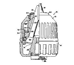
Figures 1 and 2 illustrate a keyless chuck lo
which will be used as a basis for explaining
CA 0221~760 1997-09-16
W O 96/29169 PCTrUS96/03430
certain aspects of the prese~t invention. In this
regard, chuck 10 is merely exemplary of a typical
chuck which may be improved according to the
invention. Thus, it is to be distinctly understood
that the present invention is not limited to the
operative configuration of the chuck illustrated.
Instead, aspects of the invention are applicable to
both keyed and keyless chucks of various operative
configurations.
Chuck 10 includes a front sleeve member 12, an
optional rear sleeve member 14, a body member 16
and a plurality of jaws 18. As shown, body member
16 is generally cylindrical in shape and comprises
a nose or forward portion 20 and a tail or rearward
portion 22. An axial receiving bore 24 is formed
in nose portion 20 of the body member 16.
Receiving bore 24 is somewhat larger than the
largest tool shank that chuck 10 is designed to
accommodate. A threaded bore 26 is formed in tail
portion 22 of body member 16 and is of a standard
size to make with the output shaft of a driver (not
shown) with which it will be utilized. Bores 24
and 26 may communicate at the central region 28 of
body member 16. While a threaded bore 26 is
illustrated, such bore could be replaced with a
tapered bore of a st~ rd size to mate with a
tapered drive shaft.
A plurality of passageways 30 are defined in
body member 16 to accommodate respective of jaws
18. Preferably, chuck 10 includes three (3) such
passageways 30 separated from each other in this
construction by an arc of approximately 120
degrees. The axes of passageways 30 and jaws 18
therein are angled with respect to the chuck axis,
3S intersecting the chuck axis at a common point ahead
of body - h~l- 16.
CA 0221~760 1997-09-16
W O96/29169 PCTrUS96/03430
Each of jaws 18 has a tool engaging face 32
which is generally parallel to the axis of body
he~ 16. Each of jaws 18 further defines threads
34 on an outer surface thereof generally opposite
engaging face 32. One skilled in the art will
appreciate that threads 34 may be of any suitable
type and pitch within the scope of the present
invention.
In this exemplary construction, body member 16
further includes a thrust ring member 36 which may
preferably be integral therewith. As shown, thrust
ring member 36 includes a thrust face 38 defining
an arcuate seating surface for engagement with the
inner race of a self-contained anti-friction
bearing assembly 40. Bearing assembly 40 includes
a plurality of bearing elements 42, here shown as
ball bearings. It will be appreciated that thrust
ring member 36 includes a plurality of jaw guide
ways 44 spaced apart around its circumference to
permit retraction of a respective jaw 18
therethrough.
Chuck 10 further includes a nut for engaging
the threads 34 of jaws 18. Rotation of the nut
with respect to body member 16 causes jaws 18 to be
advanced or retracted as desired. Although various
configurations of nuts may be utilized within the
scope of the present invention, the exemplary chuck
illustrated utilizes a split nut having
semicircular portions 46 and 48. Portions 46 and
48 have respective threads 50 and 52 defined on
their inner circumferential surface, as shown. A
retaining band 54 is provided to maintain portions
46 and 48 together as an annular nut when chuck 10
is assembled. It should be appreciated that a one-
piece nut, or any other suitable configuration,
could also be utilized for this purpose.
CA 0221~760 1997-09-16
W O 96/29169 PCT/U~ 3430
In this exemplary construction, front sleeve
member 12 is adapted to be loosely fitted over nose
section 20 of body member 16. As shown, front
sleeve member 12 includes drive ribs 56 which
engage slots 58 in portions 46 and 48. As a
result, front sleeve member 12 and the nut will be
operatively connected, i.e., when front sleeve
member 12 is rotated, the nut will rotate
therewith.
As shown, front sleeve member 12 includes an
annular ledge 60 adapted to rest against a ledge 62
at the base of nose section 20 of body member 16.
A nose piece 64 is placed on nose portion 20 behind
ledge 60 to maintain front sleeve member 12 in
position. In this case, nose piece 64 is
dimensioned to maintain a press fit on nose portion
20. It should be appreciated that nose piece 64
may also be secured in some cases by snap fit,
threading or the like.
As described above, chuck jaws have typically
been formed by milling or grinding a cylindrical
"blank." This technique requires that the blank
have at least the length and diameter as the jaw
into which it will be made. Metal removed in the
formation of the engaging face and other features
of the jaw is largely wasted.
Referring now to Figure 3, a jaw member 66
produced according to the present invention is
illustrated which may have threads defined thereon
to produce a jaw such as jaw 18. As can be seen,
jaw member 66 includes a shank portion 68
integrally extending into a bite portion 70. The
generally oblique surface 72 on bite portion 70
defines an engaging, or "jaw," face such as that
referenced as 32 in Figures 1 and 2. In the
illustrated embodiment, this engaging face is
formed to have a surface configuration in the
CA 0221~760 1997-09-16
W O96129169 PCTnUS~6/~ 0
11
direction transverse to its axial extent resembling
a "W." It should be appreciated, however, that
other suitable configurations, such as a "V," may
also be produced according to the present
invention.
A circumferential chamfer 74 may be defined at
the "trailing end" of member 66 adjacent shank
portion 68. An end face 76 is formed at the
opposite, "leading end" of member 66. End face 76
may be angled as shown along a plane so that
surface 72 extends axially farther than the arcuate
back 78 of bite portion 70. As a result of this
angled orientation, end face 76 will be
approximately perpendicular to the longitudinal
axis of chuck lO when installed therein.
As will now be described, member 66 has been
formed to this stage from a generally cylindrical
blank without removal of metal. In other words,
the various illustrated features including oblique
surface 72 and the jaw face defined thereon are
produced by "manipulative formation" of the blank.
In this process, the metal of the blank is
selectively redistributed so that these features
are produced.
Referring now to Figure 4, a forming machine
(generally indicated at 80) is diagrammatically
illustrated which may be utilized to manipulatively
produce a - h~r such as 66. As will be explained
more fully below, machine 80 includes a plurality
of stations at which various aspects occur in the
formation of member 66. In presently preferred
embodiments, machine 80 includes five (5) such
stations. Five (5) gripping or transfer
?c-h~n; c, such as that indicated at 82, are
provided to move the blank from station to station.
Machine 80 includes a first portion 84 and a
second portion 86 having planar faces situated in
CA 0221~760 1997-09-16
W O96129169 PCTrUS96/03430
12
opposition to one another as shown. In this case,
portion 86 is adapted to reciprocatively move with
respect to portion 84, as indicated by arrow 88.
Each forming station is represented in this view by
a hole 90 defined in face 92 of portion 84 and an
associated punch 94 extending from the opposing
face of portion 86. As portion 86 is moved toward
portion 84, the punch pushes the blank into the
associated hole. As a result of this movement, the
blank tends to conform to the shape of a die
located inside of portion 84 at the particular
station.
It will be appreciated that multiple stations
are provided in machine 80 so that member 66 may be
formed in multiple successive stages. This
technique is utilized because an attempt to form
member 66 from a generally cylindrical blank in one
stage would often be extremely difficult. By
forming member 66 in discrete stages, consistent
and effective manipulative formation thereof may be
achieved. Preferably, machine 80 has a blank at
each station during movement of portion 86 toward
portion 84. Thus, a number of blanks equal to the
number of stations will be in the process of being
formed in order to achieve manufacturing
efficiency.
The various stages through which a blank may
be formed into member 66 will now be described.
Figllre 5A illustrates a cylindrical blank 96 which
may be utilized to produce member 66 according to
the present invention. As shown, blank 96 has a
length L1 and a diameter sufficient to define a
volume of metal substantially equivalent to that of
member 66. As indicated in Figure 5B, blank 96 is
typically severed from a coil 100 of metal wire
utilizing a suitable cutting means. Generally,
blank 96 will be steel or an appropriate alloy
CA 0221~760 1997-09-16
W O96t29169 PCTrUS96/03430
13
thereof. For example, it is believed that a medium
carbon carbon steel, such as a steel having a 3 8-45
carbon range and some lead, may be suitable for
this purpose. Other suitable metals or appropriate
materials, however, may also be utilized within the
scope of the present invention.
Referring now to Figure 6A, a circumferential
chamfer 102 is formed at the leading end of blank
96 in the first stage of machine 80. Chamfer 102
defines a circular end face 104 having a diameter
D1. Chamfer 102 may be manipulatively formed by
pushing blank 96 into a complementary die 106 in
portion 84 via one of punches 94, such as that
shown in Figure 6B. As shown, blank 96 may retain
a length of approximately L1 at this stage.
After chamfer 102 is formed, punch 94 is
retracted. Blank 96 may then be removed from die
106 utilizing a removal pin inside of portion 84.
An axial passage 108 is defined in portion 84 so
that the removal pin can engage the leading end of
blank 96 and push it back out through the
respective of holes 90. Although not explicitly
described herein, it will be appreciated that other
stations of machine 80, except the final station in
many cases, will also typically use removal pins to
effect removal of blank 96 from the associated die.
The shape of blank 96 after the second stage
of machine 80 is illustrated in Figure 7A. As can
be seen, blank 96 is elongated in this intermediate
configuration to a length L2, which is preferably
greater than length L1. Here, blank 96 includes a
cylindrical shank portion 110 integrally extending
into a tapered portion 112. As shown, the diameter
of tapered portion 110 is progressively reduced in
the direction of end face 104, which preferably
remains substantially at the value of D1 after this
stage of manipulative formation.
CA 0221~760 1997-09-16
W O96/29169 PCTnUS96/03430
14
Preferably, tapered portion 112 has a "bullet
shape" in which the taper is nonlinear. As will be
explained more fully below, the cross-sectional
area of tapered portion 112 will preferably be
substantially equivalent to the cross-sectional
area of the desired final jaw member 66 at
corresponding axial locations. This configuration
facilitates the formation of the relatively complex
detail of the jaw face defined on oblique surface
72. An appropriate die for forming this
intermediate configuration of blank 96 is shown in
Figure 7B and referenced therein at 114.
Figure 8A illustrates the configuration of
blank 96 after the third stage of machine 80. As
shown, tapered portion 112 has now been formed into
a bite portion 116. Bite portion 116 includes a
generally oblique surface 118 defining thereon a
jaw face of the desired configuration. The back of
tapered portion 116 is configured as a generally
semi-circular surface 120 as shown. It will be
appreciated that semi-circular surface 120 will
have substantially the same radius as shank portion
110 and will be substantially a continuation
thereof.
End face 104 has been transformed into end
face 122 having the illustrated configuration. For
reasons which will be explained more fully below,
end face 122, while no longer circular in
configuration, will nevertheless have a surface
area substantially equivalent to end face 104. At
this stage, blank 96 will have a length of ~.
Length L3, which may be greater than length L1, will
preferably be substantially the final length of
member 66. A suitable die for forming this
iteration of blank 96 is illustrated in Figure 8B
and referenced therein as 124.
CA 0221~760 1997-09-16
W O96/29169 PCTnUS96/03430
Similar to Figure 8A, Figure 9A illustrates
the configuration of blank 96 after the third stage
of machine 80. In Figure 9A, however, a burr 122
such as may appear at the trailing end of blank 96
is shown in exaggerated form. Such a burr may be
caused by the successive pounding action of punches
94.
Figure 9B illustrates blank 96 as formed after
the fourth stage of machine 80. As can be seen,
the trailing end now has a circumferential chamfer
128 defined thereabout instead of burr 126.
Additionally, end face 122 has been angled as shown
to produce an angled end face 130.
Figure 9C illustrates a suitable die 132 for
use in producing this stage of blank 96 illustrated
in Figure 9B. It will be appreciated that blank 96
must be prevented from undesirable rotation in
clamping ?chAn;sm 82 when moved from the third
station to the fourth station to ensure that bite
portion 116 will be properly aligned in die 132.
Angled end face 132 may be formed by a
complementary surface on ejector pin 133, which
preferably remains in the position shown as blank
96 is inserted into die 132. Furthermore, to
produce chamfer 128, die 132 is configured so that
a portion 134 of the trailing end of blank 96 will
extend from face 92. Punch 94 is modified at this
station to define a recess 136 generally
complementary to chamfer 128. Engagement of blank
96 with recess 136 thus produces chamfer 128, as
desired.
At the fifth stage of machine 80, blank 96 is
subjected to a final sizing. Specifically, blank
96 is preferably passed through a bore 138 having a
reduced diameter portion 140. The inner diameter
of portion 140 is preferably substantially equal to
the desired outer diameter of member 66. Thus,
CA 0221~760 1997-09-16
W O96/29169 PCTrUS96/03430
16
after being passed through bore 138, blank 96 has
achieved the configuration of member 66 shown in
Figure 3.
Referring now to Figures 11 and 12, a
significant aspect of the present invention will
now be explained. Specifically, Figure 11
illustrates the intermediate configuration of blank
96 after the third stage of machine 80. As shown,
the length of tapered portion 112 from end face 104
to the location at which it extends into shank 110
may be expressed as length L4. Figure 12
illustrates member 66 after the fifth stage of
formation as A;cc~.c-ced above. As can be seen, the
length of bite portion 70 will generally also have
the length L4. Thus, a given axial location within
tapered portion 112 will correspond to a given
axial location within bite portion 70.
As illustrated in Figures llA and 12A, the
cross-section at respective of these axial
locations will have a different geometric
configuration. Nevertheless, the cross-sectional
area of ~ h~r 66 and blank 96 at corresponding
axial locations will be substantially equivalent.
This cross-sectional area may be designated as area
A.
The correspondence in area as described has
been found useful in manipulatively forming the
relatively complicated shape of bite portion 70
from a blank which is axially symmetrical. For
example, an attempt to produce bite portion 70
directly from a cylindrical blank may result in
"sticking" in the die. The present invention
eliminates such "sticking" and effectively produces
bite portion 70 by providing tapered portion 112
having cross-sectional areas equivalent to cross-
sectional areas in corresponding axial locations.
CA 0221~760 1997-09-16
W O96/29169 PCTnUS96/03430
17
This configuration allows the metal to be
effectively redistributed within the die.
An important aspect of the present invention
is the temperatures at which member 66 may be
formed. Specifically, member 66 may be formed at
temperatures significantly below the melting
temperature of the metal. Preferably, the
manipulative formation of blank 96 into member 66
is effected at applied temperatures which generally
do not ~Yc~e~ 1000 degrees Fahrenheit. Often, it
may be desirable to effect the manipulative
formation at room temperature although it should be
understood that friction during metal mo~ nt will
create an internal tr-_-~ature increase. In other
cases, it may be desirable to apply some external
heat to the material prior to formation. The
optimum temperature in such a situation will depend
on the particular material, but will generally be
less than 1000 degrees Fahrenheit as discussed
above. These relatively low temperatures are
desirable because shrinkage of blank 96 may be
experienced at higher temperatures, such as may be
used for hot forging.
Figures 13 and 14 are respective
photomi~L~yLaphs in axial cross-section of a
portion of a jaw produced according to the present
invention and according to prior art ma~ ; n; ng
t~chn; ques. The particular photomicrographs shown
have a magnification of ten (10) times. As can be
seen, the structural grain orientation of the
machined jaw is substantially axial throughout. On
the other hand, it can be seen that the structural
grain orientation of the jaw produced according to
the present invention is significantly different.
In this case, the grain is directionally oriented
to extend generally in parallel with the oblique
surface.
CA 0221~760 1997-09-16
W O96/29169 PCTrUS96/03430
18
Transverse cross-sections at fifty (50) times
magnification of a jaw member produced according to
the invention and prior art machining t~c-h~iques
are respectively shown in Figures 15 and 16.
Specifically, these photomi~ O~r aphs show a portion
of the "W" shape of the jaw face. In the prior art
jaw, it can be seen that the metallic grain is
oriented in a direction substantially orthogonal to
the photomicrograph. In other words, the grain
orientation extends "into" the photomicrograph
along the line of sight of the viewer. In the jaw
produced according to the present invention, on the
other hand, it can be seen that the structural
grain orientation follows to some extent the
configuration of the outer surface.
While preferred embodiments of the invention
and presently preferred methods of practicing the
same have been described, modifications and
variations may be practiced thereto by those of
ordinary skill in the art without departing from
the spirit and scope of the present invention,
which is more particularly set forth in the
appended claims. In addition, it should be
understood that aspects of the various embodiments
may be interchanged both in whole or in part.
Furthermore, those of ordinary skill in the art
will appreciate that the foregoing description is
by way of example only, and is not intended to be
limitative of the invention so further described in
such appended claims.