Language selection

Search

Patent 2215875 Summary

Third-party information liability

Some of the information on this Web page has been provided by external sources. The Government of Canada is not responsible for the accuracy, reliability or currency of the information supplied by external sources. Users wishing to rely upon this information should consult directly with the source of the information. Content provided by external sources is not subject to official languages, privacy and accessibility requirements.

Claims and Abstract availability

Any discrepancies in the text and image of the Claims and Abstract are due to differing posting times. Text of the Claims and Abstract are posted:

  • At the time the application is open to public inspection;
  • At the time of issue of the patent (grant).
(12) Patent: (11) CA 2215875
(54) English Title: APPARATUS FOR HIGH OXYGEN CONCENTRATION MEASUREMENT USING LIMITING CURRENT OXYGEN SENSOR
(54) French Title: APPAREIL DE MESURE DES FORTES CONCENTRATIONS D'OXYGENE AU MOYEN D'UN DETECTEUR D'OXYGENE A COURANT LIMITEUR
Status: Expired and beyond the Period of Reversal
Bibliographic Data
(51) International Patent Classification (IPC):
  • G01N 37/00 (2006.01)
  • G01N 27/00 (2006.01)
  • G01N 27/407 (2006.01)
  • G01N 33/00 (2006.01)
(72) Inventors :
  • CAO, TUAN QUOC (United States of America)
(73) Owners :
  • LITTON SYSTEMS, INC.
  • CARLETON LIFE SUPPORT SYSTEMS INC.
(71) Applicants :
  • LITTON SYSTEMS, INC. (United States of America)
(74) Agent: MARKS & CLERK
(74) Associate agent:
(45) Issued: 2002-06-04
(22) Filed Date: 1997-09-18
(41) Open to Public Inspection: 1998-08-05
Examination requested: 1999-01-07
Availability of licence: N/A
Dedicated to the Public: N/A
(25) Language of filing: English

Patent Cooperation Treaty (PCT): No

(30) Application Priority Data:
Application No. Country/Territory Date
08/796,084 (United States of America) 1997-02-05

Abstracts

English Abstract


A gas analysis apparatus using multiple orifices of
preselected sizes to attain a calculated gas mixing ratio for
diluting an oxygen sample to a concentration less than 95% prior to
application to a limiting current oxygen sensor. The apparatus
comprises a regulator for regulating the pressures of incoming
flows of air and oxygen sample to be measured, a valve for allowing
the concentration of the air sample to oxygen sample to be
measured, and a system for calculating the air sample/oxygen sample
mixing ratio based on the known air sample concentration and then,
based on the known air concentration and calculated mixing ratio,
calculating the unknown sample concentration from the output of the
oxygen sensor.


Claims

Note: Claims are shown in the official language in which they were submitted.

6
I Claim:
1. An gas analysis apparatus for measuring high concentrations of
oxygen, comprising:
a sample port for receiving a sample flow of one of either a
calibration gas having a known oxygen concentration (Cc) or a
sample gas having an unknown oxygen concentration (Cs) of up to
100%;
an ambient air port for receiving an air flow of ambient air
having predetermined oxygen concentration (Ca);
a limiting current oxygen sensor having inputs connected to
said sample port and said ambient air port for receiving a diluted
oxygen mixture of said sample flow and said air flow in a known
proportion and in the event said sample flow is calibration gas
generating a calibration reading (Cr) indicating oxygen content in
said mixture of calibration gas and air flow, and in the event said
sample flow is sample gas generating a mixture concentration
reading (Cm) indicating oxygen content in said mixture of sample
gas and air flow; and
a controller connected to said limiting current oxygen sensor
for receiving and storing said known oxygen concentration (Cc) of
said calibration gas, said predetermined oxygen concentration (Ca)
of said air flow, said calibration reading (Cr) and said mixture
concentration reading (Cm) and in response calculating said unknown
oxygen concentration (Cs) in said sample gas.
2. The apparatus of claim 1, further comprising a regulator
connected to said sample port and said ambient air port for
regulating each said sample flow and said air flow to a
predetermined pressure.

7
3. The apparatus of claim 2, further comprising an
additional regulator for further regulating the pressure of
said mixture to a second predetermined pressure when the
sensor is operated with variable ambient pressure.
4. The apparatus of claim 2, further comprising a valve
connected to a first input of said sensor and to said
regulator for selecting one of either (i) said sample flow
or (ii) said air flow to said sensor, a second input of said
sensor being connected to said ambient air port, whereby
said sensor measures oxygen concentration (Cm) of said
mixture when said valve selects said sample flow and said
sensor measures oxygen concentration (Ca) of said air flow
when said valve selects said air flow.
5. The apparatus of claim 1, wherein said controller further
comprises means for calculating said unknown oxygen
concentration (Cs) in said sample gas via a mathematical
operation utilizing linear approximation.
6. The apparatus of claim 5, wherein said means for
calculating implements said linear approximation as follows:
<IMG>
7. A gas analyser method for measuring high oxygen
concentrations of up to 100% in a sample gas, using a
limiting current oxygen sensor, comprising the steps of:
applying a mixture with known proportions of
calibration gas having a known oxygen concentration (Cc) and
ambient air having a known oxygen concentration (Ca) to said
limiting current oxygen sensor which, in response generates
a calibration reading (Cr)

8
indicating oxygen content in said mixture of calibration gas and
air;
storing said known oxygen concentrations (Cc and Ca) and said
calibration reading (Cr);
applying a diluted oxygen mixture of said sample gas and
ambient air in a known proportion to said limiting current oxygen
sensor which, in response generates a mixture concentration reading
(Cm) indicating oxygen content in said mixture of sample gas and
air;
storing said mixture concentration reading (Cm);
retrieving said known oxygen concentrations (Cc and Ca), said
calibration reading (Cr) and said mixture concentration reading
(Cm); and
calculating oxygen concentration (Cs) in said sample gas as
follows:
<IMG>
8. The method of claim 7, further comprising the steps of
separately applying said ambient air to said limiting current
sensor which, in response generates an adjusted air concentration
reading (Ca') indicating oxygen content in said ambient air and
calculating oxygen concentration (Cs) in said sample gas as
follows:
<IMG>

Description

Note: Descriptions are shown in the official language in which they were submitted.


CA 02215875 1997-09-18
ADnaratUS for High Oaveen Concentration Measurement Using Limiting Current
Oavgen Sensor
Field of the Invention
The present invention relates in general to limiting current oxygen sensors,
and
more particularly to an apparatus for high oxygen concentration measurement
using
limiting current oxygen sensors.
1o Background of the Invention
Solid state limiting current oxygen sensors are used in many applications,
ranging
from atmospheric measurements, combustion control, to oxygen concentrators for
high
performance aircraft. One such application is discussed in U.S. Patent
5,071,453
~ 5 assigned to Litton Systems, Inc. The basic structure comprises a zirconia
electrolyte
element comprising ZrOz - Yz03 in the shape of a disk which is heated to a
temperature in
the range of 400 - 700°C by means of an applied heating voltage of 1.7 -
3.0 VDC. A
pair of porous platinum electrodes are provided on opposite sides of the
zirconia disk to
which a known voltage is applied, resulting in generation of a limiting
current within the
20 disk which is related to the oxygen concentration of the sample applied to
the disk, as
discussed below. The entire structure is encapsulated with diffusion holes on
opposite
sides of the disk.
Limiting current sensors are characterized by a number of advantages over
other
25 prior art sensors, such as longer operating lifetime (e.g. more than 10,000
hours), high
accuracy (e.g. typically within t 0.5% O~, and compact size.
It is well known that such sensors suffer from severe limitations when
measuring
very high oxygen concentrations. More particularly, the output characteristic
for such
30 sensors is given by the equation:

CA 02215875 1997-09-18
2
Output = C In (1 -02%), where C is a constant.
Therefore, for OZ% = 100%, the Output = C In (I-1) _ ~. Accordingly, most
sensors of this type are rated only for operation below 95% oxygen
concentration. For a
more detailed discussion of the limitations of prior art oxygen sensors of
this type, see
Output Characteristics of Limiting Current Type Oxygen Sensor by Akiyohsi
Asada and
Tohsio Usui in Proceedings of the 6~ Sensor Symposium, 1986, pp. 257-260.
to It is desirable in many applications to measure oxygen concentrations in
excess of
95% by means of a limiting current oxygen sensor, in order to enjoy the
advantages such
sensors offer in terms of operating life, compact size, etc.
Summary of the Invention
According to the present invention, an apparatus is provided for diluting an
oxygen
sample (which can be up to 100% 02), to a concentration less than 95% prior to
application to a limiting current oxygen sensor. The apparatus comprises a
regulator for
regulating the pressures of incoming flows of air and oxygen sample to be
measured, a
2o valve for allowing the concentration of the air sample to be measured, and
a system for
calculating the air/sample mixing ratio based on the known air sample
concentration and
then, based on the known air concentration and calculated mixing ratio,
calculating the
unknown sample concentration from the output of the oxygen sensor.
In the preferred embodiment, a further regulator is provided to regulate the
mixed
pressure of air and oxygen sample applied to the oxygen sensor when operating
with
variable ambient pressure (e.g. at different altitudes in an aircraft).

CA 02215875 1997-09-18
3
Brief Introduction to the Drawings
A detailed description of the preferred embodiment is provided herein below,
with
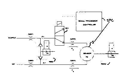
reference to the sole schematic illustration of an apparatus for high oxygen
concentration
measwement using a limiting current oxygen sensor.
Detailed Descriution of the Preferred Embodiment
1o Tunr~ing to Figure 1, the apparatus according to the preferred embodiment
is
shown comprising a sample/air pressure regulator with check valve (REG1) which
is
connected to the sample and air sources via orifices ORF 1 and O1ZF2. In
normal operation
the regulator ItEGI is set to operate at a predetermined pressure P1, for
regulating each
of the sample and air pressures to approximately P 1 (shown as P 1' and P 1 ",
respectively).
~5
A sliding solenoid valve (S V 1 ) alternately connects the regulated oxygen
sample
flow to an orifice (ORF3) or connects the regulated air flow to the orifice
ORF3 under
control of a signal processor controller (SPC). The signal processor
controller (SPC) is
also connected to oxygen sensor (S) for performing calculations based on
measured and
2o known oxygen concentrations, as discussed in greater detail below. The
regulated air flow
also passes to a further orifice (OltF4). The orifices OItF3 and OltF4 are
connected to
the housing {chamber) of oxygen sensor (S).
Therefore, during normal operation, the regulated sample and air flows are
applied
25 to the sensor chamber where the mixing action takes place, whereas during
air level check
both sides of the sensor receive only the regulated air flow.
A second regulator (REG2) is preferably provided to regulate the mixed sample

CA 02215875 1999-03-OS
4
and air pressure P2 at the sensor S when the sensor is operated
with variable ambient pressure (i.e. aircraft applications). At
ground level the regulator REG2 is not required since P2=ambient
pressure.
Since the sample pressure Pl', air pressure P1", and P2 are
constant, the flows across orifices ORF3 (flow indicated as Fs) and
ORF4 (flow indicated as Fa) are constant. Hence, the mixing ratio
of air and sample is also constant.
During calibration, a known gas (e.g. 99% 02 calibration gas
(Cc)) is applied to the sample port as sample along with air having
known oxygen concentration (e. g. 20.90 OZ air (Ca)). The oxygen
concentration of air (Ca) is determined during calibration by
energizing solenoid SV1, while the aircraft is on the ground. The
mixture concentration is then recorded along with the known
concentrations, for later use. Thus, if 99% 02 is used as
calibration gas (Cc), and the mixture reading is 680, then Cc=99o,
Cr=68o and Ca=20.9% oxygen in air are recorded as calibration
parameters.
During in-flight sensing, an air level check is performed
first (i.e. solenoid valve SV1 is energized), and the sensor S
tests the air source concentration of oxygen (e.g. 20.7a 02 air
concentration (Ca')). This concentration is used to calculate the
sample concentration.
Next, the solenoid valve SV1 is de-energized such that the
sensor S receives a mixture of air and sample (regulated flows Fa
and Fs). By knowing the air concentration and mixing ratio, the
unknown sample oxygen concentration can be calculated, from the
output current of the oxygen sensor based on the diluted sample

CA 02215875 1999-03-OS
applied to the sensor S, according to the sensor output
characteristic set forth above and using any one of a number of
calculation methods. One of the simplest methods of calculation
uses linear approximation. Using the example concentrations
discussed above, the linear approximation method is as follows:
1-During calibration with a diluted mixture of 990 oxygen
calibration gas (Cc) and 20.90 oxygen air (Ca); the calibration
reading (Cr) is 680. All of these concentrations are stored as
calibration parameters for later retrieval, as discussed above.
2-During normal operation (e. g. in-flight testing), assuming
that the mixture concentration reading (Cm) is 68.30, and assuming
that during the air check, the air concentration (Ca') was 20.70
oxygen, then
3-Using linear approximation, the sample concentration (Cs)
is: Cs = ((Cm - Ca') * (Cc - Ca)) / (Cr - Ca) + Ca';
or Cs = (68.3-20.7)*(99-20.9)/(68-20.9) + 20.7
- 99.6 0
As discussed above, the sensor S is capable of measuring
oxygen concentrations from 0 to 950. Depending on the sizes of the
orifices selected, the diluted or mixed sample will have an oxygen
concentration between 25 and 950, and preferably between 50 and
80%. The mixing ratio depends on the sample and air flows (Fs and
Fa). The flows depend on orifice sizes and the differential
pressures between P1' and P2 and between P1" and P2. It is well
within the skill of a person of ordinary skill in the art to
calculate the sizes of the orifices based on desired flows or
mixing ratio.
Alternatives and modifications of the invention are possible
without departing from the sphere and scope of the invention as set
forth in the claims appended hereto.

Representative Drawing
A single figure which represents the drawing illustrating the invention.
Administrative Status

2024-08-01:As part of the Next Generation Patents (NGP) transition, the Canadian Patents Database (CPD) now contains a more detailed Event History, which replicates the Event Log of our new back-office solution.

Please note that "Inactive:" events refers to events no longer in use in our new back-office solution.

For a clearer understanding of the status of the application/patent presented on this page, the site Disclaimer , as well as the definitions for Patent , Event History , Maintenance Fee  and Payment History  should be consulted.

Event History

Description Date
Time Limit for Reversal Expired 2007-09-18
Letter Sent 2006-09-18
Inactive: IPC from MCD 2006-03-12
Letter Sent 2003-12-02
Inactive: Multiple transfers 2003-10-30
Grant by Issuance 2002-06-04
Inactive: Cover page published 2002-06-03
Pre-grant 2002-03-21
Inactive: Final fee received 2002-03-21
Notice of Allowance is Issued 2002-02-12
Letter Sent 2002-02-12
Notice of Allowance is Issued 2002-02-12
Inactive: Approved for allowance (AFA) 2002-01-23
Amendment Received - Voluntary Amendment 2001-12-14
Amendment Received - Voluntary Amendment 1999-03-05
Letter Sent 1999-02-02
Request for Examination Requirements Determined Compliant 1999-01-07
All Requirements for Examination Determined Compliant 1999-01-07
Request for Examination Received 1999-01-07
Inactive: Correspondence - Transfer 1998-10-01
Inactive: Single transfer 1998-09-15
Application Published (Open to Public Inspection) 1998-08-05
Inactive: IPC assigned 1997-12-09
Classification Modified 1997-12-09
Inactive: IPC assigned 1997-12-09
Inactive: First IPC assigned 1997-12-09
Inactive: Courtesy letter - Evidence 1997-12-02
Inactive: Filing certificate - No RFE (English) 1997-11-24
Filing Requirements Determined Compliant 1997-11-24
Application Received - Regular National 1997-11-24

Abandonment History

There is no abandonment history.

Maintenance Fee

The last payment was received on 2001-06-14

Note : If the full payment has not been received on or before the date indicated, a further fee may be required which may be one of the following

  • the reinstatement fee;
  • the late payment fee; or
  • additional fee to reverse deemed expiry.

Please refer to the CIPO Patent Fees web page to see all current fee amounts.

Owners on Record

Note: Records showing the ownership history in alphabetical order.

Current Owners on Record
LITTON SYSTEMS, INC.
CARLETON LIFE SUPPORT SYSTEMS INC.
Past Owners on Record
TUAN QUOC CAO
Past Owners that do not appear in the "Owners on Record" listing will appear in other documentation within the application.
Documents

To view selected files, please enter reCAPTCHA code :


To view images, click a link in the Document Description column. To download the documents, select one or more checkboxes in the first column and then click the "Download Selected in PDF format (Zip Archive)" or the "Download Selected as Single PDF" button.

List of published and non-published patent-specific documents on the CPD .

If you have any difficulty accessing content, you can call the Client Service Centre at 1-866-997-1936 or send them an e-mail at CIPO Client Service Centre.


Document
Description 
Date
(yyyy-mm-dd) 
Number of pages   Size of Image (KB) 
Abstract 1997-09-18 1 15
Description 1997-09-18 5 184
Claims 1997-09-18 3 89
Drawings 1997-09-18 1 6
Cover Page 1998-08-05 1 46
Claims 2001-12-14 3 109
Claims 1999-03-05 3 111
Abstract 1999-03-05 1 21
Description 1999-03-05 5 199
Cover Page 2002-05-01 2 40
Representative drawing 1998-08-05 1 5
Filing Certificate (English) 1997-11-24 1 164
Request for evidence or missing transfer 1998-09-21 1 110
Courtesy - Certificate of registration (related document(s)) 1998-11-02 1 114
Acknowledgement of Request for Examination 1999-02-02 1 177
Reminder of maintenance fee due 1999-05-19 1 112
Commissioner's Notice - Application Found Allowable 2002-02-12 1 164
Maintenance Fee Notice 2006-11-14 1 173
Correspondence 2002-03-21 1 55
Correspondence 1997-11-21 1 41
Correspondence 1997-11-24 1 41
Correspondence 1997-11-28 1 35
Fees 1999-09-17 1 48
Fees 2001-06-14 1 53