Note: Descriptions are shown in the official language in which they were submitted.
W096/32864 CA 022164~4 1997-09-2~ PCT~S96/0501S
TITLE
CASSETTE ASSEMBLY AND UNIT DOSE
MEDICATION CART USING THE CASSETTE ASSEMBLY
BACKGROUND OF THE INVENTION
Field of the Invention
The invention relates generally to a mobile cart for
storing and transporting items, and more particularly
to a medication cart featuring a cassette assembly
ideally suited for storing and dispensing medication.
Description of the Prior Art
Mobile medication carts for storing medical and related
patient supplies have been used for many years.
Medication carts are typically used in hospitals or
other health care facilities, and are wheeled from room
to room transporting, for example, medication to be
dispensed to patients.
Two well-known medication carts are manufactured by
Drustar~ and Artromick Int'l.~. Both medication carts
use a cart frame supported on casters and are designed
to receive an array of drawers, multi-level cassettes,
shelves, etc. Each level of the cassette contains a
plurality of pull-out bins, with the bins on different
levels sometimes varying in size (i.e., width~. Both
medication carts also provide locking systems for
securing the medication and other items in the cart.
W096~2864 CA 022l64~4 l997-09-2~ PCT~S96/05015
In addition, Artromick Int'l.~ offers a patented drawer
slide module, which is the subject of U.S. Patent No.
5,211,461, for use with their medication cart.
The assignee of the subject application also
manufactures and sells medication carts. In one type
of mobile cart, known as the METRO~LEX~ cart, two
interlocking side/bottom panels are joined together to
form the lateral sides and bottom of the cart and a
back panel is secured to the side/bottom panels. A top
portion is added to complete a 3-sided enclosed cart.
The interior sides of the cart are corrugated to
support an array of differently sized drawers and bins,
and shelves or other accessories can be provided on the
outer sides of the cart. The ME~ROFLEX~ cart is the
subject of U.S. Patents No. 5,016,948 and No.
D 323,915.
However, further improvements in medication carts are
desired. For example, there is a need for a medication
cart with increased versatility and storage capacity as
well as offering superior construction and features.
SUMMARY OF THE INVENTION
It is a principal object of the invention to provide an
improved medication cart.
Accordingly, one object of the present invention is to
provide a medication cart with superior functional and
aesthetic design features.
In accordance with one aspect of the invention, a cart
comprises an enclosed structure including a plurality
of support posts, at least two side walls supported
between the support posts, with each side wall have a
corrugated interior surface, a bottom platform
W096/32864 CA 022164~4 1997-09-2~ PCT~S96105015
supporting the support posts and the side walls and a
top platform fitting over the support posts and the
side walls. In addition, locking means secures the
enclosed structure, and a cassette assembly is
removably supported in the enclosed structure. The
cassette assembly includes frame means having side
panels with a corrugated interior and ribbed outer
surfaces which engage the corrugated interior surface
of the side walls. At least one cassette tray is
supported in the frame means, and at least one bin is
received in the cassette tray. In addition, internal
locking means secures the bins in the enclosed
structure and external locking means secures the bins
within the frame means.
Another object of the invention is to provide a
controller for controlling operation of the locking
means.
Another object of the invention is to provide a
cassette assembly for use in the medication cart.
Yet another object of the invention is to provide a
cassette assembly that can be secured when disposed in
the medication cart and secured when removed from the
medication cart.
In accordance with another aspect of the invention, a
cassette assembly comprises frame means including side
panels with corrugated interior surfaces and ribbed
outer surfaces, at least one cassette tray slidably
supported in the frame means, and at least one bin
received in the cassette tray. Internal locking means
secures the bin in an enclosed structure, and external
locking means secures the bin within the frame means.
W096/32864 CA 022164~4 1997-09-2~ PCT~S96/05015
Still another object of the subject invention is to
provide a medication cart using a platform system
featuring flanged support posts and offset side panels.
In accordance with another aspect of the invention,
each support post in the medication cart includes an
elongated tubular post and a plurality of spaced
flanges ex~n~;n~ radially from the post and running in
a longitll~;n~l direction along the post. Each flange
has a first portion ext~n~;ng radially from the post
and a second portion ext~n~;ng from a terminal end of
the first portion.
These and other objects, aspects, features and
advantages of the present invention will become
apparent from the following detailed description of the
preferred embodiment taken in conjunction with the
accompanying drawings.
BRIEF DESCRIPTION OF THE DRAWINGS
Figure l is a perspective view of a medication cart in
accordance with the present invention;
Figure 2 is a perspective view of a support post in
accordance with the present invention;
Figure 3 is a top plan view of the support post shown
in Figure 2 in accordance with the present invention;
Figure 4 is a fragmented partial view of Figure 3,
isolating a slot in the support post in accordance with
the present invention;
Figure 5 is a perspective view of a frame assembly in
accordance with the present invention;
CA 022l64~4 l997-09-2~
W096/32864 PCT~S96/05015
Figure 6 is a perspective view of a modified interior
side panel for use in the frame assembly in accordance
with the present invention;
Figure 7A is a fragmented top plan view of a support
post in use in a back corner of an enclosed structure
in accordance with the present invention;
Figure 7B is a three-axis coordinate system and a
schematic view of a side panel in accordance with the
present invention;
Figure 8 is a fragmented top plan view of a support
post in use in a front corner of the enclosed structure
in accordance with the present invention;
Figure 9 is a perspective view of a multi-level
cassette assembly in accordance with the present
invention;
Figure 10 is a perspective view of a top or bottom
component of the cassette assembly in accordance with
the present invention;
Figure 11 is a perspective view of a right side panel
of the cassette assembly in accordance with the present
invention;
Figure 12 is a perspective view of a left side panel of
the cassette assembly in accordance with the present
invention;
Figure 13 is a perspective view of a cassette tray in
accordance with the present invention;
Figure 14 is a partial perspective view of'an underside
of the cassette tray shown in Figure 13;
W096/32864 CA 022l64~4 19s7-09-2~ PCT~S96/05015
-- 6
Figure 15 is a perspective view of a cassette bin in
accordance with the present invention;
Figure 16 is a perspective view of a label cover for
the cassette bin in accordance with the present
invention;
Figure 17(A) is a partial perspective view of the right
side panel and part of an external locking ~ech~n;s~ in
accordance with the present invention;
Figure 17(B) is a partial front elevational view of a
locking bar shown in Figure 17(A) in accordance with
the present invention;
Figure 17(C) is a cross-section of the locking bar
shown in Figure 17(B) in accordance with the present
invention;
Figure 18 is a perspective view of a drawer frame in
accordance with the present invention;
Figures l9(A) and l9(B) are perspective views of front
panel parts of the drawer frame in accordance with the
present invention;
Figure 20 is a partial cross-sectional view of the
drawer frame along lines 20-20 in Figure 18 in
accordance with the present invention;
Figure 21 is a perspective view of a drawer clip in
accordance with the present invention;
Figure 22 is a top view of the drawer clip shown in
Figure Z1 in accordance with the present invention;
W096/32864 CA 022164~4 1997-o9-2~ PCT~S96105015
Figure 23 is a perspective view of a single-depth
drawer assembly in accordance with the present
invention;
Figure 24 is a perspective view of a double-depth
drawer assembly in accordance with the present
invention;
Figure 25 is a perspective view of a drawer insert for
use in the drawer assembly in accordance with the
present invention;
Figure 26 is a perspective view of a lateral divider
for use in the drawer insert in accordance with the
present invention;
Figure 27 is a perspective view of the medication cart
with the side pods open in a swing-out position in
accordance with the present invention;
Figure 28 is a fragmented top view of a support post in
use in a front corner of the enclosed structure in
accordance with the present invention;
Figure 29 is a perspective view of an empty side pod in
accordance with the present invention;
Figure 30 is a perspective view of the side pod loaded
with bins in accordance with the present invention;
Figure 31 is a perspective view of a molded side panel
of the side pod in accordance with the present
lnvention;
Figure 32 is a perspective view of a shelf for use in
the side pod in accordance with the present invention;
W096/32864 CA 022l64~4 l997-09-2~ PCT~S96/05015
Figure 33 is a perspective view of a bin for use in the
side pods in accordance with the present invention;
.
Figure 34 is a perspective view of the side pod with a
door in accordance with the present invention;
Figure 35 is a perspective view of the side pod with a
door in accordance with the present invention;
Figures 36 and 37 are front and rear views,
respectively, of a locking bar in accordance with the
present invention;
Figure 38 is a perspective view of right side locking
fingers in accordance with present invention;
Figure 39 is a perspective view of left side locking
fingers in accordance with the present invention;
Figure 40 is a rear elevational view of the corrugated
interior panel in accordance with the present
invention;
Figure 41 is a partial front elevational view of the
corrugated interior panel in accordance with the
present invention;
Figure 42 is a front elevational view of a cam gear in
accordance with the present invention;
Figure 43 is a perspective view of a front corner of
the enclosed structure showing the locking bar in
operable engagement with a mechanical locking mech~n;~
in accordance with the present invention;
Figure 44 is a block diagram of the security system in
accordance with the present invention;
CA 022l64~4 l997-09-2
W096/32864 PCT~S96/0501
Figure 45 is a flowchart of the operation of the
security system in accordance with the present
invention;
Figure 46 is a flowchart of a routine for input and
validation of the ID/PIN in accordance with the present
invention;
Figure 47 is a flowchart of the unlock and auto-relock
routine in accordance with the present invention;
Figure 48 is a flowchart of the change PIN routine in
accordance with the present invention;
Figure 49 is a flowchart of the change date/time/unlock
time routine in accordance with the present invention;
Figure 50 is a flowchart of the input date routine in
accordance with the present invention;
Figure 51 is a flowchart of the audit of access record
routine in accordance with the present invention;
Figure 52 is a flowchart of the supervisor add/delete
PIN routine in accordance with present invention; and
Figure 53 is a schematic illustration of the keypad and
display in accordance with the present invention.
DESCRIPTION OF THE PREFERRED EMBODIMENTS
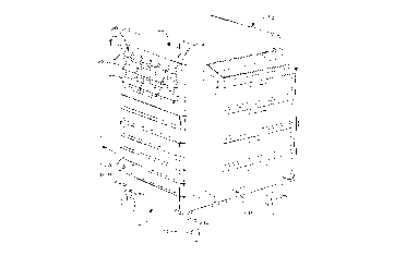
Figure 1 illustrates a medication cart lO in accordance
with the present invention. Generally, the cart
~ includes a frame assembly 12 supported on casters 14.
A plurality of drawers 16 of various sizes (i.e.,
depths) are slidably supported in the frame assembly,
and hinged side pods 18 are supported on the sides of
W096/32864 CA 022l64~4 lss7-09-2~ PCT~S96/05015
-- 10 --
the cart to swing out toward the front as discussed in
detail below.
The medication cart features a cassette ~s~hly 20
that includes a plurality of pull-out cassette bins
provided on different levels. In accordance with the
subject invention, the medication cart includes a
security system for preventing unauthorized access to
the drawers and the cassette bins, and the cassette
assembly includes its own security system for securing
the bins even when the cassette assembly is not in the
cart.
Details of the frame assembly 12 are shown in Figures 2
through 8. The frame assembly is based on a platform
system using a plurality of flanged support posts and
side panels.
A support post 30 in accordance with the subject
invention is illustrated in Figures 2, 3 and 4. The
support post 30 is generally comprised of an interior
post 32 and a plurality of radially ext~n~;ng, e~ually
spaced flanges 34. The post is designed to be
vertically disposed in normal use and can be supported
at its lower end by a base platform, a foot, a caster,
etc. In a single-wide platform, which is preferred for
the medication cart, four support posts are used
together to provide corner supports for the frame
assembly.
The interior post 32 is preferably tubular in shape,
with a circular cross-section and interior 36 and
exterior 38 concentric wall surfaces as best seen in
Figures 2 and 3. The flanges 34 preferably extend
along the entire longitll~;n~l length of the interior
post. In addition, the flanges and interior post are
preferably formed by conventional extrusion techniques
W096/3~64 CA 022164~4 1997-09-2~ PCT~S96/05015
to form an integral structure made of, for example,
aluminum. However, other comparable means, e.g.,
pultrusion, roll-formed steel, could be used to form
the support post in accordance with the subject
invention.
The flanges 34, or dovetails, are preferably spaced
equi-distant from each other around the periphery of
the interior post 32 to create a symmetrical support
post. Thus, four flanges would be spaced at 90~
intervals around the post. Although using four flanges
is preferred because of the versatility such an
arrangement provides, the number of flanges is
arbitrary and can vary without departing from the scope
of the invention. With reference to Figure 3, each
flange has a first portion 40 which extends radially
from the interior post 32. At the terminal end of each
first portion is a transversely-disposed second portion
42. The second portions are formed with arcuate outer
surfaces 44, that together outline a circumference that
is concentric with the interior 36 and exterior 38 wall
surfaces of the interior post 32. Referring to Figure
2, the outer surfaces 44 of each flange are formed with
a series of equally spaced circumferential grooves 46.
The vertically-spaced grooves are desirably provided
along the entire longitudinal length of the flanges.
In one embodiment, the outside diameter of the support
post, as defined by the arcuate outer surfaces 44, is
l.625" and the inside diameter is .875".
A slot 48 is formed between each pair of adjacent
flanges 34. Because of the arcuate shapes of the
exterior wall surface 38 and the flanges, the slots can
be described as substantially concave T-shaped, with
respect to a longitudinal axis of the support post.
With reference to Figure 4, each slot is shaped to have
concave-shaped opposite end surfaces 50 and 52. The
W096~2864 CA 022164~4 1997-o9-2~ PCT~S96/05015
- 12 -
exterior wall 38 forms a convex interior surface of the
slot. The contour of the end surfaces and outer wall
form a slot that is simple in design but provides
~; flexibility and support. In addition, the
curved single-wall design of the flanges makes
extrusion easier, is readily cleanable and allows the
support posts to be aesthetically integrated into the
finished structure as will be discussed in detail
below.
The frame assembly 12 in Figure 5 is built on a single-
wide platform constructed of four support posts 30. In
this embodiment, the support posts support two exterior
side panels 54 and a back panel 56 (unseen in Figure
6). In addition, interior side panels 58 are disposed
side-by-side adjacent to the exterior side panels 54.
Top and bottom platforms 60 and 62, respectively,
complete the frame assembly. The top platform houses a
me~n;cal locking me~-h~n;~m 64 and an electronic
controller 66, both used for operating a security
system that will be described in detail below. The
completed structure forms a 3-sided enclosed frame
assembly, with the front side, or fourth side, open to
receive an array of drawers, shelves, cassettes, etc.,
as discussed in detail below.
Each interior side panel includes a corrugated interior
surface 68 with an array of corrugations 70 adapted to
receive and support drawers, shelves, cassette
assemblies or other accessories. The horizontal
corrugations are uniformly spaced in the vertical
direction. Small, semicircular openings 72 can be seen
in the lateral front face of the interior side panel
~ tely below the end of each corrugation. The
openings extend to the underside of each corrugation
but cannot be seen in this view. The openings allow
locking fingers, which will be positioned in each
W096/32864 CA 022l64~4 lss7-09-2~ PCT~S96/05015
corrugations as discussed below, to move in and out of
the corrugations as part of the security system that
will be discussed below. Openings can also be provided
along the right-hand side of the interior panel 58 for
the same purpose.
v
The top and bottom platforms 60 and 62 are preferably
formed of a metal frame fitted with a plastic cover.
As shown in Figure 5, the top platform has a
substantially rectangular shape for fitting over the
four support posts 30. The bottom platform 6Z is
preferably designed, at least in a single-wide
platform, to have a "C"-shape formed to have two
extending legs 74 defining an open front portion 76.
By cutting out the front portion of the bottom
platform, the overall appearance of the cart is
enhanced, especially when drawers or other accessories
are not disposed in the lower part of the cart.
Both top and bottom platforms can be secured to the
support posts by using threaded plugs (unshown) that
are force-fitted, for example, in opposite ends of each
support post and threaded fastening means fed through
the top and bottom platforms and into the plugs. In
assembling the enclosed frame assembly, each support
post is positioned on the base platform fitted with its
cover, and a threaded bolt or other fastener is
inserted through a hole in the platform from the
underside and into engagement with the threaded plug.
The side panels are then top loaded into the support
posts. Threaded fasteners are inserted through the
~ metal frame of the top platform and into the plugs at
the top ends of the support posts. Finally, the top
cover is fitted over the top platform. Of course,
other comparable means for securing the platforms to
the support posts could be used.
W096/32864 CA 022164~4 1997-o9-2~ PCT~S96/05015
In the single-wide platform design as discussed above,
the enclosed frame assembly preferably has one support
post 30 positioned at each of four corners. In this
design, the ~u~OL ~ posts are spaced, for example,
19.8" from center to center. Of course, the spacing of
the posts is arbitrary and can be varied to construct
different size and shaped structures. A "double-wide"
design platform includes, in addition to four corner
posts, a rear center post and, in an enclosed frame
assembly, a front center post.
A slightly modified interior side panel 58' is shown in
Figure 6. The modi~ied side panel 58' differs from the
side panel 58 only in that each corrugation 70 is
formed in two halves to define a dividing slot 74 that
runs the vertical length of the side panel. The
modified panel can be used in a two-sided enclosed
structure, i.e., a dual access cart, whereby the front
and back are open to receive, for example, a cassette
assembly or drawers. In a dual access cart, a thin,
flat panel (unshown) can be secured in the dividing
slot 74 for dividing the interior of the frame assembly
in half.
A recessed opening, or pocket, 76 in the lower part of
the interior surface 68 and pockets 78 in the back of
the interior side panel 58' (and 58) are provided to
house various components of the security system.
Offset lateral ends, or edges, 80 of the interior panel
are received in slots 48 in the support posts as
discussed below to secure the side panel.
All of the side panels can be made of a polymer
material, e.g., polyethylene, and are preferably blow
molded or formed by other comparable means to form a
hollow, two-faced structure. The interior side panels
W096/32864 CA 022164~4 1997-09-2~ PCT~S96/05015
- 15 -
58 are also compression molded in part as discussed
below.
..
Figures 7A and 8 are top views of the support posts 30
engaging side panels in accordance with the present
invention. As discussed above, the side panels are
top-loaded into the slots 48 of the support posts and
rest on the bottom platform, or base, 62.
Figure 7A is a partial top view of the support post 30
in use as a right rear support (with reference from the
front side of the cart). Clockwise in this ~igure, the
support post 30 secures an interior side panel 58, a
back side panel 56, a blank extrusion 80 and an
exterior side panel 54. The blank extrusion 80 is
essentially a linear trim piece of molded plastic,
preferably ext~n~;ng the length of the support post,
that is inserted into an empty slot 48 for aesthetic
purposes, i.e., to provide a finished look to the
enclosed structure.
As Figure 7A shows, each side panel is shaped to have a
neck portion 82 and a head portion 84 forming each
lateral end for engagement in the support post. The
head portion is shaped to compliment the shape of the
slots 48. In addition, each neck portion is offset
from its respective panel. Using the exterior side
panel 54 in Figure 7A as an example, and using the
coordinate system in Figure 7B as a reference, the side
panel has a longitudinal axis A running in the height-
wise direction (in the Z-axis direction), a lateral
axis B in the widthwise direction (Y-axis) and an
orthogonal axis C representing its depth (X-axis).
- Axis C is orthogonal to both axes A and B. Likewise,
the head portion 84 has its own longitudinal axis E,
lateral axis F and orthogonal offset axis G. In
accordance with the subject invention, the offset axis
W096l32864 CA 022l64~4 l997-09-2~ PCT~S96/05015
- 16 -
G of the head portion is transverse to the lateral axis
B of the panel. In this manner, a contour fit is
achieved between the panels and the support posts. As
will also be appreciated, lateral axes M of the flanges
34 extend in directions either parallel with or
perpendicular to the lateral axes (axis B) of the
panels they secure. This arrangement allows the
support posts to be visually integrated into the
structure and provide a clean, aesthetically-pleasing
appearance.
Figure 8 illustrates a support post 30 in use as a
right front support in an enclosed structure. In
Figure 8, the slots 48 in the support post 30 receive
an exterior side panel 54, an interior side panel 58
and a blank extrusion 80 in the same manner as
described above in Figure 7A. In the remaining slot is
secured a drawer-abutting extrusion 86 for abutting,
e.g., a drawer 16 that is slidably received in the
enclosed frame assembly. As discussed in detail below,
the drawer is provided with a surface, e.g., one or
more ribs, that is slidably supported on the corrugated
surface 68 of the interior side panel 58. As shown in
Figure 8, the drawer-abutting extrusion 86, which is
preferably a resilient plastic, includes an abutting
face 88 for contacting the fully closed drawer and a
locking face 90 for contacting a part of the drawer and
preventing it from being accidentally pulled out.
A multi-level cassette assembly 20 in accordance with
the present invention is shown generally in Figure 9.
A frame 102 of the cassette assembly is formed by a top
component 104, which includes a handle 106, a plurality
of side panels 108, a bottom component 110 and a back
panel (unshown). The bottom component can be
essentially the same piece as the top component but
W096/32864 CA 022l64~4 lss7-09-2~ PCT~S96105015
does not include a handle. An isolated view of the top
(or bottom) ~. ~ ent 104 is provided by Figure 10.
The multi-level cassette assembly supports a cassette
tray 112 on each level, and each cassette tray contains
a plurality of pull-out cassette bins 22. A lock 114,
which is part of an external locking m~-h~n; ~m ~ is
secured in a front face of the top assembly. While the
cassette assembly in this figure provides three levels,
the number of levels (which corresponds to the number
of cassette trays) can of course vary without departing
from the scope of the invention. The components
comprising the cassette assembly are preferably made of
a polymer plastic, e.g., ABS, and can be formed by
conventional molding t~-hn;ques.
The side panels 108 are shown in detail in Figures 11
and 12, with Figure 11 illustrating a right side panel
for use on the right-hand side of the cassette assembly
and Figure 12 showing a left side panel for use on the
left-hand side of the cassette assembly. A single
right and left side panel are used for each level of
the cassette assembly. Each side panel is preferably
an integrally formed piece of molded plastic.
With reference first to Figure 11, the side panel
includes a lateral face 116 formed with two elongated
ribs 118. The ribs are shaped to complement the
corrugated surface of the interior side panels 58 as
discussed above. At the front of each rib 118 is an
open slot 119 for receiving a component of the security
system which will be discussed below. The top and
bottom edges of the side panel are provided with a
- plurality of male/female connectors 120/122 for snap-
fitting the side panel to other side panels or top or
bottom components when assembling the cassette
W096/32864 CA 022l64~4 lss7-09-2~ PCT~S96/0501
- 18 -
assembly. The male connectors 120 are best seen in
Figure 12.
At the rear end of the side panel is formed a U-shaped
panel interface 124 for receiving the flat back panel
of the cassette assembly. A ~ront edge 126 of the side
panel is formed to have both an elongated slot 12~ and
a through-hole 130 running through it. The slot
receives part of the external locking ~?ch~n i ~m that
will be described below. A hollow rod (unshown) made
of, for example, aluminum is inserted through the hole
and stabilizes the assembled cassette frame.
Figure 12 best illustrates the corrugated interior
surface of the side panel. Corrugations 132 form a
slot 134 therebetween for receiving the cassette tray
112. Elongated recesses 136 formed in the corrugations
interface with the cassette tray in a manner described
below.
To assemble the frame, the side panels are snap-fitted
together using the male and ~emale connectors to
provide as many levels as desired. The formed left and
right sides can then be snap-fitted to the bottom
component and a back panel can be fit into the panel
interfaces in the side panels and into a portion of the
bottom component. Hollow rods can then be loaded into
the elongated holes 130 in both right and left side
panels, and the external locking m~ch~n;sm is
positioned in the elongated slot in the right side
panels. The top component can now be placed on the
side walls. Screws or other fasteners are then
inserted through holes 131 in the top and bottom
components and into threaded ends of the hollow rods to
complete the assembly.
CA 022l64~4 l997-09-2~
W096/32864 PCT~S96/05015
-- 19 --
The cassette tray 112 that is received in each level of
the cassette assembly is shown in Figures 13 and 14.
With reference to Figure 13, the cassette tray is
formed to have a flat bottom surface 138 surrounded on
three sides by a vertical edge 140. At the front of
the tray is a front face 142 which provides a small lip
144 at the front edge of the bottom surface 138. The
edges on the left and right sides of the tray extend
into horizontal ledges 146 for resting on the
corrugation 132 in the side panels 108 of the frame. A
channel 148 with a notched portion 150 is formed at the
front part of the ledges. The notched portion is part
of an internal locking assembly and will be engaged by
a locking finger to secure the tray in the cassette
assembly frame.
Figure 14 shows an underside of the cassette tray and
illustrates a flexible latch 152 that forms part of the
external locking assembly. The latch is cantilevered
from the front face and includes, at its free end, an
abutting face 154 and a sloping, or angled, face 156.
The sloping face allows the latch to flex upwardly when
receiving a horizontal force. A small block 158
located beneath the notched portion 150 will interface
25 with the recess 136 in the corrugation 132 and indicate
a normal stop position of the cassette tray as it is
withdrawn from the frame.
The cassette tray 112 supports a plurality of bins 22
as shown in Figure 9. The size (i.e., width) of the
bins can be varied to best fit the end-user's needs.
~ For example, Figure 9 shows a cassette assembly with 6
bins supported on the top level, 4 bins supported on
- the middle level and 3 bins supported on the lower
level. An individual bin 22 is illustrated in Figure
15.
W096~2864 CA 022l64~4 l997-09-2~ PCT~S96/05015
- 20 -
A bin label cover 160 for ret~in;ng a label on the bin
22 is shown in Figure 16. The label cover, which is
preferably formed of clear or otherwise transparent
plastic, includes front notches 162 and arcuate rear
grooves 164. The notches and grooves interact with
small protrusions (unseen) inside the bin, and allow
the label cover to pivot about the protrusions in the
front notches. Identifying labels can thus be easily
placed (and changed) between the label cover and a
front face 166 of the bin.
Figures 17(A)-17(C) show additional components of the
external locking assembly. This locking assembly is
designed to lock the cassette trays 112 when the
cassette assembly is removed, i.e., external, from the
medical cart, hence the name 'lexternal locking
?ch~; cm, ~ An internal locking mPch~n;~ in the frame
assembly secures the cassette trays when the cassette
assembly is inserted in the medication cart.
With reference to Figure 17(A), a bolt lock 168, which
is mounted in the top assembly 104 as shown in Figure
9, actuates a saw-tooth locking bar 170 to operate the
external locking assembly. The bolt lock, which is
conventional ~er se, includes a locking barrel 172 and
an extended T-bolt 174 that moves in and out of the
barrel when a key is inserted into the lock barrel and
turned 180~. Bolt locks manufactured by the HURD LOCK
Co. (H75N and H75C series), in Greeneville, TN, have
been successfully used in the external locking
assembly. Comparable assemblies besides the bolt lock
could be used to actuate the locking bar without
departing ~rom the scope of the invention. A pin 176
extends from the T-bolt and engages an angled slot 178
in the flag-shaped top portion 180 of the locking bar
170. A vertical slot 182 in the top portion interfaces
W096l32864 CA 022l64~4 lss7-09-2~ PCT~S96/05015
- 21 -
with the top assembly 104 to vertically guide the
locking bar.
A partial front view of the locking bar 17 is shown in
Figure 17(B). The locking bar is preferably formed
from'metal, e.g., steel, and is shaped to include an
elongated bar 171 and at least one locking tooth 184.
A relief 173 is shown at the lower end for metal
forming purposes (i.e., to help bend the metal).
Another relief for the same purpose is provided toward
the upper end of the elongated bar 171. The elongated
bar is formed, e.g., bent, to have an L-shaped cross-
section as evident in Figure 17(C). A first leg 173 of
the bar fits in elongated slot 128 in the side panels.
Only one locking bar is normally provided in each
cassette assembly and usually disposed in the right
side panels. A plurality of the teeth 184 are evenly
spaced along the length of the locking bar. One tooth
is preferably provided for each side panel and moves,
with actuation of the locking bar, in and out of a
locking position. In the locking position the tooth
184 is substantially even with the lower corrugation
132 (i.e., the bottom of the slot 134).
Figure 17(A) shows the locking bar in the up, or
locked, position, whereby the tooth 184 will engage the
latch 152 on the underside of the cassette tray. In
this position, engagement between the tooth and the
abutting face 154 of the latch will prevent the
cassette tray from being withdrawn.
If the cassette tray is already withdrawn when the
external locking assembly is actuated, the shape and
- flexibility of the latch permit the tray to be inserted
into the cassette assembly frame and subsequently
locked. When inserting the tray, the flexible latch
will bias upwardly when the sloping face 156 slides
W096/32864 CA 022l64~4 l997-09-2~ PCT~S96/05015
over the tooth, thus allowing the drawer to be inserted
and locked.
To unlock the cassette assembly, the bolt nut is
actuated to move the T-bolt and thus the pin 176 in the
direction of arrow x. This sliding movement forces the
locking bar downward through a c~;ng action between
the pin and the angled slot 178. In the down position,
the cassette tray is free to slide in and out of the
cassette assembly frame.
The external locking assembly has been disclosed in
terms of locking the cassette trays. As will be
appreciated, however, locking the cassette trays
effectively locks the bins and prevents access to the
contents therein. By virtue of the vertical lip 144 on
the cassette tray 112 and the close fit between the
structure immediately above the bins, i.e., either the
front face of another cassette tray or the top
assembly, the individual bins cannot be withdrawn
unless the cassette tray is slid out a su~ficient
amount, e.g., one inch, such that the bin can be li~ted
over the vertical lip and then slidably withdrawn.
Thus, by preventing the cassette tray from being
withdrawn, the bins can be securely locked.
Details of a drawer assembly for use in the medication
cart are shown in Figures 18 through 26. In accordance
with the subject invention, the drawer assembly
features an open architecture type of construction
which uses one standard type o~ drawer ~rame for
drawers o~ di~erent sizes, i.e., depths.
A standard drawer frame 200 is shown in Figure 18 to
include two side panels 202 fastened between a handle
drawer front 204 and a rear panel 206. The handle
drawer front 204 is shown in isolation in Figures 19(A)
W096/32864 CA 022l64~4 l997-09-2~ PCT~S96/05015
- 23 -
and l9(B). The ~ront handle section, which is
preferably molded plastic, is actually formed from two
pieces for ease of production: a recessed front face
208 and a handle 210. The recessed front face 208
shown in Figure l9(A) includes opposite arms 212 that
are secured, such as by threaded fasteners, to the side
panels 202 of the frame. Each arm 212 includes a
notched channel 214 for receiving a locking finger as
discussed in detail below. The notched channel 214
permits the drawer assembly to be securely locked in
the enclosed structure. The plastic handle 210, as
shown in Figure l9B, is snap-fitted to the front face
to complete the front handle section.
The side panels and rear panel are formed of, for
example, aluminum, and secured to each other by common
fasteners 216, such as screws. Each side panel
includes a formed channel 218 on its exterior surface
for slidably receiving a drawer glide 220. The drawer
glide, by virtue of its elongated, rectangularly-shaped
outer side, slides between the corrugations 70 in the
interior side panels 58 to support the drawer assembly
in the enclosed frame assembly.
As best seen in Figure 20, which depicts a cross-
section of the drawer glide 220 and the side panel, the
drawer glide has a T-shaped cross-section which
complements the shape of the channel 218. The drawer
glide is also provided with a cut-out notch 222 in its
back surface. The notch extends from a rear end of the
drawer glide to an intermediate, e.g., halfway, point
of the drawer glide. The notch allows the drawer glide
220 to slide over the head of the screw 216 up to the
- intermediate point where the notch terminates. By
allowing the drawer glide to slide relative to the side
panel 202, the drawer frame can be pulled further out
of the enclosed frame assembly to allow better access
W096l3~64 CA 022l64~4 l997-09-2~ PCT~S96/05015
- 24 -
to the contents in the drawer. The intermediate end of
the notch limits the relative movement between the
drawer glide and the side panel to prevent the drawer
glide from sliding out o~ the drawer frame.
A drawer clip 224 as shown in Figures 21 and 22 is
provided in each drawer glide 220 to prevent the drawer
assembly from accidentally being pulled completely out
of the medication cart. With reference to these
figures, the integral drawer clip 224 is molded from a
non-rigid plastic, such as nylon, to have a short leg
226 and a long leg 228. The long leg is formed with a
stop 230, that includes a ramped portion 232 and an
abutting face 234, and a finger tab 236. The long and
short legs meet to form an angle of approximately 100~,
as best seen in Figure 22, with the short leg fitting
into an opening, such as slot 238, in the drawer glide.
As shown in Figures 23 and 24, when the drawer clip is
positioned in the drawer glide 220, it is almost flush
therewith, except for the stop 230, which extends
outwardly a short distance, e.g., 1/8." When pulling
out the drawer assembly, the drawer glides slide along
the corrugated side panel until the abutting face 234
25 of the stop 230 abuts the locking face 90 of the
drawer-abutting extrusion 86 ~see Figure 8), at which
point the drawer cannot be slid out further until the
finger tabs 236 on each drawer clip are depressed into
a recess 240 in the drawer glide. Depressing the
finger tabs withdraws the stop and allows the drawer
clips to pass by the drawer-abutting extrusions.
Reinserting the drawer assembly is unimpeded because
contact between the ramped portion 232 of the drawer
clip 224 and the drawer-abutting extrusion biases the
drawer clip inwardly, making it possible to slide in
the drawer.
W096/32864 CA 022l64~4 lss7-09-2~ PCT~S96/05015
- 25 -
Figures 23 and 24 further illustrate the open
architecture type of drawer assembly. A single-depth
drawer 16(A) in Figure 23 shows a drawer insert 242,
which is essentially a 4-sided bin, supported on the
5 drawer frame 200. An isolated view of the bin 242 is
provided in Figure 25. The drawer insert includes a
lip 244 for resting on the side and rear panels of the
drawer frame, and can also include slots 246 for
receiving optional bin dividers 248. Additional
lateral dividers 250 can be positioned on the bin
dividers 248 to further divide the drawer insert. One
type of lateral divider is shown in Figure 26 and is
discussed below.
In accordance with the invention, the drawer insert 242
can be of any desired depth. However, when the drawer
insert is deeper than the handle drawer front 204 of
single-depth drawer 16(A), the standard drawer frame
200 is supplemented with one or more blank drawer
20 fronts 252. For example, Figure 24 shows a double-
depth drawer 16(B), so-called because two-front
sections--a handle drawer front 204 and a blank drawer
front 252, are secured together to form the front of
the drawer assembly.
For simplicity, drawer inserts 243 can be provided in
standard depths of, for example, 3", 6" and 9". Each
drawer front is sized to cover a 3" depth of the drawer
insert. Therefore, a handle drawer front would be used
30 with a 3" deep drawer insert, a handle drawer front and
a blank drawer front would be used with a 6" deep
r drawer insert, and so on. For drawer assemblies of 6"
and 9", a gusset 254 can be secured between the blank
drawer front(s) 252 and the side panels 64 on each side
35 of the drawer frame for additional rigidity.
W096f32864 CA 022l64~4 l997-09-2~ PCT~S96/05015
- 26 -
The lateral divider 250 shown in Figure 26 includes a
U-shaped cap 256 for fitting over a longitll~i n~ 1
divider 248 and scored sections 258 that can be snapped
off where appropriate to adjust the length of the
lateral divider.
The side pods 18 are preferably secured to the
medication cart by a hinge, such as a conventional
piano hinge, so they can swing open toward the front of
the cart. In Eigure 1, the side pods 18 are closed and
positioned to rest against the sides of the cart.
Figure 27 shows the hinged side pods 18 in the open
position, with bins 260 in the side pods flanking the
front side of the cart.
Figure 28 is a top view of the front right corner of
the medication cart and illustrates a hinge 262 secured
to the exterior side panel 84. The hinge mounts a back
panel of the side pod 18 to the exterior side panel 54
and allows the side pod to pivot about hinge pin 264 to
swing toward the front of the cart. Also shown in
Figure 28 is the interior side panel 58, drawer-
abutting extrusion 86, blank extrusion 80 and, of
course, the flanged support post 30.
As best seen in Figures 29 and 30, the individual side
pod is formed from two side panels 266 secured to a
back panel 268. A utility shelf 270 is positioned
between the two side panels. The side and back panels
are preferably blow molded and secured to each other by
conventional fasteners. The back panel is formed to
have a plurality of vertical slots 272 in its interior
surface. The slots can be provided with tabs 273 for
securing, for example, an unshown horizontal rail for
supporting medical instruments, tools, and other
accessories. As an additional feature, a vertical
W096132864 CA 022164~4 1997-09-2~ PCT~S96tO5015
- 27 -
support (unshown), or bracket, can be key-fitted in a
tab for supporting a partial-length horizontal shelf.
With reference to Figure 29 and the isolated view of a
side panel 266 in Figure 31, the interior surface of
the side panels 266 are formed to have a vertical array
of molded, or configured, sections 274. Each molded
section includes a horizontal slot 276 for supporting,
as an example, a horizontal shelf 278, which is molded,
or more particularly extruded, as shown in Figure 32.
The plastic shelf 278 is reversible and can be provided
with a lip 280 along its front edge. In this manner,
one side of the shelf provides a smooth, flat surface
and the other side of the shelf uses the lip as an edge
to help retain items supported on the shelf. Each
molded section also includes a rear arcuate slot 282
and a front notch 284 for receiving a bin 260 of the
type shown in Figure 33.
The bin 260 includes a handle 286 and two sets of pins
288 and 290 extending from the lower lateral sides of
the bin. For reference purposes, the first set of pins
288 is disposed directly below the handle and the
second set of pins 290 is disposed opposite to the
first set. To insert the bin in a frontward position,
i.e., with the handle on the outside, the bin is tilted
to place the first set of pins 288 in the notches 284
and the second set of pins 290 is guided into the
arcuate slots 282. The bin can then be rotated into
the cabinet to rest in an upright position. In this
position, the bin can be tilted outwardly by holding
the handle and rotating the bin about the first set of
pins 288. The bin can also be mounted in a rearward
position, i.e., with the handle on the inside of the
cabinet, to provide a deep shelf. To achieve this
position, the second set of pins 290 are first inserted
W096/328~ CA 022l64~4 l997-09-2~ PCT~S96/05015
- 28 -
into the notches 284 and the bin is tilted inward, with
the first set of pins sliding in the arcuate slots 282.
The side panels 266 also include a groove 292 rl7nning
along the front inner edge for receiving a door 294,
such as a tambour door, as shown in Figure 34. The
tambour door, ~er se, is conventional and, as known,
can be formed from a plurality of parallel sections
joined together such as to exhibit flexibility in one
direction and rigidity in a perpendicular direction.
Figure 34 shows the door secured to a locking shelf 296
positioned in an uppermost horizontal slot 276 in the
side pod. The locking shelf can be formed by modifying
the shelf 278 shown in Figure 32 to provide a slightly
enlarged front edge for housing a simple manual locking
m~h~n;~r 298 such as a key lock and a rotatable
locking finger (unshown) for securing the tambour door.
The locking shelf can be easily located in any
horizontal slot in the side panels for altering the
portion of the cabinet which can be secured to best fit
the user's needs. For example, Figure 35 shows the
locking shelf 296 disposed at approximately the mid-
portion of the side pod.
Another feature of the swing-out side pods is the
provision of a swing-out work surface 300 that provides
additional work space when the side pods are in the
open position. As shown in Figure 27, the work surface
is substantially a flat shelf, preferably a quarter-
circle in shape to ~;~ize the work surface area, andis secured to a top portion of the back panel of each
side pod. When the side pods are closed, the work
surface slides under the top platform 60 of the cart
and out of sight. Since both side pods are preferably
equipped with swing-out work surfaces, these work
surfaces are secured at slightly different vertical
CA 022l64~4 l997-09-2~
W096l32864 PCT~S96/05015
- 29 -
heights on their respective side pods so they will
avoid each other when sliding under the top platform.
While the side pod is ideally suited to be swingably
mounted to a medication cart as discussed above, it can
also be mounted to the sides of the cart so as not to
swing and, as additional non-limiting examples, mounted
to a wall, a work station, or a stationary cabinet.
The side pod could also be provided on its own wheeled
cart or caddy.
An internal locking assembly, or security system, with
both manual and electric controls can be provided in
the frame assembly to lock and secure the drawers and
cassette assembly. In one application, the medication
cart is used to store and transport items such as drugs
or other medicine, surgical tools, etc. in the drawers
and cassette assembly that should be secured to prevent
unauthorized use or consumption. Generally speaking,
the security system features an elongated locking bar
disposed in one o~ the interior side panels 58. The
locking bar is moved up and down along its vertical
axis to actuate locking ~ingers, housed in the
corrugations, to engage and lock the individual drawers
and the cassette assembly.
The security system is housed, for the most part, in
the interior side panel 58. With reference back to
Figure 6, a recessed pocket 76 on the interior side
panel 58 receives and secures therein an electric
motor, an electronic control card and a backup battery
(all unshown in this figure). The locking bar is
positioned in an extended locking finger clearance
pocket 78 formed in the rear side of the interior side
panel. Two of these clearance pockets can be provided
in the side panel, as shown in Figure 6, to provide the
option of mounting the locking bar in either side of
W096/32864 CA 022l64~4 l997-09-2~ PCT~S96/05015
- 30 -
the panel. However, only one locking bar is normally
mounted in the side panel.
A front and rear view of the locking bar 302 is shown
in Figures 36 and 37, respectively. The elongated
locking bar is preferably formed from metal, such as
.075" steel (14 gauge), and includes two holes 304 at
the top for interfacing with the m~ch~n;cal locking
?c-h~n;~ as described below. As best seen in Figure
37, a plurality of locking fingers 306 are secured
along the length of the locking bar. The locking
fingers are evenly spaced and will be housed in
corrugations 70 of the interior side panel 58 when the
locking bar is properly positioned.
Figure 38 illustrates a set of three "right-hand"
locking fingers 306 to be secured on the locking bar
302. The right hand locking fingers will be housed in
an interior side panel secured on the right side of the
enclosed structure. Figure 39 illustrates "left-hand"
locking fingers for use on the left side of the
enclosed structure. The fingers are preferably grouped
in sets of three, or sometimes four, for ease of
attachment to the locking bar. Each set of fingers is
preferably an integrally formed structure made of a
resilient plastic, such as nylon, to impart flexibility
to the individual fingers. Each finger includes a
lateral arm 308 and an angular tip 310. An extension
312 joins each arm to a common base 314. In a three-
finger set, as shown in Figure 38, the base 314
includes one scored section 316 for separating the
fingers as necessary. The base 314 includes a
plurality of holes 318 for receiving rivets or other
fasteners for attaching the locking fingers to the
locking bar. In addition, a rib 320, which is best
seen in the left-hand fingers shown in Figure 39, can
also be provided as a stabilizer. The angular tip 310
W096/32864 CA 022164~4 1997-o9-2~ PCT~S96/05015
- 31 -
includes an angled face 322 and an abutting face 324,
with a front face 326 joining the angled and abutting
faces.
Figure 40 is a rear view of the interior side panel S8,
showing the locking bar 302 positioned in the locking
finger clearance pocket 78 in the left side (from the
rear view) of the panel. As will be appreciated by
those skilled in the art, the side panel in Figure 40
can be formed by a combination of blow molding and
compression molding. The middle portion of the panel
is hollow as a result of the blow molding. However, a
subsequent processing step, such as ma~-h;n;ng or
compression molding, forms the locking finger clearance
pockets 78 on the right and left sides of the panel.
Part of the corrugations 70 can be seen in the locking
finger clearance pockets. As seen from this view, each
corrugation has an opening 72 in its underside, with
the opening ext~n~;ng in a semicircular shape to a
lateral face of the side panel immediately below the
corrugation. When the locking bar is positioned in the
clearance pocket, as shown in the left side of the side
panel in Figure 40, a locking finger 306 is positioned
in each corrugation. A partial front view of the
corrugated side panel 58 with two locking fingers 306
positioned in corrugations is shown in Figure 41. In
this figure, the locking fingers are extending through
the openings 72 in the underside of the corrugations,
and thus in their locked position.
With reference to Figure 40, the lower end of the
locking bar is operably engaged to an electric motor
328. The electric motor and an unshown battery operate
to actuate the locking bar 302 up and down along its
3S longitudinal axis. A rotatable shaft 330 extends from
the motor and has mounted thereon a cam 332 for
engaging the locking bar. A shown in Figure 42, the
W O 96/32864 CA 022l64~4 l997-09-2~ PC~rrUS96/05015
cam can have a propeller-like shape so that each
quarter turn of the shaft will raise or lower the
locking bar.
The electronic motor and the battery are controlled by
an electronic locking m~hAn; ~m that will be described
below in detail. When the motor is operated to actuate
the locking bar, the locking fingers likewise move up
or down to extend the tip 310 either in or out of its
respective corrugation. When the locking bar is in the
"down", or home, position, the locking finger tips 310
extend through the openings 72 and engages the notched
channel Z14 (see Figures 23 and 24) in the drawer
frame. In this locked position, the notched channel is
lS engaged by the abutting face 324 of the locking finger
and the drawer cannot be withdrawn. With respect to
the cassette assembly, the locking fingers in the
locked position project through the slots 119 in the
ribs 118 and engage the notched portion 150 of the
cassette tray.
When the locking bar is raised and thus in the up, or
unlocked, position, the locking finger tips 310 are
retracted within the corrugations and the drawers slide
freely in and out of the medication cart. Likewise,
the cassette trays are free to slide in and out of the
cassette assembly, and the cassette assembly itself can
also be withdrawn from the medication cart.
In accordance with the subject invention, even if a
drawer or a cassette tray is not fully inserted in the
enclosed frame assembly, e.g., a cassette tray is open,
when the locking bar is in the locked position, the
drawer or cassette tray can subsequently be closed and
will automatically lock. This feature is made possible
by the shape and flexibility of the locking fingers.
For example, when a withdrawn cassette tray is closed
W096/32864 CA 022l64~4 l997-09-2~ PCT~S96/05015
- 33 -
after the locking bar is locked, the channel 148 of the
drawer frame will abut the angled face 322 of the
locking fingers. The angled face permits the sliding
cassette tray to impart an upward force to the locking
finger, which in response will flex upwardly and allow
the cassette tray to continue sliding until the notched
portion 150 receives the finger tip 310. At this
point, the locking finger will return to its unbiased
state and lock the cassette tray.
While the locking bar 302 can be actuated by the
electric motor, it can also be actuated by operation of
a mechanical locking mech~n;s~. With reference to
Figure 43, the independent m~c-h~n;cal locking m~c-h~n;~m
333 includes a key-operated lock 334 and a pin 336
extending from the lock. An S-shaped link 338 is
secured to the interior side panel 58 by a retainer
clip 340. One end of the link extends through the hole
304 in the top end of the locking bar and the other
(second) end of the link is in contact with the pin
336. To raise the locking bar and lift the locking
fingers, thus unlocking the medication cart, a key is
inserted into the lock and turned to rotate the pin in
the clockwise direction. This clockwise movement
lowers the second end of the link 338 and therefor
raises the first end of the link to lift the locking
bar.
The electronic locking me~-h~n;~ is operated by an
electronic control system. In Figure 44, reference
numeral 1900 schematically represents the cart or other
enclosed structure, reference numeral 1700 represents
the electronic control system for controlling the
security system, reference numeral 1702 represents the
central processing unit (CPU), reference numeral 1704
represents a display, reference numeral 1706 represents
memory, reference numeral 1708 represents a clock and
W096/32864 CA 022l64~4 lss7-09-25 PCT~S96/0501S
- 34 -
calendar, reference numeral 1710 represents a power
supply, reference numeral 1712 represents a lock motor,
reference numeral 1714 represents an input and ouL~L
port (I/O port), reference numeral 1716 represents a
motion sensor, reference numeral 1718 represents a
battery warning light, and reference numeral 1720
represents a keypad. Each of the items identified
above are shown in block outline because they are well
known, E~E se, and a specific type of construction is
not critical to carrying out the invention or to a
disclosure of the best mode for carrying out the
invention.
In more detail, CPU 1702 preferably comprises a
microprocessor or the like, and is connected to display
1704, memory 1706, clock/calendar 1708, power supply
1710, lock motor 1712, I/O port 1714, motion sensor
1716, and keypad 1720. Display 1704 comprises a 16
character alphanumeric LCD display or the like and
includes a battery warning light, and is also shown in
Figure 53. Memory 1706 comprises non-volatile memory,
RAM, ROM, and the like. Power supply 1710 preferably
comprises a rechargeable nicad battery, featuring
unattended fast charging with automatic kick-down to
standby charging. Power supply 1710 also allows for
connection for wall powered use independent from
battery presence or charge level. The power supply
comprises circuity (not shown) to survive accidental
connection to other than a supplied wall transformer~
e.g., A.C. or D.C. of less than 30 volts. Furthermore,
the power supply 1710 also comprises a backup lithium
cell, preferably with a life expectancy of over five
years. The lock motor 1712 is protected from peak turn
on current by an active current limiting circuit (not
shown). I/O port 1714 comprises a st~n~rd port for
interconnection with a personal computer. Motion
sensor 1716 is optional and could comprise, for
CA 022l64~4 l997-09-2~
W096/32864 PCT~S96105015
example, a circuit using a limit switch that detects if
the lock bar has reached an expected position. Keypad
1720 (Figures 44 and 53) preferably comprises a
membrane touchpad with ENTER key 2910, CLEAR key 2912,
0 through 9 keys generally shown as 2950, and other
operation keys including a LOCK key 2922, PIN key 2914,
TIME key 2916, AUDIT key 2918, and ADD/DEL key 2920.
The battery warning light on the display 1704 is
illuminated by CPU 1702 if the battery power is below a
predetermined level.
A control program for the electronic control is stored
in memory 1706, and preferably in non-volatile memory.
The control program serves to perform locking,
unlocking, and various supervisory functions in
response to user input from keypad 1720. Figure 45
depicts a flowchart representing the main operation of
the control program. When left unattended, the system
enters into a sleeping, or stand-by, mode to conserve
power. User input, as in step 2002 in Figure 45,
awakens the system, which then performs functions in
accordance with the keys pressed.
If the user presses the 0-9 keys on keypad 1720, the
control program branches in step 2004 (Figure 45) to an
unlock and auto-relock routine 1100. Turning to Figure
47, in step 1102, the program inputs the ID and PIN
from keypad 1720.
Step 1102 is shown in more detail in Figure 46. Figure
46 depicts a routine for inputting and validating the
ID/PIN. Step 1002 sets a count variable to zero. The
program inputs the ID and PIN in step 1004. The ID
comprises a two digit number (00-99), and the PIN
comprises a four digit number (0000-9999). Together,
the ID and PIN comprise a user code. Of course, these
choices are exemplary and could be changed to allow any
W096/32864 CA 022l64~4 l997-09-2~ pcrlus96lo5ol5
-- 36 --
specified number of digits for each of the ID and PIN.
In any case, if the ID and PIN are found to be valid in
step 1006, then the routine returns. If the ID and PIN
are not found to be valid in step 1006, then control
br~n~-he~ to step 1008, where the count variable is
increased. If the count variable is found to be
greater than three in step 1010, then access is derlied
in step 1012. In step 1012, the security system will
remain locked for a supervisory--selectable number of
minutes (LOCKOUT TIME). However, if the count variable
is found to be less than or equal to three in step
1010, then the routine returns to step 1004 to allow
the user to enter the ID and PIN again.
Assuming that the user has entered a valid ID/PIN, the
Figure 46 routine for inputting and validating the
ID/PIN returns to the Figure 47 unlock and auto--relock
routine, as discussed above. The unlock and auto--
relock routine in Figure 47 continues processing with
step 1104. In step 1104, the CPU 1702 controls the
lock motor 1712 to unlock the cart. In step 1106, the
control program begins a timing operation. To inform
the user of the remaining time, the CPU 1702 controls
the display 1704 to display a status message. The
status message preferably includes an alternating
display of "XX MIN TO RELOCK" and "BATTERY E(****)F",
wherein XX represents the number of minutes until auto-
relock, and the latter display represents the amount of
charge r~;n;ng on the battery (hereinafter referred
to as the "battery charge message"). Step lloO checks
to see if the time is up, i.e., if the time has reached
an AUTO--RELOCK TIME. This time can be changed by a
user's supervisor for security purposes. If time is
not up in step 1110, then in step 1112, it is checked
whether the LOCK key has been pressed. If not, then
the program returns to display status step 1108. Once
time is up in step 1110, or if the lock key has been
W096/32864 CA 022l64~4 19s7-09-2~ PCT~S96105015
- 37 -
pressed in step 1112, then CPU 1702 controls lock motor
1712 in step 1114 to lock the cart. When the cart has
been locked, CPU 1702 controls display 1704 to display
a lock status display, preferably for about 15 seconds,
5 after which the display is shut off. The lock status
display preferably comprises an alternating "LOCKED"
message and the above-described battery charge message.
If the optional motion sensor 1716 is included in the
10 electronic control system, then the control program
being executed by CPU 1702 uses the motion sensor 1716
to determine if the locking operation was successful.
Specifically, in step 1114, after the CPU 1702 has
controlled lock motor 1712 to lock the cart, the CPU
15 receives signals from motion sensor 1716 representative
of a state of the limit switch. If the limit switch
(not shown) r~;n~ open for 12 seconds, for example,
the motor is turned off, and then step 1116 displays an
"UNLOCK ERROR" rather than the above-discussed lock
20 status display. Such unlock errors are stored in
memory 1706, preferably in non-volatile memory. The
motion sensor operates in the same manner to determine
if an unlocking operation was successful, i.e., i~ the
limit switch does not change states after 12 seconds,
25 the motor is turned off and an error signal is
displayed and stored in memory 1706.
While the cart is unlocked, and the unlock and auto-
relock routine in Figure 47 is operating, the other
30 functions of the main operation of the control program
(Figure 45) are available on an interrupt basis.
f Specifically, while the unlock and auto-relock routine
in Figure 47 is passing through the steps 1108, 1110,
and 1112, if the user presses any of the function keys
35 (e.g., ADD/DEL, TIME, etc.), that respective routine
(e.g., ADD/DEL, TIME, etc.) will be performed.
Thereafter, the flow returns to the unlock and auto-
W096/32864 CA 022l64~4 19s7-09-2~ PCT~S96/05015
- 38 -
relock routine and the timer (step 1106) is reset to
begin counting down again from the m~; m~
predetermined auto-relock time.
To unlock the cart, the user must enter a PIN, as
described above; however, the user may wish to change
his or her PIN for security purposes. Also, the
supervisor may wish to change a user's PIN. Figure 48
shows a "change PIN" routine 1300. This routine would
be selected, as shown in Figure 45, if the PIN key is
pressed (step 2008). Returning to Figure 48, in step
1302, the user (or supervisor) enters the user code
(ID/PIN). Step 1302 follows the procedure of Figure
46, as described above. Assuming that a valid ID/PIN
has been entered, in step 1304 the prompt "NEW PIN" is
displayed on display 1704, and the user may input a new
PIN via keypad 1720. The new PIN is displayed in step
1306, by an alternating display between "NEW PIN: ~#~"
and "ENTER OR CLEAR." User input is accepted in step
1308 (during which time the alternating display
continues). In step 1310, if the ENTER key has been
pressed, then the new PIN is stored in step 1314. If
in step 1310, the ENTER key has not been pressed, then
it is determined in step 1312 if the CLEAR key has been
pressed. If so, the routine returns to step 1304 to
input a new PIN (although not shown, if the user
presses the CLEAR key twice, the routine ends). If the
user has not pressed CLEAR (step 1312), then the user
has pressed neither CLEAR nor ENTER, therefore the
routine returns to step 1308.
Returning to Figure 45, if the PIN key has not been
selected in step 2008, then step 2010 determines if the
TIME key has been selected. If so, then the change
date/time/unlock time routine of step 1400 is selected.
Figure 49 depicts this routine in detail. First, a
valid ID/PIN is input in step 1402. The current date
W096/32864 CA 022l64~4 lss7-09-2~ PCT~S96105015
- 39 -
is displayed in step 1404, e.g., by an alternating
display of "DATE - ~#/~ " and "ENTER OR CLEAR",
r which display continues during user input in step 1406.
If ENTER has been pressed (step 1408), then the date is
5 presumed to be correct, and the routine continues with
step 1412. If ENTER has not been pressed tstep 1408),
then the CLEAR key is checked in step 1410. If the
CLEAR key has not been pressed, the routine returns to
step 1406. If the CLEAR key has been pressed, then
10 flow passes to step 1414, wherein the user may enter
the date.
Step 1414 is shown in more detail in Figure 50. In
step 2402, the month is displayed, e.g., by an
15 alternating display of "MONTH: ## (01-12)" and "ENTER
OR CLEAR", which display continues during user input
step 2404. If neither ENTER nor CLEAR (steps 2406 and
2408) have been pressed, then flow returns to step
2404. If CLEAR has been pressed (steps 2406, 2408),
20 then the month is input in step 2412, and flow returns
to step 2404. If ENTER has been pressed (step 2406),
then flow continues with step 2410.
In step 2410, the day is displayed, e.g., by an
25 alternating display of "DAY: ## (01-31)" and "ENTER OR
CLEAR", which display continues during user input step
2414. If neither ENTER nor CLEAR (steps 2416 and 2418)
have been pressed, then flow returns to step 2414. If
CLEAR has been pressed (steps 2416, 2418), then the day
is input in step 2422, and flow returns to step 2414.
If ENTER has been pressed (step 2416), then flow
continues with step 2420.
In step 2420, the year is displayed, e.g., by an
alternating display of "YEAR: ~# (00-99)" and "ENTER OR
CLEAR", which display continues during user input step
2424. If neither ENTER nor CLEAR (steps 2426 and 2428)
W096~2864 CA 022l64~4 lss7-09-2~ PCT~S96/05015
- 40 -
have been pressed, then flow returns to step 2424. If
CLEAR has been pressed (steps 2426, 2428), then the
year is input in step 2432, and flow returns to step
2424. If ENTER has been pressed (step 2426), then the
flow ends.
After routine 1414 (Figure 50) ends, flow returns to
step 1412 in Figure 49. In step 1412, an alternating
display of "TIME: ~:#~" and "ENTER OR CLEAR" begins,
and continues during user input step 1416. If neither
ENTER nor CLEAR are pressed (steps 1418, 1420), flow
returns to step 1416. If CLEAR is pressed (steps 1418,
1420), then the time is input in step 1424. If ENTER
is pressed (step 1418), or the time has been input in
step 1424, then flow continues with step 1422.
Although not depicted herein, input time step 14Z4 is
similar in function to input date step 1414, with the
difference being that HOURS (00-24) and MINUTES (00-59)
are input.
In step 1422, an alternating display of "RELOCK: ##
MIN" and "ENTER OR CLEAR't begins, and continues during
user input step 1426. If neither ENTER nor CLEAR are
pressed (steps 1428, 1430), flow returns to step 1426.
If CLEAR is pressed (steps 1428, 1430), then the AUTO-
RELOCK TIME is input in step 1434. If ENTER is pressed
(step 1428), or the auto-relock time has been input in
step 1434, then flow continues with step 1432.
Although not depicted herein, input auto-relock time
step 1434 is similar in function to input date step
1414, with the difference being that AUTO-RELOCK TIME
(01-99 minutes) is input. As described above, once the
cart has been unlocked for an amount of time equal to
the AUTO-RELOCK TIME (see Figure 47, step 1100), then
the cart is automatically locked.
W096/32864 CA 022l64~4 l997-09-2~ PCT~S96105015
In step 1432, an alternating display of "LOCKOUT: ~
MIN" and "ENTER OR ChEAR" begins, and continues during
user input step 1436. If neither ENTER nor CLEAR are
pressed (steps 1438, 1440), flow returns to step 1436.
If CLEAR is pressed (steps 1438, 1440), then the
LOCKOUT TIME is input in step 1444. If ENTER is
pressed (step 1438), or the lockout time has been input
in step 1444, then flow of the routine ends. Although
not depicted herein, input lockout time step 1444 is
similar in function to input date step 1414, with the
difference being that LOCKOUT TIME (01-99 minutes) is
input. As described above, if invalid ID/PINs are
thrice entered, then the system enters an access-
denied/lockout state (Figure 46, step 1012), and stays
in that state for a period of time equal to the LOCKOUT
TIME.
Returning now to Figure 45, if the TIME key has not
been pressed (step 2010), then the selection of the
AUDIT key is checked in step 2012. Each time a user
unlocks the cart, an access record is stored in non-
volatile memory in memory 1706. The last 500 access
records, for example, are retained in revolving fashion
(i.e., the oldest records are deleted to make way for
newer records). Each cart also has stored within it a
unique cart identifier. Unlock errors are also stored
in memory 1706. All of this information may be
downloaded to a computer using the audit function
(Figure 45, step 1500). The procedure is shown in more
detail in Figure 51. In step 1502, the ID/PIN is input
in the manner of Figure 46. An alternating display of
"CONNECT CO~U'l'~K~ and "ENTER OR CLEAR" begins in step
1504, and continues during input step 1506. After user
input from keypad 1720 during step 1506, step 1508
checks to see if ENTER was selected. Presumably, the
user will have connected the computer to I/O port 1714
before pressing ENTER. If the user instead presses
W096/32864 CA 022164~4 1997-09-2~ PCT~S96/05015
- 42 -
CLEAR (steps 1508, 1510), then the routine branches to
step 1514, where the battery charge message is
displayed; thereafter, the routine ends. If neither
ENTER (step 1508) nor CLEAR (step 1510) are pressed,
then flow returns to step 1506. If enter has been
pressed (step 1508), then flow advances to step 1512,
wherein the information is downloaded. During step
1512, "DOWNLOADING INFO" is displayed, and then
"DOWNLOADING DONE" when the process is completed. When
the transaction is complete, the battery charge m~C~ge
is displayed, for about 15 seconds, in step 1514. In
addition to access information, other information such
as a list of user names, IDs, and PINs may be
downloaded to the computer.
In addition to the AUDIT function, a supervisor may
also wish to add or delete users. If the AUDIT key is
not pressed (Figure 45, step 2012), flow advances to
step 2014, wherein it is determined if the ADD/DEL key
has been selected. If not, then flow returns to step
2002. If "YES," then the supervisor add/delete
routine, step 1800, is performed. Figure 52 depicts
this routine in more detail. In step 1802, the ID/PIN
is input and validated as in Figure 46. In step 1804,
the alternating prompt "ENTER ID OF USER" and "ENTER OR
CLEAR" is displayed, while user input is accepted. The
CPU 1702 looks up the PIN corresponding to the input ID
from memory 1706 in step 1808. If no PIN has been
assigned to the input ID (step 1810), then an
alternating display of "ID: ##, PIN: NONE" and "CLEAR
TO CHG PIN" appears (step 1812). If, on the other
hand, a PIN has been assigned to the input ID (step
1810), then an alternating display of "ID: ##, PIN:
<figref></figref>" and "CLEAR TO CHG PIN" appears (step 1814).
After either step 1812 or 1814, the flow branches to
step 1816. User input is accepted in step 1816. If
CLEAR is not pressed (step 1818), but the user has
W096/32864 CA 022164~4 1997-09-2~ PCT~S96105015
- 43 -
begun to enter another ID (step 1842), then flow
returns to step 1808. By means of this procedure, the
supervisor can "scroll through" user IDs and PINs by
pressing numbers without hitting enter. If neither
CLEAR nor an ID is entered (step 1842), then flow ends,
and a battery charge message is displayed (not shown in
Figure 61).
on the other hand, if the user has pressed CLEAR, then
either the add user routine or delete user routine is
chosen. Consider first the delete user routine.
Assume, for sake of discussion, that the screen depicts
an ID/PIN combination, e.g., "ID: 05, PIN: 1234".
Where there is such an assigned PIN (step 1820), the
display will now be changed to "NONE" (step 1832). If
the user inputs ENTER in step 1834, then flow branches
as in step 1836 to step 1838 to delete that user. If
the user does not input ENTER in step 1834 (but instead
presses CLEAR or another key), then the routine ends
(step 1836 br~n~h~c to end) and a battery charge
message is displayed.
Consider next the add user routine. In this case,
assume, for sake of discussion that the screen depicts
an ID/PIN combination, e.g., "ID: 56, PIN: NONE".
Because no PIN is assigned (step 1820), now step 1822
will remove the "NONE" display, and the user may input
a new PIN in step 1824. If the user next inputs ENTER
in step 1826, then step 1828 branches the flow to step
1830 to add the new ID/PIN. Thereafter, the routine
ends and displays a battery charge message. If the
user does not input ENTER in step 1826, then step 1828
branches the flow to end the routine, and a battery
charge message is displayed.
Note that the foregoing supervisor add/delete PINs
routine, when a user is added, entails entry of user
W096/32864 CA 022l64~4 Iss7-09-2~ PCT~S96/05015
IDs and initial PINs; of course, users can change their
own PINs as described above in the change PIN routine.
If the supervisor needs a list of the user names, IDs,
and PINs, the same may be obtained from the computer
audit program.
While the aforementioned computer audit program allows
downloading of information from the security system
1700 to a computer, the system also allows programming
and control of the electronic control system from an
external computer. As in the downloading, I/0 port
1714 is used as an interface. The date, time,
supervisor PIN, user PINs, lockout time, auto-relock
time, and any other controllable parameters may be
programmed in an external computer, and then uploaded
to the electronic control system through I/O port 1714.
In any mode of operation of the control program
(including, for example, unlock and auto-relock routine
1100, change PIN routine 1300, change date/time/unlock
time routine 1400, audit for access record routine
1500, supervisor add/delete PINs routine 1800, and
input and validate ID/PIN routine looo), if the control
program is awaiting user input, and a predetermined
amount of time elapses without any input, then the
control program exits the mode of operation or routine
in question and returns to the main operation (step
2000 in Figure 45). This improves security, for
example, by automatically exiting from the supervisor
add/delete PINs routine, if the electronic control
system is left unattended in the middle of that
routine.
Thus, what has been described is a medication cart that
includes a cassette assembly and uses flanged support
posts as part of its frame assembly. The cassette
assembly includes its own external locking assembly for
W096t32864 CA 022164~4 1997-09-2~ PCT~S96/05015
- 45 -
securing its contents when disposed outside of the
medication cart. The cassette assembly is also
constructed to be used with an inter~al locking
assembly of the medication cart.
Although specific embodiments of the present invention
have been described above in detail, it will be
understood that this description is merely for purposes
of illustration. Various modifications of and
equivalent structures corresponding to the disclosed
aspects of the preferred embodiment in addition to
those described above may be made by those skilled in
the art without departing from the spirit of the
present invention which is defined in the following
claims, the scope of which is to be accorded the
broadest interpretation so as to encompass such
modifications and equivalent structures.