Note: Descriptions are shown in the official language in which they were submitted.
CA 02216907 2008-04-09
1
SIMPLIFIED CONDITIONS AND CONFIGURATIONS FOR
PHASE-CONTRAST IMAGING WITH HARD X-RAYS
This invention relates generally to the observation of a structural feature of
an
object utilising penetrating radiation such as x-rays. More particularly, but
not
exclusively, the invention relates to x-ray phase-contrast recordal, e.g.
imaging, of
internal boundary features.
The present applicant's international patent publication W095/05725
(PCT/AU94/00480 disclose various configurations and conditions suitable for
differential phase-contrast imaging using hard x-rays. Other disclosures are
to be found
in Soviet patent 1402871 and in U.S. patent 5319694. It is desired that
relatively simpler
conditions and configurations more closely related, at least in some
embodiments, to
traditional methods of absorption-contrast radiography, may be utilised for
differential
phase-contrast imaging with hard x-rays.
SUMMARY OF THE INVENTION
In accordance with one aspect of the present invention, there is provided a
method of obtaining an image of a boundary within an object, said boundary
representing a refractive index variation, said method comprising: irradiating
said
boundary with a propagated wavefront of x-rays that penetrate the object to
irradiate the
boundary and that have high lateral spatial coherence and a propagation
component
transverse to said refractive index variation; and detecting intensity of at
least a portion
of said wavefront of said x-rays passing through said boundary so as to form
said image,
said x-rays having been refracted by said boundary such that said boundary is
represented on said image by a corresponding variation in the detected
intensity of said
wavefront in said image.
In accordance with another aspect of the present invention, there is provided
an
apparatus for obtaining an image of a boundary within an object, said boundary
representing a refractive index variation, said apparatus comprising: a source
for
irradiating said boundary with a propagated wavefront of x-rays that penetrate
the object
to irradiate the boundary and that have high lateral spatial coherence and a
propagation
component transverse to said refractive index variation; and a detector for
detecting
CA 02216907 2008-04-09
2
intensity of at least a portion of said wavefront of said x-rays so as to form
said image,
said x-rays having been refracted by said boundary such that said boundary is
represented on said image by a corresponding variation in the detected
intensity of said
wavefront in said image.
In accordance with another aspect of the present invention, there is provided
a
method of deriving a phase-contrast record of an internal boundary
representing a sharp
refractive index variation comprising: irradiating the boundary with a
propagated
wavefront of x-rays having a propagation direction such that there is a
significant
component of the propagation vector transverse to the direction of said
refractive index
variation, and further having a lateral spatial coherence sufficiently high
for the variation
in refractive index to cause a detectable change in the local direction of
propagation of
the wavefront of x-rays at the boundary; and detecting and recording intensity
of at least
a portion of said wavefront of x-rays after it has traversed said boundary in
a manner
whereby an effect of said change in the local direction of propagation is
observable to
form a record of a local diminution or rapid variation of intensity of the x-
rays which
thereby substantially images or detects the boundary.
In accordance with yet another aspect of the present invention, there is
provided
an apparatus for deriving a phase-contrast record of an internal boundary
representing a
sharp refractive index variation, comprising: means to irradiate the boundary
with
a propagated wavefront of x-rays having a propagation direction such that
there is a
significant component of the propagation vector transverse to the direction of
said
refractive index variation, and further having a lateral spatial coherence
sufficiently high
for the variation in refractive index to cause a detectable change in the
local direction of
propagation of the wavefront of x-rays at the boundary; and means for
detecting and
recording intensity of at least a portion of said wavefront of x-rays after it
has traversed
said boundary in a manner, whereby an effect of said change in the local
direction of
propagation is observable to form a record of a local diminution or rapid
variation of
intensity of the wavefront of x-rays which thereby substantially images or
detects the
boundary.
In accordance with still yet another aspect of the present invention, there is
provided a method of obtaining an image of a boundary within an object, said
boundary
representing a refractive index variation, said method comprising: irradiating
said
CA 02216907 2008-04-09
3
boundary with a propagated wavefront of x-rays that penetrate the object to
irradiate the
boundary and that have high lateral spatial coherence and a propagation
component
transverse to said refractive index variation; and detecting intensity of at
least a portion
of said wavefront of said x-rays so as to form said image, said x-rays having
been
Fresnel diffracted by said boundary such that said boundary is represented on
said image
by a corresponding variation in the detected intensity of said wavefront in
said image.
In accordance with still yet another aspect of the present invention, there is
provided an apparatus for obtaining an image of a boundary within an object,
said
boundary representing a refractive index variation, said apparatus comprising:
a source
for irradiating said boundary with a wavefront of x-rays that penetrate the
object to
irradiate the boundary and that have high lateral spatial coherence and a
propagation
component transverse to said refractive index variation; and a detector for
receiving at
least a portion of said wavefront of said x-rays passing through said boundary
so as to
form said image, said x-rays having been Fresnel diffracted by said boundary
such that
said boundary is represented on said image by a corresponding variation in the
detected
intensity of said wavefront in said image.
The present invention also provides a method of determining the phase of an
image, including processing phase-contrast image data of said image.
The intensity effect of a change in the local direction of propagation is
preferably
observable in an image comprising the record. The record and therefore the
image may
be photographic or electronic. The term "image" may thus refer, for example,
to an
observable effect in a set of intensity data, for example a table or other
stored record of
intensity values: the term is not confined to a visual context. The recording
medium
may comprise a two-dimensional pixilated detector, e.g. an electronic detector
such as
CA 02216907 1997-09-25
WO 96/31098 PCT/AU96/00178
-4-
a charge-coupled device (CCD) array.
The irradiating means preferably includes a source of x-rays of diameter 20
micron or less, where diameter refers to the full width of intensity
distribution of the
source at half maximum intensity. The apparatus may advantageously further
include a suitable stage or holder for samples containing the internal
boundary being imaged.
The penetrating radiation, e.g. x-ray radiation, may be polychromatic and is
preferably in the hard x-ray range, i.e. in the range 1 keV to 1 MeV.
The separation of the boundary and the detecting means is preferably selected
to enhance the resolution of the image. For example, it has been observed that
a sharper
image, i.e. one with better contrast, is achieved by increasing separation.
For instance
contrast is improved at least for a separation of about 1 m relative to a
separation of 0.4
m. This may partly be because background noise is diminished with increasing
separation but the intensity variation effect arising from the change in the
local direction
of propagation is substantially preserved.
The term "lateral spatial coherence" herein refers to the correlation of the
complex amplitudes of waves between different points transverse to the
direction of
propagation of the waves. Lateral spatial coherence is said to occur when each
point
on a wavefront has a direction of propagation which does not change over time.
In
practice, high lateral spatial coherence may, for example, be achieved by
using a source
of small effective size or by observing the beam at a large distance from the
source.
For example, for 20 keV x-rays a source size of 20 m diameter or less would
typically
be appropriate. The smaller the source size the better for the purposes of
this invention,
provided total flux from the source is sufficient. Lateral spatial coherence
may need to
be preserved by careful selection of the x-ray window of the source, e.g. such
that it
is of highly uniform thickness and homogeneity.
Preferred embodiments of the present invention are hereinafter described, by
way
of example only, with reference to the accompanying Figures, in which:
CA 02216907 1997-09-25
WO 96/31098 PCT/AU96/00178
-5-
Figure 1 is a diagram, presented in three parts for purposes of illustration,
showing a circular cross-section object being irradiated by a parallel beam;
Figure 2 is a diagram of a circular cross-section object being irradiated by a
polychromatic beam and the intensity of the phase-contrast image produced;
Figure 3 is a diagram of an x-ray optics configuration according to an
embodiment of the invention; and
Figures 4 and 5 are x-ray images of various boundaries derived in accordance
with the invention, as subsequently detailed herein.
It is first now proposed to outline the mathematical basis of the present
invention.
Variations in thickness and x-ray refractive index, n(k) of a
sample will invariably lead to a change in the shape of an x-ray wavefront on
passing
through the sample. The real component 1-8(a) of n relates to the degree of
refraction
and the imaginary component -ip(%) relates to the degree of absorption. More
specifically, for a single element substance
_ T,~'2 N (1)
S (~) 2a ~ .fR
~ (~)
RC~) 4 (2)
where g(k) is the linear absorption coefficient, r. is the classical radius of
an electron,
N. is the number of atoms per unit volume and fR is the real part of the
atomic
scattering factor at zero scattering angle. The coefficient S is proportional
to a.2 and P
is proportional to X.4 and also a. is proportional to 1/energy of the x-ray
photon emitted
from the source.
The magnitude of the wavefront distortions is related to the gradient of the
phase
variations transverse to the direction of propagation of the wavefront. In the
geometrical
optics approximation, the phase difference, ~, for a ray path through an
object is
proportional to the integral of the decrement of the real part of the
refractive index, S,
CA 02216907 1997-09-25
WO 96/31098 PCT/AU96/00178
-6-
along that ray path. For the coordinate system illustrated in Figure 1 this
can be
expressed generally as
(~(x,z) = kJo {n(xz) - 11 dz' (3)
where k is equal to 2ar,/%. The angular deviation Aa of the local scattered
wavevector
from that of the local incident wavevector is proportional to the gradient of
the phase
difference in the direction perpendicular to the local incident wavevector.
The word
"local" refers to a point (x,y,z) on the wavefront. Mathematically the local
scattered
wavevector can be written for the coordinate system illustrated in Figure 1 as
S(x,Y,z) - ( ax , ay , k) (4)
where s(x,y,z) is the normal to the wavefront at point (x,y,z) and the above
relationship
is valid in the paraxial approximation when (a~/ax)Z +(a~/ay)2 << k2. The
angular
deviation Da can be expressed as
A a- 1 Wx,z) _(' z an(x,z ) - 1 dz ~ (5)
k ax J ~ ax
The angular deviation Da is therefore dependent on a refractive index
variation
perpendicular to a propagation wavevector, and the amount of deviation depends
on the
length over which the variation occurs in the direction of the wavevector,
e.g. the
thickness of a sample.
To illustrate the nature of the effect, consider the case of a spherical
object, Q,
of refractive index nM embedded in a medium of refractive index no = 1, as
illustrated
in Figures 1 and 2.
The x-ray optical path length differences through the sample relative to
through
a vacuum lead to a phase difference ~(x) and hence to a phase gradient a~/ax
in the
direction (Figure 1) transverse to the local direction of propagation. The
phase
difference between ray 1 which passes through the object Q parallel to the z-
axis at
CA 02216907 1997-09-25
WO 96/31098 PCT/AU96100178
-7-
constant distance from it and the reference ray 0 is:
(~(x,Y) = 27c J _o=~t S (;L)dt = 21, a (;L)z(x,Y), (6)
where z(x,y) is the length of the intersection of ray 1 with 92 and
z(x,Y) = 2 R2-x2_Y2, (7)
and R is the radius of Q and 8 is the decrement of refractive index
coefficient.
Mathematically, for a circular sectioned object in the x-z plane, the
expression for
a4)/ax and the angular deviation Aa between an incident ray and the
corresponding
refractive ray for a given x is:
0 a = k s(x,Y,Z)
_ ;L (g)
2n ax
x
R2-x2
In equation (8), 8(k) is slowly varying and it can readily be seen that the
phase gradient
diverges at x= R, where the rays can deviate by very large angles from the
optic axis.
In these limits, the angular deviations of the scattered beams can be very
large and lead
to an observable loss in intensity I in the corresponding forward direction,
the position
of which is independent of wavelength, as shown in Figure 2 for a
polychromatic beam
B. The decrement of refractive index coefficient, 8, is typically of order 10-
5 to 10-6 for
light elements and hard x-rays but nevertheless the deviation angle Da may be
quite
large when x is close to -tR, i.e. at the boundary of the sample or at an
internal
boundary feature.
The nature of the contrast obtained under different conditions of source size,
= object-source distance and object-image distance, and also the spectral
distribution of
the source need to be considered. A further consideration affecting contrast
is the
degree of modification of the wavefront introduced by the object.
CA 02216907 1997-09-25
WO 96/31098 PCT/AU96/00178
-8-
For the plane-wave case, to help understand the role of these factors on
contrast
in image formation, we can to a first approximation use the formula derived by
Cowley
(J.M. Cowley, "Diffraction Physics", 2nd Ed., p.60, North Holland, 1981) for
the Fresnel
diffraction contrast from a phase object. According - to this formal, for a
one-dimensional phase object producing a phase change, 4)(x), under plane-wave
+
illumination with wavelength X, the intensity distribution at a distance R2
from the
object is given by
I(x) = 1 + ~~ ~iI(x) (9)
which is valid to first order in the quantity (R2 %12n) ~"(x), assumed small.
From this
apparently simple formula, one can draw some significant conclusions, namely:
i) the contrast varies directly with R2,
ii) the structure of the image is %-independent. Only the contrast is
affected. For a polychromatic source one would simply replace X. in the
formula by a spectrally weighted sum.
To get some feeling for the range of validity of the above formula for the
present
x-ray case, let us suppose there is an object feature for which the phase
transmitted by
the object varies by 1 radian over a lateral distance of 10 microns. Then 4)" -
1010m z,
and for X - 1A, R2 - lm, we see that (R2 Xl2ati) '"(x) s 1. Thus the formula
should be
valid even for small phase objects or reasonably rapid variations in phase.
However,
for very sharp edges or changes of slope, such as are often used in
calculations of
artificial test objects (e.g. fibres), ~" may become too large (even
infinite), so the
formula breaks down. But even in these cases the general form of the image (a
black/white line from a sharp step object) is reproduced but not the
subsidiary fringes
typical of diffraction from such discontinuities. On the other hand, and
probably of
more practical significance, we see that for smaller ~"(x), i.e. larger
features with less
rapid lateral variation, the contrast will be low, and may well limit the
practical
visibility. .
A more exact mathematical treatment of this type of imaging with plane-waves
CA 02216907 1997-09-25
WO 96/31098 PCT/AU96/00178
-9-
has recently been carried out in terms of Fresnel diffraction (P. Cloetens, R.
Barrett, J.
Baruchel, J.P. Guigay and M. Schlenker, J. Phys. D.: Appld. Phys., 1996 29,
133-46;
J.P. Guigay, Optik, 1977 49, 121-5). Their treatment gives the same equation
as
presented above to first order. However the more accurate treatment leads to
the
conclusion that the maximum contrast for a spatial frequency u occurs when 2 A
R2 u2
= 1, at least for the normal range of conditions expected in phase-contrast
radiography.
The spatial frequency u relates to the structure of the object being imaged,
where u
equals 1/A where A is the spatial period of a Fourier component of the imaged
object.
These treatments all refer to illumination with an ideal plane-wave. Any
divergence in the beam will blur the image by an amount proportional to R2 (in
this
respect behaving in the same way as in conventional radiography). The above
authors
(Cloetens et al.) then show that the overall optimum R2, taking into account
both
contrast and resolution is given by
R2 s 2 I/a2 (10)
where a = s/R1 is the angle subtended by the source at the object and relates
to the
(almost) plane-wave case. It should be noted that Cloetens et al. specifically
prescribe
the need for a highly monochromatic source of x-rays and consider only the
plane-wave case in contradistinction to the preferred embodiments described
herein.
As pointed out, the treatments above relate specifically to the plane-wave
case
whereas we are principally concerned with the spherical-wave case which more
closely
relates to convention radiography. To help understand the spatial-wave case,
we now
consider the relationship between the two which can be usefully established
via a simple
analysis of the Fresnel-Kirchhoff expression for imaging an object with a
point source
at a distance Rl from the object (the spherical-wave case). This shows that
there is a
simple relationship for the spherical-wave case involving terms of the plane-
wave case
but with a modified object to image distance R', such that
CA 02216907 2008-04-09
- 10 -
1 _ 1 1 (11)
R~ Rl +
and with the image magnified by (R, + R2)/R,: From simple geometrical
arguments,
based on ray optics, it appears that loss of contrast -or resolution due to
source. size will
not be a problem in the spherical-wave case as both the image and the source
sizc are
magnified, the latter by Ra/R1 which.asymptote to the same factor for large
R2. The
factor affecting contrast for the spherical-wave case is that (for the range
of energics
and spatial resolutions relevant for radiography) 2A. R2 (1 + RZ1R,) u2 should
be large
(but is typically less than 1). This expression may bc large because R2 is
large, or k
large or the spatial frequency, u, is large. As an illustration, for practical
radiographic
purposes the following values might serve as being indicative 0.2 A; u s 2 x
1QS
(conesponding to a spatial period of 20 micron or more) so that R2 - 2.5 m
(assuming
R2/R1= 3, say) would give maximum contrast for the highest spatial frequency.
Larger
values of R2 would be appropriate for maximum contrast of lower spatial
frequencies.
It may be noted that the function ~" will tend to enhance the edges and
boundaries of a phase object in an image. If there is also an absorptive
component of
the object it will, at least to first order, add directly to the image
contrast (e.g. see
Equation 7 in Guigay, 1977). The present technique could complement and
enhance the
usual radiological imagc, as well as yiclding new information. It may also bc
noted that
proper treatment of the contrast in an image involving differcntial phase-
contrast
(involving the Laplacian of it) - requires numerical processing of the image
via, for
-ekample, solution of the transport of intensity equations (see T.E. Gureyev,
A. Roberts
and K. Nugent, Journal of Optical Society of America, Vol. A12, pp.1932 and
pp.1942,
1995 in order to retrieve the phase, ~(x).
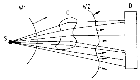
We turn now to practical arrangements -for applying the concept arising from
these determinations. In a first embodiment (Figure 3), there is a source S of
high
spatial coherence and an x-ray imaging detector D, for exainple film,
photostimulable
phosphor plates,,te.g. FujiTM Image Plates),, or a two-dimensional electronic
detector.
Regions of sharp refractive index variation transverse to the direction of
propagation,
CA 02216907 2008-04-09
11
or thickness variation in the direction of propagation, can lead to a
significant change in
the local direction of propagation of the wavefront passing through those
regions. Thus a
spherical wavefront W 1 emanating from the point source S becomes distorted to
W2 on
passing through the object O. By recording the intensity of the wavefront at a
sufficient
distance from the sample, intensity variations due to sharp refractive index
and thickness
variations in the sample may be detected and their location recorded in an
image. This
corresponds to a form of differential phase-contrast imaging. The location of
the
imaging detector is chosen such that the spatial resolution of the detector is
sufficient to
resolve the intensity differences arising from the severe distortions of the
wavefront and
to optimise contrast, as described above, subject to practical considerations.
Typically, the sharp gradients in refractive index or thickness will be imaged
as
sharp losses or rapid variation in intensity at corresponding points in the
image. This
feature of intensity loss or rapid variation at a given point in the image is
essentially
independent of wavelength and can therefore lead to very sharp contrast
variations in the
image even when a polychromatic source is used.
This configuration has the feature that for a circular source distribution,
the
spatial resolution in the image is the same for both directions and is
essentially
determined by the source size. It also has the advantage that considerable
magnification
of the image is possible and so recording media such as FujiTM Image Plates
may be used
which have many desirable properties such as wide dynamic range and high
sensitivity
but not high spatial resolution.
In addition to the source and detector involved in this configuration, a high
resolution angular analyser may be inserted between the sample and the
detector. The
high resolution angular analyser might for example be a suitably curved
crystal in Laue
geometry with curvature chosen for some appropriate characteristic wavelength
of the
source. This variation in the method is aimed at resolving weaker variations
in refractive
index and thickness of the sample than are observable with the first described
configuration.
CA 02216907 2008-04-09
12
It may be noted that a very substantial magnification of the image is possible
so
that very high spatial resolution in the image may be achieved even with much
lower
spatial resolution detectors such as FujiTM Image Plates. Also it may be noted
that
since the method of image formation is essentially independent of x-ray
energy, the
sources can be operated at high tube voltage and so lead to lower absorbed
dose to the
sample, which is important in clinical applications.
Some examples of phase-contrast images recorded using the aforementioned
technique are illustrated in Figures 4 and 5. Figure 4 shows an image of the
edge of
a 10ttm plastic film which is the same as that used in Davis, Gao, Gureyev,
Stevenson
and Wilkins (Phys. Rev. Letters, 1995, Vol. 74, p. 3173) and corresponds to a
pure
phase object. Figure 5 shows images of an air bubble and glass fibres in a
polymer
matrix based on a similar sample to that reported in Davis, Gao, Gureyev,
Stevenson
and Wilkins (Nature Vol. 373 pp. 595-8, 1995) and corresponds to an almost
pure phase
object. In each case clear additional contrast can be seen over that expected
for a
normal absorption-contrast image. In particular, in Figure 4 the edge of the
film is
clearly visible as a black/white contrast feature as also are the edges of the
bubbles and
the fibres. The source used was a nominal 10 m diameter microfocus source
(Kevex
Model PXS) with Cu anode operated at 40 kV. For Figure 4 the source to sample
and
sample to film distances were both 700 mm while for Figure 5 the corresponding
distances were 120 mm and 1000 mm, respectively. It should be noted that
contrast in
the present instances is visible almost entirely due to the high spatial
coherence of the
source. The contrast is primarily an intensity loss contrast and in that sense
resembles
normal absorption but is different in that it represents an intensity loss due
to refractive
scattering (or Fresnel diffraction) at the object boundaries as shown by
equation (8). A
normal fine focus source of diameter 0.1 mm would have a projected size of
approximately the length of the 0.1 mm scale bar shown on the photographs and
so
largely smear out this contrast.
To provide a comparison of phase-contrast imaging as described herein and
standard absorption imaging, the table below sets out the absorption thickness
ta of a
carbon sample required to achieve 65% absorption and the phase thickness tp,
of the
CA 02216907 1997-09-25
WO 96/31098 PCT/AU96/00178
- 13 -
sample required to achieve a phase change in ~ of 27t, for different source
energieE E.
TABLE 1
E keV a.([k) t,( m) tD( .m)
50 0.25 435000 133
12 1 5000 30
1.2 10 4 3
0.25 50 1.3 1.2
The results in the table illustrate how phase-contrast imaging can be used to
image very small objects with high energy sources.
Advantageously, the beam path between sample and detector may involve
evacuated tubes with x-ray transparent windows or similar means to reduce the
effects
of air scattering making sure that their optical quality is such that they do
not have a
detrimental effect on the coherence of the x-ray beam.
The present method should be especially well suited to imaging of such
features
as cracks, voids and delamination effects in various types of materials, since
these
features involve maximum differences in x-ray refractive index and the spatial
variation
can be extremely sharp. To give observable contrast, the source is preferably
of a very
small effective size, say less than of order 20 m, and the detector is
preferably a high
resolution imaging detector such as x-ray film or a two-dimensional electronic
detector,
e.g. a CCD array. The method may also prove useful in significantly enhancing
the
contrast of important features in clinical radiography.
The present application outlines some simplified conditions and configurations
for differential phase-contrast imaging using penetrating radiation such as
hard x-rays,
which are particularly aimed at clinical and industrial applications. These
new
approaches are more closely related to traditional methods used for absorption-
contrast
radiography and should be easier to implement than our earlier described
methods of the
CA 02216907 1997-09-25
WO 96/31098 PCT/AU96/00178
- 14 -
aforementioned W095/05725 and PN5811/95, especially for large areas of
irradiation.
They should also have considerably shorter exposure times for a given source
power
than the earlier monochromatic methods since they may use a very wide spectrum
from
the source.
'
Throughout this specification , unless the context requires otherwise, the
word
"comprise", or variations such as "comprises" or "comprising", will be
understood to
imply the inclusion of a stated integer or group of integers but not the
exclusion of any
other integer or group of integers.