Note: Descriptions are shown in the official language in which they were submitted.
CA 02217349 1997-10-03
WO 96/32202 PCT/US95/04635
METHOD AND APPARATUS FOR COATING A
METAL STRIP AND THE PRODUCT THEREOF
This invention relates to a method and apparatus for applying a polymer
coating on a strip of metal and, in particular, to a method of coating both
sides of an
aluminum strip with thermoplastic resins from extruders and extrusion dies
which are
positioned to deposit the thermoplastic resin on opposite sides of the strip.
The
product of this invention is a strip of metal, such as aluminum, which has
thin ?aolymer
coatings on both sides thereof and which has many applications, but is
particularly
well suited for use in packaging applications such as can ends and can bodies.
It is known to coat metal sheet or strip with thermoplastic resin on one or
both sides to improve the corrosion resistance, formability, appearance or
other
properties of the material. The coating can be applied by a variety of
processes such
as roll coating, reverse roll coating, spraying, electrocoating, powder
coating, and
lamination. The coated strip may be used for applications such as in cans and
can
ends, foil pouches, lidding stock, appliances, electrical devices,
construction,
aerospace or automotive body sheet.
United States Patent No. 5,093,208 to Heyes et al discloses a method for
forming a laminated metal sheet in which a precast thermoplastic polyester
film is
pressed against one or both surfaces of a metal sheet to adhere the film to
the sheet in a
CA 02217349 1997-10-03
WO 96/32202 PCT/LTS95/04635
pressed against one or both surfaces of a metal sheet to adhere the film to
the sheet in a
non-crystalline form. The uncoated sheet of metal is heated to a temperature
above the
melting point of the polyester film and the film is applied to the sheet under
pressure to
form a laminate material. The.Iaminate material is then heated to above the
melting
point of the film to improve the bond of the plastic film to the metal and is
quenched
rapidly to a temperature below the glass transition point of the polyester to
form a
non-crystalline polyester. The quenching is done by passing the laminate
through a
curtain of water.
European Patent Application 0,067,060 in the name of Taiyo Steel Ltd.
discloses a method of producing a coated metal plate by directly extruding a
thermoplastic resin onto the heated surface of the plate. According to that
patent
application, molten resin is applied directly from the extrusion die to the
metal plate
without forming the resin into an independent film. The thickness of the film
can be
Iess than 50 microns and preferably down to 35 to 5 microns. The patent
application
states that since the step of forming an independent film is omitted, the cost
of
producing the coated metal is reduced. Suitable thermoplastic resins used for
coating
of metal surfaces include polyolefins, acrylic resins, polyesters, polyamides,
polyvinylchlorides and many other resins as listed in the published patent
application.
The resin can be coated either as a monolayer or multilayers of the same or
different
resins. The patent application discloses applying the resin on only one side
of the
metal strip.
2
CA 02217349 2006-02-20
52100-3
An improved process is desired for applying a thin
polymer coating on both sides of a metal strip suitable for
use in applications such as packaging. A process is desired
for producing tight adhesion or welding of the polymer to
the strip so that the polymer will not delaminate during
subsequent forming of the strip or use of the products
produced from the strip.
This invention provides a method for coating both
sides of a metal strip with thin thermoplastic polymer resin
to form a coated strip suitable for use in packaging and
other applications.
Accordingly, an aspect of this invention is to
provide an improved method of adhering polyester resin on
both sides of a metal strip.
Thus, in one embodiment of the invention, there is
provided a process for extrusion coating a metal strip to
produce a coated metal strip comprising: providing a strip
of metal in a range of 0.1778 to 0.356 mm thick; heating the
metal strip to at least 121°C; moving the metal strip
through a first pair of rolls and thereafter through a
second pair of rolls each of which pairs include a casting
roll and a backup roll which form a nip for the metal strip
and a polymer resin to move therethrough to adhere the
polymer resin to the metal strip; sequentially extruding the
polymer resin onto one side and the same or a different
polymer resin onto the other side of the heated metal strip
and drawing the extruded polymer resins to reduce their
thicknesses in draw ratios of 1:1 to 200:1 to form coatings
which are partially bonded to the metal strip, the coatings
each having a thickness in a range of 0.0076 to 0.038 mm;
wherein the process is characterized by cooling the casting
3
CA 02217349 2006-02-20
52100-3
rolls to a temperature below the softening point of the
polymer resin; cooling the backup rolls; heating the metal
strip after it has been coated on one side and before
coating it on the other side; heating the strip to at least
the melting point of the polymer after it exits the second
pair of rolls such that the resin bonds to the metal strip;
and cooling the coated metal strip to less than 40°C to
solidify the resin in a non-crystalline form.
Preferably, the extruded polymers are drawn to a
thickness of 0.00254 to 0.127 mm (0.0001 to 0.005 inches),
and more preferably 0.00508 to 0.0508 mm (0.0002 to 0.002
inches) .
In a further preferred embodiment, the rolls are
disposed such that: (I) the strip is moved downwardly
through the nips between the first and second pairs of
rolls; (II) axes of the first pair of rolls are
substantially horizontal and the strip travels in a downward
direction at an angle in a range of 30-70° to horizontal for
feeding into the nip between the rolls in the first pair and
exits them in a downward direction at an angle in a range of
60° to 140° to the direction of travel of the strip into the
rolls; (III) the strip enters the first pair of rolls at an
angle of 45° to horizontal and exits the first pair of rolls
of an angle of 45° to horizontal; (IV) the strip travels in
substantially a straight path from the first pair of rolls
to and through the rolls in the second pair of rolls;
(V) the axes of the rolls in the second pair are disposed in
a plane which is at a 90° angle to the plane of travel of
the strip through the second pair of rolls; or (VI) the
strip travels substantially vertically downwardly through
the nip between the first and second set of rolls.
3a
CA 02217349 2006-02-20
52100-3
In another embodiment of the invention, there is
provided an apparatus for coating both sides of a metal
strip with polymer, comprising: a preheater for heating an
uncoated metal strip; first and second pairs of rolls
located downstream of the preheater, with each pair of rolls
including a casting roll and a backup roll, and with the
casting roll and backup roll for each pair of rolls forming
a nip for moving the metal strip therethrough; first and
second extrusion dies located above, respectively, the first
and second pairs of rolls, with the extrusion dies disposed
to extrude molten polymer webs onto opposite sides of the
metal strip substantially at the roll nips or just ahead of
the roll nips, and with the roll nips configured to press
the polymer webs to the opposite sides of the metal strip to
adhere the polymer webs to the metal strip; a repeater
located between the first and second pairs of rolls for
repeating the metal strip and polymer web deposited thereon
as the metal strip passes between the first and second pairs
of rolls; a postheater located downstream of the first and
second pairs of rolls for heating the strip coated with
polymer and enhancing the bonding between the polymer webs
and the opposite sides of the metal strip; and a quenching
device located downstream of the postheater for quickly
cooling the coated metal strip after the coated metal strip
moves through the postheater.
In a further embodiment of the invention, there is
provided an apparatus for coating both sides of a metal
strip with polymer, comprising: a preheater for heating an
uncoated metal strip; a pair of casting rolls located
downstream of the preheater, with the casting rolls forming
a nip for moving the metal strip therethrough, and with the
casting rolls each having a resilient roll surface for
contacting the metal strip; first and second extrusion dies
3b
CA 02217349 2006-02-20
52100-3
located above, respectively, the casting rolls, with the
extrusion dies disposed to extrude molten polymer webs onto
opposite sides of the metal strip substantially at the nip
formed by the casting rolls or just ahead of the nip, and
with the nip configured to press the polymer webs to the
opposite sides of the metal strip to adhere the polymer webs
to the metal strip; a postheater located downstream of the
casting rolls for heating the metal strip and enhancing the
bonding between the polymer webs and the opposite sides of
the metal strip; and a quenching device located downstream
of the postheater for quickly cooling the coated metal strip
after the coated metal strip moves through the postheater.
In a still further embodiment of the invention,
there is provided an apparatus for coating both sides of a
metal strip with polymer, comprising: a preheater for
heating an uncoated metal strip; a pair of applicator rolls
located downstream of the preheater, with the applicator
rolls forming a roll nip for moving the metal strip
therethrough; a pair of pinning and drawing rolls located
adjacent, respectively, the applicator rolls; first and
second extrusion dies located above, respectively, the
pinning and drawing rolls, with the extrusion dies disposed
to extrude molten polymer webs onto the roll surfaces of the
pinning and drawing rolls, with the pinning and drawing
rolls operable to rotate at a higher surface velocity than
the velocity of the molten polymer webs exiting the
extrusion dies, thereby drawing the polymer webs to a
reduced thickness prior to passing the polymer webs to the
applicator rolls, and with the roll nip formed by the
applicator rolls configured to press the polymer webs to
opposite sides of the metal strip to adhere the polymer webs
to the metal strip; a postheater located downstream of the
applicator rolls for heating the metal strip and enhancing
3c
CA 02217349 2006-02-20
52100-3
the bonding between the polymer webs and the opposite sides
of the metal strip; and a quenching device located
downstream of the postheater for quickly cooling the coated
metal strip after the coated metal strip moves through the
postheater.
The above and other aspects and advantages of this
invention will be more fully understood and appreciated with
reference to the following description and the drawings
attached hereto.
Figure 1 is a schematic, side elevational view of
one embodiment of a system of this invention.
Figure 2 is a schematic, side elevational view of
a portion of another embodiment of this invention.
Figures 3 and 4 are schematic, side elevational
views of further embodiments of this invention.
3d
CA 02217349 1997-10-03
w0 96/32202 PCTlLTS95/04635
Figure 5 is a partial cross section of the strip and extrusion dies of
Figure 4 greatly enlarged to show the application of the resin to the strip.
Figures 6 through 14 are schematic, side elevational views of further
embodiments of this invention.
The drawings appended hereto illustrate systems for coating-both sides
of a strip of metal as it travels from a first coil to a second coil on which
the metal is
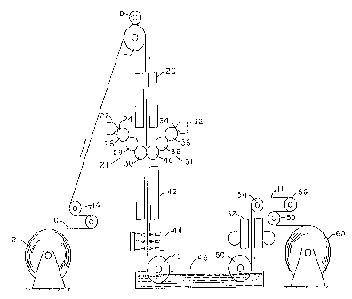
wound after it has been coated. Referring in particular to Figure 1, a strip
10 of
aluminum alloy is unwound from coil 12, moves around tension rollers 14,
travels
vertically upward over a roll 16 and then downward from roll 16 through the
coating
apparatus. A back-up roll 18 may be used to maintain the metal strip 10 in a
flat
condition as it moves over support roll 16.
As the strip 10 moves downwardly from roll 16, it is first heated by
heater 20 to a temperature close to or above the melting point of the polymer
to be
applied thereto. In the embodiment illustrated in Figure 1, the heater is an
induction
heater, but other heaters or preconditioners such as flame treatment,
infrared, plasma
and/or corona discharge may also be employed either singularly or in
combination.
Flame heaters can be used in tandem (one on each side) or on one side only to
enhance
performance (improved bonding as well as heating). The coil 12 may also be
used,
which is still hot from the prior processing, such as rolling or heat
treatment, to
minimize or even eliminate the need for heating by heater 20. A typical
temperature to
4
CA 02217349 1997-10-03
WO 96/32202 PCT/US95/04635
which the metal is heated, prior to appIicaiton of the thermoplastic material,
in the
range of about 121 °-260°C (250°-500°F) depending
on a number of factors, primarily
the particular polymer that is to be applied to the strip.
Two separate extrusion coating systems 21 and 31 are provided for
applying thin webs of thermoplastic polymer such as polyester resin to the two
surfaces of the heated web. The systems 21, 31 are disposed just below the
induction
heater 20. The extrusion coating systems 21, 31 each include an extruder for
delivering a molten polymer extrudate through a sheet die 22, 32 having a
narrow exit
slit to produce a thin web of extrudate 24, 34 which is passed through a three-
roll
stack. Alternatively, one extruder may feed both extrusion dies via transfer
pipes or
other manifolding.
The first rolls 26, 36 of the systems 21, 31 are pinning and drawing rolls
which are maintained at a temperature which will promote sticking or clinging
of the
polymer extrudate to the polished surface of the roll. A typical temperature
for this
purpose is in the range of about 120° to 180°C (248°-
356°F), depending on the resin
being used. The surface speed of the rolls 26, 36 is substantially faster than
the speed
of the extrudate exiting the die 22, 32, thus drawing the polymer to a reduced
thickness. Typical speed ratios of drawing velocity to extrudate velocities
range from
about 5:1 to 40:1. The resin from the extruder is typically approximately
O.I27-0.635
mm (0.005-0.025 inch) thick and is drawn to a reduced thickness of
approximately
0.0076-0.038 mm (0.0003-0.0015 inch) thick.
CA 02217349 1997-10-03
WO 96/32202 PCT/US95/04635
The second rolls 28, 38 are cooler than the first rolls and are designed to
polish and cool the extrudate by rolling contact between the rolls and the
extrudate.
The second rolls 28, 38 also transfer the extrudate to the third rolls which
are the
applicator rolls. The third rolls 30, 40 may be tension loaded using springs,
hydraulics
pneumatics, or the like and preferably have resilient (such as high
temperature resistant
elastomers) exterior surfaces, or roll shells, to press the semi-cooled
extrudates against
the heated metal web or strip 10. The third rolls 30, 40 of the two extrusion
sets
support opposite sides of the strip 10 against the pressure or force of each
other so that
the semi-cooled extrudates 24, 34 can be pressed against the strip under the
pressure of
such third rolls 30, 40.
The coated strip of metal 11 continues its vertical downward travel past
or through a second heater 42 which uniformly heats the metal or the plastic,
or both
the metal and the plastic, especially at the interface therebetween to a
temperature that
will consummate bonding of the polymer to the metal strip without
substantially
reducing or other~~ise deleteriously affecting the desired properties of the
metal strip or
the plastic coating thereon. The desired temperature will depend on the
particular
polymeric material which is being applied as a coating but is somewhere in the
range
of approximately 200° to 260°C (392-500°F). The second
heater 42 is preferably an
induction type heater, which is well known in the art. Alternatively, the
heater 42
could be a convection oven or an infrared heater.
6
CA 02217349 1997-10-03
WO 96/32202 PCT/US95/04635
Upon exit from the second heater 42, and while continuing in a vertical
downwardly direction, the coated strip 11 is rapidly cooled as by a water
spray 44, a
water curtain, or other suitable cooling means. Such cooling must lower the
temperature of the composite structure to a low enough temperature to allow
turning
the coated strip around rollers without deleteriously affecting the coating or
the metal.
In a preferred method of coating an aluminum alloy, such as alloy 3004, can
sheet with
polyester resin, the composite structure is preferably cooled to below
approximately
40°C ( 104°F) before it contacts roller 48. In such a preferred
embodiment, cooling is
fast enough that the polyester coating on it is solidified in a substantially
non-
crystalline form. The speed of cooling to accomplish this will depend on the
polyester.
The rate of cooling can be controlled by controlling the temperature and
volume rate of
flow of the cooling water against the coated strip.
In the embodiment illustrated in Figure 1, the coated strip moves through
a bath 46, such as a water bath, and around rollers 48 and 50 on opposite ends
of the
bath before the coating is dried. The water bath completes the cooling
process.
From the water bath 46, the coated strip 11 preferably moves vertically
upwardly through a drying system 52 to remove residual moisture from the strip
before
rewinding. The drying system 52 may typically comprise warm air blowers. The
composite strip next moves over rollers 54, 56 and 58 and onto a rewinder 60.
The
system may include accumulators, not shown, to accommodate roll changes or
coil
changes and may also include means for leveling the metal after it has been
coated.
7
CA 02217349 1997-10-03
WO 96/32202 PCTlUS95/04635
The system also preferably includes trimmers, not shown, for trimming the
edges of
the coated metal web 11 or to remove any polymer that extends past the edges
of the
metal. The trimmers may be located at various points along the path of the
strip such
as immediately after the polymer resin is applied to the strip, after the
spray cooler, or
after the drying system.
The aluminum strip that is coated by this invention may be of a variety
of alloys and tempers depending on the use which is to be made of the strip.
Some
typical aluminum alloys suitable to be forming can ends and can bodies include
Aluminum Association alloys 5042, 5182 and 3004 in intermediate to hard temprs
including H-14, H-19 and H-39 tempers, among others. The metal strip is
typically
O.I778-0.356 mm (0.007 to 0.014 inch) thick.
In accordance with this invention, a variety of thermoplastic polymers
such as a polyester can be used to coat an aluminum strip which is designed
for use in
packaging such as cans or can ends. A preferred polyester resin is a high melt
viscosity (HMV) resin of the type that has heretofore been used to coat
ovenable metal
trays, liquid foil packaging and heat sealable foil packaging. SELAR~, PT8307
HMV
copolymer resin sold by E. I. Du Pont de Nemours Company is an example of a
high
performance polyester resin suitable for use in this invention. Such copolymer
can
also be blended with other thermoplastic polyesters such as bottle grade
polyesters
having intrinsic viscosities~of about 0.72 IV and above. For example, a blend
of
SELAR~, PT8307 HMV copolymer with T89 PET sold by Hoescht-Celanese may
8
CA 02217349 1997-10-03
WO 96/32202 PCT/US95/04635
provide improved performance for aluminum strip coated in accordance with this
invention for use in making products such as ends for beverage cans. Other
thermoplastic polymers suitable for use in this application include
polypropylene,
polyethylene, polyamides (nylon), polyimides, polycarbonates and polyvinyl
chloride
(PVC), among others.
Figure 2 shows a portion of an alternative embodiment of a system for
practice of the present invention. In this system, the metal strip 70 is
coated on both
sides as the strip preferably moves vertically upwardly instead of vertically
downwardly as in Figure 1. The metal strip 70 moves around an infeed roll 72
and
vertically upwardly from that roll through a pre-heater 74 such as an
induction heating
system. The strip then moves through an optional flame treater 76 and between
the
opposed extrusion systems 78, 80 for coating both sides of the strip. The
flame treater
enhances the receptivity of the strip to bonding by the resin coating.
The extrusion coating systems 78, 80 in Figure 2 are similar to that of
Figure 1 except that the systems 78, 80 each include only two rolls rather
than three
rolls as in Figure 1. The surface speed of the pinning and drawing rolls 82,
84 is
several times faster than the exit speed of the polymer from the extruder dies
90, 92 so
as to draw and thin the extrudate as in the system of Figure 1. Rolls 86, 88,
which are
cooler than rolls 82, 84, receive the extrudate from rolls 82, 84 and apply it
to the strip
70.
9
CA 02217349 1997-10-03
WO 96/32202 PCT/US95/04635
After the strip 70 has been coated on both sides, the strip continues to
move vertically upwardly into an insulated chamber 94 which contains a cooling
and a
turning roll 96 for cooling the strip and redirecting it vertically
downwardly. The
chamber 94 is preferably insulated for accurate temperature control of the
strip as it
moves over the cooling and turning roll 96. The roll 96 preferably has an
outside shell
diameter of at Ieast approximately three feet. The roll's large diameter
minimizes
stressing of the metal due to curvature effects. The temperature of roll 96
and strip 71
is controlled by fluid 91 in an annular chamber 93 between the roll's outer
shell 97 and
an inner shell 95. The annular chamber 93 is preferably not filled to capacity
so as to
minimize the inertia effects (provides viscous damping) and enable speed
control and
tracking.
The composite coated strip 71 moves vertically downwardly from the
turning and cooling roll 96 through a post-heater 98 which heats the composite
strip to
approximately 204-260°C (400-500°F) to enhance bonding of the
polymer such as
polyester resin to the strip as in the embodiment of Figure 1. The heater 98
may be a
conventional induction heater, convection oven or infrared heater. The
composite strip
71 moves from the heater 98, through cooling or quenching means not shown, to
a
second cooling and turning roll 99 and from that roll to a rewind roll not
shown. Roll
99 is similar in design and dimensions to roll 96 described above.
Figure 3 is a schematic of another embodiment of this invention in which
cleaned, room temperature, conditioned sheet stock 100 is unwound from an
unwinder
CA 02217349 1997-10-03
w0 96/32202 PCTlUS95/04635
102 and fed upwardly over a draw roll set 104 consisting of roll 103 and an
optional
back-up roll 105 at the top of the processing stack. Accumulators, not shown,
may be
included to accommodate coil changes on the unwinder 102.
From the draw roll set 104, the web 100 travels in a vertical and
downward direction, and is preferably slanted about 30-45 degrees from the
vertical.
Such slant facilitates downstream extrusion coating and machinery arrangement.
The
web 100 passes through a pre-heater 106, wherein an induction field is
generated to
uniformly heat the metal to a temperature that will enhance downstream "green
peel"
strength of the bonded polymer to the strip without substantially reducing or
otherwise
deleteriously affecting the desired metal properties. As used herein, "green
peel"
strength means that the polymer is adhered to the metal strip with sufficient
holding
power that the polymer will not delaminate from the strip during subsequent
processing. The desired temperature should be in the range of approximately
204°-260°C (400-500°F), and preferably approximately
215°-246°C (425°-475°F)
when applying polyester.
The pre-heated web 100 continues in a downwardly slanted direction and
passes through an optional flame surface treater 108. The flame treater may
reduce the
surface of the pre-heated metal to eliminate, minimize or enhance oxides, and
thereby
enhance adhesion of a polymer which is subsequently applied to it.
The heated and treated web 100 next enters the first of two extrusion
coating stations. An extruder, not shown, melt-plasticizes a PET polymer or
other
11
CA 02217349 1997-10-03
WO 96/32202 PCT/L1S95104635
thermoplastic resin and delivers it through a sheet die 1 I O which is
positioned either
vertically or obliquely from vertical and which has a narrow exit slit. The
slit is set to
produce a back-pressure to the extruder that enables spreading of an extrudate
112 to a
width at least as wide as the width of strip 100. The slit may have a width
less than
the width of the strip 100 depending on several factors such as the nature and
thickness
of the polymer resin, the relative speeds of the extruder and metal strip and
the shape
of the die, the shape of the extrudate film, among other factors. The
extrudate 112 is
drawn into a roll stack 114 to reduce its thickness to the final thickness for
application
to the web. The draw thickness ratio should be approximately 10-25:1,
depending on
the extruded polymer.
The two-roll stack 114 is disposed such that a plane through the
centerline of the Tolls is slanted approximately 30 degrees from horizontal.
The
"inside" or turning roll 116 preferably has a resilient surface made of high
temperature-
resistant elastomer and is internally and/or externally cooled to minimize
deterioration
of the elastomer.
The outside or pressure roll 118 is chrome-plated steel, polished, and
preferably maintained at a temperature below about 150°F or 66°C
(for polyester)
which is below the "stickiness" point of the molten polymer which applies line
pressure to the polymer as it is applied to the strip material. This enhances
adhesion of
the polymer to the metal 100 as well as improves surface appearance. The
surface
speed of the rolls 116, 118 is approximately 10 times faster than the
extrudate's exit
12
CA 02217349 1997-10-03
WO 96/32202 PC'T/US95/04635
speed from the extrusion die 110, thus drawing the polymer onto the web 100 to
its
desired thickness in a range of approximately 0.00762 mm to 0.02032 mm (0.3-
0.8
mils) and preferably about 0.01016 mm (0.4 mils). The two-roll stack 114 coats
the
first side of the web 100 with adequate "green peel" strength to avoid
separation of the
polymer from the metal during the subsequent processing.
The single-side coated web 101 next exits the stack 1 I4 and turns
approximately 60 degrees (as a result of the preferred positioning of the
second
extrusion station) over the elastomer coated roll 1 I 6 to slant the web
downward : ~0-45
degrees from vertical (approximately 60 degrees from the entry position into
the first
stack). The pre-heated and single-side coated web 101 continues in a 30-45
degree
slanted and downward direction, may pass through an optional second (and
possibly
larger) flame or other type of boost heater 120, wherein the surface of the
pre-heated
metal is treated to eliminate/minimize oxides on the second surface and
enhance
adhesion of the polymer, as well as to provide any needed temperature "boost"
to
achieve optimum bonding conditions.
The pre-heated and pre-treated web l0I next enters the second of the
two extrusion coating stations to coat the opposite side of the web than was
coated by
the first coating station. The extruder performance requirements, arrangement,
and
process for the second extruder are identical to the first extruder. The
melted extrudate
122 from extrusion die 124 is passed into the nip of a two-roll stack 126
having an
arrangement in which a plane through the centerlines of the rolls 128, 130 is
inclined
13
CA 02217349 1997-10-03
WO 96/32202 PCT/LTS95/04635
approximately 30-45 degrees from the horizontal (45-60 degrees from the
centerline
position of the first stack 1 14).
The geometries, arrangement, performance, and functions of the rolls
128, 130 are identical to that of the first stack 114_ The second side of the
pre-heated
web 101 is coated with extrudate 122 to produce adequate "green peel"
strength, as
described above for the first side. The double-side coated web 103 next exits
the stack
126 and is preferably turned approximately 45-90 degrees over the rubber
coated roll
to achieve a preferred positioning for the induction bonding heater 132 at
approximately 30-45 degrees from vertical in a downward direction.
The now-coated web 103 continues in a slanted and downward direction
and passes through a second heater 132, preferably an induction heater, to
uniformly
heat the metal/plastic interface to a temperature that will consummate a bond
of the
plastic to the metal ~'eb without substantially reducing or otherwise
deleteriously
affecting the desired metal properties or the plastic. The temperature is
preferably
approximately 400-550°F (204-228°C) and preferably about 425-
475°F (215-246°C)
for polyester.
Upon exit from the induction heater 132, and while continuing in a
slanted and downward direction, spray nozzles 134 (or other suitable devices)
cool the
composite structure to a temperature low enough to allow turning around roller
I36
without deleteriously affecting the composite material's ultimate end-use
performance
14
CA 02217349 1997-10-03
WO 96132202 PCT%US95/04635
requirements. The semi-cooled composite 103 is turned and passed through a
horizontal water bath 138 to complete the cooling process.
A drying system 140 is used after the composite 103 leaves the bath 138
to remove residual moisture before rewinding. Leveling is performed to remove
stresses produced by the turning or bending of the metal strip 100 over the
rolls. The
completed material 103 is then rewound by rewinder 142. Accumulators, not
shown,
can be used to accommodate roll changes and coil changes on the rewinder 142.
Figures 4 and 5 illustrate a further embodiment of this invention in which
the metal strip 150 is moved vertically upwardly during the coating process
and in
which the extrusion dies 152, 154 apply the molten resin directly against the
opposite
sides of the strip. The system of Figure 4 includes an unwinder 156 from which
strip
150 travels upwardly through an induction pre-heater 158, and then between two
extrusion dies 152, 154. The dies 152, 154 are fed by conventional extruders,
not
shown.
Figure 5 is a greatly enlarged showing of the dies 152, 154 as they apply
extrudate 160, 162 directly to the metal strip 150. The die orifices are
positioned close
to the strip so that the force of the extrudate issuing from the dies is
applied against the
strip. The dies are positioned within about 5 to 20 mm of the strip, and
preferably less
than 10 mm from the strip. The metal strip 150 travels approximately I O-20
times
faster than does the extrudate issuing from the dies 152, 154 so the extrudate
is drawn
and reduced in thickness by pull of the strip on the extrudate. The extrudate
may be in
CA 02217349 1997-10-03
WO 96/32202 PCT/US95/04635
the range of 0.0127 to 0.0508 mm (0.(K>n5-0.002 inch) thick on each surface of
the
step.
The dies 152, 154 are preferably directly opposed to each other on
opposite faces of the strip 150 so the pressure of the extrudate from opposite
sides of
the strip will center the strip between the dies. The molten polymer impinges
upon the
surface of the metal strip almost immediately after the extrudate exits the
dies, so the
polymer does not cool or neck-in before it is applied to the strip. This helps
to ensure
the application of uniform coatings of the resin on both faces of the strip.
From the extrusion dies 152, I54, the coated strip 1 S 1 preferably moves
through an induction type post-heater 164 which heats the composite strip to
above the
melting point of the polyester resin to enhance bonding of the resin to the
strip. The
composite strip is then quickly cooled by means not shown and travels over
rolls 166
and 168 to a recoiler 170.
Figures 6 through 14 show alternative embodiments of this invention for
coating both faces of strip metal such as aluminum, steel, copper, metal
laminates or
the like. These embodiments all include means for preheating the metal strip,
first and
second extrusion coating apparatus including dies and application rolls, means
for
post-heating the strip after it has been coated on both faces, and means for
cooling the
strip. The systems may also optionally include means for reheating the strip
between
the first and second coating apparatus. The systems all include an extruder or
extruders for feeding polymer extrudate to the dies. Each of the first and
second
16
CA 02217349 2005-04-15
50989-59
extrusion coating apparatus in the systems includes a
casting roll which contacts the web of polymer extrudate to
press it against the metal strip and a back-up roll which
supports the strip metal and provides a roll nip for
pressing the strip metal and web of polymer together to
adhere the polymer to the face of the strip. The systems
may optionally include a support roll for one or both
back-up rolls to support the back-up roll and help to cool
it.
The preheater, repeaters and postheaters in these
systems can be of a variety of forms such as induction,
flame, infrared, radiant, electric, fossil fuel convection
furnaces, heating rolls or any combination of such devices.
The strip can also be preheated in coil form or from prior
processing of the strip to either supplement or replace a
preheat device. A preferred form of heater is a TFX~
induction heater that is available from Davy McKee (Poole)
Ltd: of Poole, England.
The dies in these systems are positioned within
approximately 4-12 inches (10.2-30.5 cm; i.e., 101.60 to
304.80 mm), and more preferably about 6-8 inches or
15.2-20.3 cm (depending on the die and roll sizes), of the
die nip between each pair or rolls. The extruded webs of
polymer preferably contact the metal strip and the casting
roll substantially simultaneously at the roll nip or contact
the metal strip just ahead of the roll nip. Alternatively,
the extruded webs can contact the casting roll a few degrees
of rotation before entering the roll nip. Such contact of
the casting roll before the roll nip should not be more than
a few degrees of rotation of the roll, such as about 0-25°,
to
17
CA 02217349 1997-10-03
WO 96/32202 ~ PCTILTS95/04635
minimize cooling of the polymer before the polymer contacts the metal strip at
the roll
nip.
The extruded webs of polymer may be approximately 0.005 to 0.030
(O.I27-0.254 mm)inches thick and are preferably drawn downwardly by the metal
strip
and rolls to reduce the thicknesses of the webs. The draw ratio may be in a
range of
about 1:1 to 200:1, and more preferably about 10:I to 40:1. As used herein,
draw ratio
means the ratio of the thickness of the web as extruded to the thickness of
the web as
applied to the strip metal. The draw ratio is generally determined by the
difference
between the rate of extrusion from the dies and the speed of the strip metal
being
coated. For example, a draw ratio of 20:1 generally means that the strip is
moving
about 20 times faster than the speed of the web as it exits the die opening.
Techniques
for drawing and thinning extruded webs of polymer are well known in the art.
For some systems, it may be desirable to provide supplemental means in
advance of the roll pairs to pin or apply the extruded webs against the face
of the strip
metal. Supplemental pinning means can include air knives, electrostatic
devices, and
vacuum pinning means, among others. The webs may be cast to be entirely on the
strip metal or may be cast wider than the metal and later trimmed to remove
excess
coating.
For most applications, the casting roll is preferably a hard metal roll
having a chrome plating, chrome oxide, aluminum oxide or other hard metal roll
surface on it. Such roll surfaces may be polished or textured. The casting
roll is
I8
CA 02217349 1997-10-03
WO 96/32202 PCT/US95I04635
preferably cooled to below the stickiness or softening point of the polymer so
the
polymer will not stick to the roll. The back-up roll for most applications
preferably
has a resilient outer surface portion made of silicone rubber, polyurethane,
chlorotrifluorethylene polymers such as VITON~ or KEL-F~', tetrafluoroethylene
fluorocarbon polymers such as TEFLON~, or other high temperature resistant
synthetic rubber or elastomeric material, or combinations of such materials.
VITON~,
KEL-F~ and TEFLON~ are trademarks of E.I. Du Pont de Nemours Company. The
outer surface of such elastomeric material preferably has a Durometer hardness
of
approximately 75-85 shore A. For some applications, it may be desirable to
have a
hard surface such as TEFLON~, VITON~ or KEL-F~' elastomers over a more
resilient
material such as natural or synthetic rubber to provide a hard wear surface
and
appropriate compressibility. Both the casting roll and back-up rill should
have
relatively smooth surfaces in a ranje of about 2-20 root-mean-square (lTns).
For some
applications, the casting roll may alternatively have a hard high temperature
resistant
synthetic rubber surface as described for the backup roll.
The casting roll and back-up roll are pressed against the strip metal and
polymer web as the strip and web travel through the roll nip to thereby adhere
the web
to the strip. Pressing the rolls toward one another presses the metal strip
against the
resilient material on the back-up roll and helps to assure that the polymer
web is
pressed against the metal strip across the full extent of the roll nip with no
gaps in the
contact. The force across the roll nip may vary slightly due to misalignment
of the
19
CA 02217349 1997-10-03
WO 96/32202 PCT/US95/04635
rolls or small variations in the strip thickness, and roll finishes among
other things, but
must not have gaps of inadequate roll force. Pressing the rolls together
compresses the
elastomeric material on the backup and/or casting rolls to produce a band of
contact at
the roll nip along the length of the rolls which is believed to accommodate
any errors
in alignments of the rolls of out-of flatness of the metal strip and provide
more
uniform distribution of the force of the polymer webs) against the metal strip
for
better coating uniformity and bonding. Apparatus for providing the force for
pressing
the rolls against one another and regulating or adjusting the force are well
known in
the art and include pneumatic and hydraulic cylinders, jacks and screws which
act on
the rolls.
The polymer coatings applied by this invention may be any of a variety
of resins as described above with respect to Figure 1. The resins are
preferably
essentially I00% polymer with little or no solvents in them that can
volatilize. The
same or different resins may be applied on the opposite sides of the strip,
and one or
both coatings may contain a pigment or other additive. The strip metal is
preferably an
intermediate to hard temper aluminum alloy having a thickness of about 0.007
to 0.014
inch (0.1778-0.3556 mm) as described about with respect to Figure l, but can
also be
other metals such as steel or copper or laminates. The strip is preferably pre-
cleaned
and may be pre-treated as by anodizing or conversion coating (preferably non-
chrome)
or surface roughening to improve performance and improve adherence of polymer
coatings to the strip. For example, aluminum strip can be cleaned and treated
with
CA 02217349 1997-10-03
WO 96/32202 PCT/LTS95i04635
titanium or zirconium phosphate treatments, silicate treatment or BETZ
METCHEM'~
conversion coatings. BETZ METCHEM~' is a registered trademark of Betz
Laboratories, Inc., of Horsham, Pennsylvania. The strip may also be precoated
on one
or both sides with organic coatings or finishes to enhance bonding of the
polymer to
strap.
the '
In the operation of these systems, the metal strip is moved through the
system at speeds in a range of about 300-1500 feet per minute (fpm) or about
90-450
meters per minute (mpm) and preferably about 600-1200 fpm (180-360 mpm).
H:~gher
speeds obviously increase productivity and also reduce the time period
(residence
time) during which the metal is at elevated temperatures. Shorter residence
times are
sometimes preferred to minimize reduction in metal properties.
Referring now to Figure 6, the coating system is illustrated as including a
roll 172 over which metal strip 174 travels to be fed into and through a
preheat device
173 such as an induction heater which heats the strip to a temperature in a
range of
about 250-550°F (121-288°C) depending on the metal and temper of
the strip, the
desired properties of the strip after coating, and the polymers to be applied,
among
other factors. For aluminum strip to be coated by polyester resin for use of
the coated
strip in packaging applications, a more preferred preheating range is
approximately
400 to 550°F (204-288°C). The preheat temperature, as well as
the reheat and
postheat temperatures, must not be so high as to deleteriously affect the
desired
properties of the strip metal or the polymer coatings on the strip.
21
CA 02217349 1997-10-03
WO 96/32202 PCT/US95/04635
The preheated strip 174 is coated sequentially on opposite faces by two
extrusion dies 176, 178 and two pairs of rolls 180, 182 and 184, 186. One or
two
extruders, not shown, feed molten polymer resin to the extrusion dies 176,
178. The
resin can have a temperature in a range of about 350 to 650°F (177-
343°C) as fed to
the dies 176, 178, and the dies are preferably heated as by electrical
resistance means
to maintain the resin at the desired temperature. The extrusion dies 176, 178
have
elongated, narrow die openings therein approximately corresponding in length
to the
width of the strip 174 which is being coated, which may be about 10-85 inches
(25.4-
215.9 cm) or more. The length of the die opening is preferably at least as
wide or
wider than the width of the strip 174 so the web of polymer extruded from each
die
will fully cover the strip. The die openings are long and narrow in order to
extrude
thin webs. The die openings may be up to 0.030 inch (0.762 mm), and preferably
are
in a range of approximately 0.005 to 0.015 inches (O.I27-0.381 mm). The dies
are
generally conventional dies and are available from a variety of vendors. The
dies 176
and 178 exude thin webs 188 and 190 which are applied against opposite sides
of the
strip 174 by the roll pairs 180, 182 and 184, 186.
In the first roll pair, roll 182 is the casting roll which contacts the web
188 of polymer issuing from die 176, and roll I80 is a back-up roll which
supports the
strip 174 against the casting roll. As stated above, the casting roll 182 is
preferably a
hard metal roll, and the back-up roll I80 preferably has a resilient outer
roll surface or
shell such as a silicone rubber outer layer on it. Both the rolls 180, 182 are
preferably
22
CA 02217349 1997-10-03
WO 96/32202 PCT/US95/04635
cooled by coolant such as water which is circulated through them. The casting
roll is
cooled to less than about 150°F (66°C) so the web of polymer
will not stick to it. The
back-up roll 180 is preferably internally and/or externally cooled to minimize
heat
damage to the resilient layer on the roll. A support roll 181 may be
optionally
provided to support the back-up roll 180 and help cool it.
As shown, the rolls 180, 182 may be positioned parallel with their axes
side-by-side in a substantially horizontal plane so the strip metal 174 and
polymer web
188 can be fed downwardly into the nip between the rolls and out through the
bottom
of the roll nip. The strip 174 may follow the outer surface of the back-up
roll around
approximately a 0 to 120° arc of the roll before the strip leaves the
roll surface to
travel to the reheater 192. The polymer web 188 on the strip metal 174
preferably has
minimal contact with the casting roll 182 in order to minimize possible
sticking or
adverse effects on the web by the roll. This minimization of contact is
especially
applicable for polyester resins, whereas more contact and greater cooling of
the resin
by the casting roll is desirable for polypropylene resins (See Figure 14). The
rolls 180,
I 82 are pressed together with a force of about 50-300 pounds per linear inch
(pli) or
about 9.0-53,7 kg per cm, preferably about 120-180 pli (21.5-322 kg per cm),
and
more preferably about 150 pli (26.9 kg/cm) along the length of the roll nip.
This force
causes the resilient compressible outer portion of the back-up roll 180 to be
deformed
or impressed slightly to insure that there are,no gaps in the force of the
rolls against the
metal strip across the full length of the roll nip and provides a measure of
forgiving or
23
CA 02217349 1997-10-03
WO 96/32202 PCT/US95/04635
accommodation to misalignment of the rolls or out-of-flatness of the sheet
material_
But this force does not reduce the gauge of the polymer or the materials. As
stated
above, this compression of the compressible layer on the backup roll 180
produces a
narrow band of contact between the rolls 180, 182 and the strip 174 at the
roll nip.
Depending on the amount of force pressing the rolls together and the
resiliency of the
support roll 180, among other factors, a typical band of contact may be about
1/4 to 1
inch (0.64-2.54 cm) wide and typically about 3/4 inch (1.9 cm) wide.
After the strip I74 has been coated on one face, it may optionally be
reheated as, for example, with an induction heater 192 or the like. The strip
may be
reheated to a temperature in the range of about 250 to 550°F (120-
288°C), depending
on the polymer being applied, and more preferably to about 400 to 550°F
(204-288°C)
for polyester coatings. For some applications and some polymers, it may not be
necessary to reheat the strip 174 before it is coated on its opposite face.
From the reheater 192, the strip I 74 travels to the second extrusion die
178 and roll pair 184, 186 and optional cooling roll 187 for a second polymer
web
190 to be applied to the opposite side of the strip from that coated by the
first web 188.
The distance from the exit of the first nip to the second nip is preferably
kept short to
control the heat loss from the metal as it travels between the two roll nips.
The second
die 178 and second roll pair I 84, 186 are similar to the first die I76 and
roll pair 180,
182 except that the rolls are reversed, the second casting roll is on the
opposite side of
the strip from the first casting roll, the axes of the rolls are in a
different plane, and the
24
CA 02217349 1997-10-03
WO 96/32202 PCT/ITS95104635
second die 178 is in a different orientation. In order for the strip 174 to
pass in a
substantially straight line through the second die nip, the plane through the
axes of the
rolls 184, 186 is substantially perpendicular to the plane of the strip moving
through
the die nip and at an angle to vertical. The strip 174 therefore has minimal
contact
with rolls 184, 186 except for the narrow band of contact produced by the
resilient
deformation of the resilient material of the outer portion on the back-up roll
186. As
stated above, this minimization of contact of the rolls 184, 186 against the
polymer on
the strip 174 is believed to be helpful in enhancing the quality and
performance of the
final coated product for some polyester resins. For other polymers such as
polypropylene, a substantial roll wrap and cooling of the polymer is preferred
before
the coated strip departs from the roll.
As with the first set of rolls, the second set of rolls 184, 186 must be
pressed against the metal strip 174 and the polymer web with sufficient force
to ensure
that the polymer web 190 is pressed tightly against the strip across the full
width of the
roll nip. The force between the second set of rolls 184, 186 should be in a
range of
approximately 50-300 pli (9.0-53.7 kg/cm), and preferably about 120-180 (21.5-
32.2
kg/cm).
After the strip 174 has been coated on both sides or faces with the
polymer webs 188, 190, the fully coated strip travels through a post-heater
I94 and
through a system for cooling the coated strip. Although not essential to the
invention,
it is believed to be desirable to minimize contact of the coated strip by
rolls or other
CA 02217349 1997-10-03
R'O 96/32202 PCT/US95/04635
mechanical devices between the coating rolls 184, I 86 and when the polymer
has been
solidified by cooling. For example, it is desirable for the strip I74 to
travel in a
substantially straight line from rolls 184, 186 through a post-heater 194 and
through
means, not shown, for at least partially cooling the strip to at least below
the melting
point of the polymer coatings on the strip. In this way, contact with the
polymer on
the strip with rolls or the like is avoided before the polymer is solidified,
and the
coatings are not as likely to be adversely affected by rolls or the like.
The post-heater 194 is preferably an induction heater, infrared heater,
convection oven or a combination of two or all three that can quickly heat the
resin on
the sheet to at least about the softening temperature and preferably above the
melting
point of the polymers. It is important that such heating not be so high as to
significantly deleteriously affect the properties of the metal in the strip or
the polymer
coatings on the strip. Heating the polymers to at least approximately their
melting
points may be desirable to cause the polymers to flow and thereby heal any
blemishes
and/or smooth any unevenness of the coatings on the strip.
After the strip has been post-heated, it is cooled quickly to solidify the
coating in a substantially non-crystalline form. It may be desirable to first
partially
cool the strip with air or other gas to below the melting point of the polymer
and then
to quench the partially cooled strip with water sprays or a water bath.
Partially cooling
the strip with air is believed to minimize possible adverse effects that water
might have
on polymer that is still melted or molten. As used herein, "quickly cooling"
means that
26
CA 02217349 1997-10-03
WO 96/32202 PCT/US95104635
the polymer coatings are cooled promptly after the coated strip exits the
postheater as
the strip is traveling at about 300-1500 fpm, and preferably about 600-1200
fpm. The
cooling or quench unit is positioned within a few feet, such as about 5-50
feet, of the
postheater so the polymer coatings are preferably solidified less than about
10 seconds
and more preferably less than about one second after the coated strip exits
the
postheater.
After the strip has been cooled, it can be further processed as by
trimming the edges, slitting, leveling, winding on a coil or made into
products such as
can ends or can bodies with or.without being rewound.
Figure 7 shows an alternative system similar to the system shown in
Figure 6 except that the upper pair of rolls 202, 204 is positioned with the
axes of the
rolls disposed in a plane which is perpendicular to the strip 196 passing
through the
roll nip. Cooling rolls, not shown, may be added to help cool rolls 202, 208
and 212.
In this system, there is minimal contact of the strip against the back-up roll
so there is
less heat transfer from the strip to the back-up roll and less heat damage to
the resilient
outer portion of the back-up roll 202. This also means less cooling of the
strip metal,
which may obviate any need to boost or reheat the strip before it is coated on
the
inverse side. If reheating is desired, the one-sided coated strip has its
direction turned
by roll 208 and is passed through a boost heater 210. The strip then has its
inverse
side coated by die 216 and rolls 212, 214. The fully coated strip is then post
heated
27
CA 02217349 1997-10-03
WO 96/32202 PCT/US95/04635
and cooled/quenched in a manner similar to that described above with reference
to
Figure 6.
Figure 8 illustrates an alternative embodiment of this invention which is
similar to that of Figure 6 except that the rolls 218, 220 in the lower
coating station are
disposed horizontally side by side with their axes in a substantially
horizontal plane
and with the strip 222 following the back-up roll 210 for about 90° of
rotation,
whereafter the strip travels to postheat and cooling devices, not shown.
Figure 8 also
shows, by dotted lines, several alternative paths for the strip 222 to travel
after exiting
the roll nip in the lower casting station.
Figure 9 illustrates another embodiment of this invention with a
substantially vertical direction of travel of the strip metal 230 through the
preheater
231, a first roll set 232, a boost heater 234 and a second roll set 236. From
the second
roll set, the doubly coated strip travels through a post-heater, not shown,
and a cooling
system, not shown. If space permits, the post-heater is preferably located
vertically in
line below the two coating rolls, and the strip is preferably cooled to below
the melting
point of the polymer before being contacted by a turning roll. Such cooling to
below
the melting point of the polymer can be by air cooling whereafter the strip
can be
turned to pass through a fluid quench such as a water quench.
Figure 10 shows another embodiment of this invention in which metal
strip 240 traverses substantially horizontally. between two extrusion dies
242, 244 and
roll pairs. In this system, the strip 240 is turned around a back-up roll 246
which
28
CA 02217349 1997-10-03
WO 96/32202 PCT/US95/04635
forms a roll nip with a casting roll 248. The extrusion die 242 extrudes a
thin polymer
web 250 above the roll nip to be drawn and reduced in thickness before it is
pressed
against, and adhered to, the strip. Both the casting roll 248 and the back-up
roll 246
are cooled as in the previously described systems.
From the back-up roll 246, the strip 240 moves horizontally through an
optional boost heater 252 and then around another back-up roll 254 which forms
a roll
nip with casting roll 256. The extrusion die 244 extrudes a second web 258 of
polymer which is drawn to reduce its thickness and is pressed against the
strip 240 at
the nip between the rolls 254, 256. Both rolls 254, 256 are preferably cooled
as i.n the
first roll pair. The doubly coated strip then travels through a post-heater
260 and then
a cooler/quench system 262 to produce the final product which can be rewound
into a
coil 264 or be further processed.
Figure 11 shows another embodiment for coating metal strip 264 in
which the strip travels over a turn roll 265 and through a preheater 266, and
in which
polymer web 268, 270 are applied substantially simultaneously on opposite
sides of
the strip. The extrusion dies 272, 274 in this system extrude the polymer webs
268,
270 which are drawn by casting rolls 276, 278 into the roll nip and pressed
against
opposite sides of the metal strip. At least one, if not both, of the casting
rolls 276, 278
preferably has a compressible outer layer such as TEFLON~, VITON~, KEL-F~,
elastomer in order to insure continuous bonding force across the entire length
of the
roll nip. The system preferably includes cooling rolls 280, 282 to help cool
the casing
29
CA 02217349 1997-10-03
WO 96/32202 PCT/US95/04635
rolls 276, 278 and prolong the life of the casting rolls. The system further
includes a
postheater 284 and quench means such as water sprays 286 similar to those
shown in
the prior figures.
A further embodiment of the invention is shown in Figure 12 in which
strip material such as an aluminum strip 290 travels over a turn roll 292,
through a
preheater 294, and between an upper casting roll 300 and upper backup roll 302
to be
coated on a first side by a polymer web 298 which is extruded from an upper
die 296.
The cast roll is preferably a polished steel roll, and the backup roll
preferably has a
compressible outer layer on it. An upper cooling roll 303 is preferably
included to
extend the life of the compressible material on the backup roll 302. From the
roll nip
between rolls 300, 302, the one-side coated strip preferably travels through a
heater
304 to reheat or boost the temperature of the strip for coating of the inverse
side by a
second polymer web 312 which is extruded by lower extrusion die 310. A lower
casting roll 308 and backup roll 306 press the web 312 against the strip to
adhere it to
the strip. Lower casting roll 308 is preferably polished steel, and the Lower
backup roll
306 has a compressible outer surface such as TEFLON', VITON~ or KEL-F~,
elastomer. A lower cooling roll 314 may optionally be included as with the
upper roll
set. After application of the second polymer web, the two-side coated strip is
preferably postheated to above the melting points) of the polymers) by a
heater 316
and then quickly cooled as with water sprays 318.
CA 02217349 1997-10-03
WO 96/32202 PCT/US95104635
A still further embodiment of this invention is shown in Figure 13 in
which metal strip material 320 is sequentially coated on opposite sides as the
strip
travels in a generally "S" path through the system. In this system, the metal
strip 320
travels over a turn roll 322, through a preheater 324 and between a casting
roll 330 and
backup roll 332 for a first polymer web 326 from die 328 to be adhered to one
side of
the strip. A cooling roll 348 is preferably included to extend the Iife of
compressible
material on the backup roll. In this system, the location of the casting roll
330 and
backup roll 332 is such that the strip metal 320 wraps part way around the
rolls for
about 45-90° of rotation of the rolls depending on the direction of
travel of the strip
with respect to a plane through the axes of the two rolls.
After receiving the first coating, the metal strip 320 is preferably turned
in direction by a turn roll 336 and travels through a heater 338 to boost the
temperature
of the strip, followed by application of a coating to the opposite surface of
the strip by
casting roll 344, backup roll 346, cooling roll 348 and extrusion die 340
which
extrudes polymer web 342 into the roll nip. The location of the rolls 344, 346
with
respect to the direction of travel of the strip 320 is similar to the upper
coating station
so the strip also wraps part of the way around the rolls as the strip moves
through the
lower coating station. From the lower coating station, the strip 320 with
coating on
both sides is preferably postheated to above the melting point of the polymer
or
polymers and then quickly cooled to solidify the polymers on the strip.
31
CA 02217349 1997-10-03
w0 96/32202 PCT/L1S95/04635
Figure 14 shows a further embodiment of the invention which is
particularly suited for applying polypropylene coatings on both sides of an
aluminum
strip material. In this system, strip metal 352 travels over a turn roll 354,
downwardly
at about 30-60° to vertical through a preheater 356 and into the roll
nip between a
backup roll 358 and a cast/chill roll 360 for a polymer web 364 from die 362
to be
applied to the strip. In this system, the strip metal 352 wraps part way
around the
cast/chill roll 360 for the roll to cool the polymer on the strip to insure
that the
polymer, and especially a polypropylene material, will peel off the roll and
remain on
the metal strip. A take-off roll 370 may be employed to cause the strip 352 to
follow
the cast/chill roll 360 as shown. The cast/chill roll preferably internally
cooled and has
a relatively large diameter such as about 3-6 feet (0.91-I .83 meters) in
diameter to
sufficiently cool the strip and polymer on it. The backup roll preferably has
a
compressible outer layer on it and is preferably internally and/or externally
cooled.
From the upper coating station, the strip 352 travels over a turn roll 372,
through a heater 374 to have a second coating applied on it by a lower coating
station
which is essentially the same as the upper coating station. The lower coating
station
includes an extrusion die 382, a backup roll 376, a cast/chill roll 378, and a
take-off
roll 384 for applying a polymer web such as a polypropylene to the metal
strip. The
doubly coated strip from the take-off roll 384 is then preferably postheated
and quickly
cooled as with the other systems described herein.
32
CA 02217349 1997-10-03
WO 96/32202 PCTIL1S95104635
For some applications or this invention, the coatings may be different
polymers on opposite sides of the metal strip and may have different
thicknesses. For
example, the coating on one surface may be a blend of a high melt viscosity
polyester
and a bottle grade polyester and the coating on the other surface can be a
polyethylene
or vinyl resin. The coating on one or both surfaces may also include a pigment
or
coloring material in it.
Coating strip metal in accordance with this invention for use in
packaging applications such as use in making can bodies or can ends requires
the
coatings to be tightly adhered to the metal strip. Use of the strip for
packing
applications also requires that the surfaces of the coatings be smooth and
glossy. The
surfaces should have a minimum of irregularities in them such as embossing or
surface
blemishes. The mechanical properties of the metal, such as tensile strength,
yield
strength, elongation, formability, and corrosion resistance are also desirably
maximized. The coatings must also be flexible so they won't crack or
delaminate
when the strip is processed into the final product such as a can body, can end
or other
products. The coatings for packaging applications are also quite thin such as
about
half a mil in thickness and should be substantially uniform in thickness.
In the practice of this invention, the path of the metal strip through the
roll pairs, the post-heat apparatus and cooling/quench system plays an
important role
in the quality of the coated strip. In particular, it is desirable to minimize
contact of
the coatings on the strip with the rolls before the coatings are cooled to at
least below
33
CA 02217349 1997-10-03
R'O 96/32202 PCT/LTS95/04635
the melting point, and possibly the softening point of the polymers in the
coatings. For
some systems, it is desirable to air cool the coated strip, after the post-
heat, down to
below the melting point of the polymers before the water quench. This air
cooling
minimizes possible adverse effects on the molten coating by water in the
quench.
Aluminum strip which has been coated in accordance with this invention
has many advantages over strip that has been coated or laminated in accordance
with
prior art methods. One important advantage is that the coating is tightly
adhered or
bonded to both sides of the metal substrate and does not peel or delaminate
when the
strip is formed into products such as drawn or drawn and ironed can bodies,
can ends,
or decorative trim for automobiles or appliances. The strip can also be
produced at
less cost than prior art strip because this invention eliminates secondary
processes of
forming, rolling and unrolling of films that are laminated to the strip by
prior art
techniques.
It is therefore seen that this invention provides an improved continuous
process for coating both sides of a metal strip with thermoplastic coatings
and to an
improved strip which has been so formed. While some alternative modes for
practicing the invention have been described, it will be apparent that the
appended
claims are intended to cover all modes and embodiments which fall within the
spirit of
the invention. For example, the coating or coatings on the metal strip can be
polished
while the coating is near or above its melting point by means of a polished
hiss roll
over which the coated strip is passed after postheating and before the
coatings are
34
CA 02217349 1997-10-03
WO 96/32202 PC'T/US95/04635
cooled. Other alternative processing will be apparent in view of the
description
contained herein.