Note: Descriptions are shown in the official language in which they were submitted.
CA 02217798 1997-10-30
IMPROVED LOW PRESSURE SINGLE FACER
BACKGROUND OF THE INVENTION
The present invention pertains to an apparatus for
forming a single face web of corrugated paperboard and, more
particularly, to a corrugating roll assembly for a single facer.
In the manufacture of corrugated paperboard, a single
facer apparatus is used to corrugate the medium web, apply glue
to the flute tips on one face thereof, and to bring a liner web
into contact with the glued flute tips of the medium web with
the application of pressure and downstream heating to provide an
initial bond. A conventional single facer typically includes a
pair of fluted corrugating rolls and a pressure roll, which are
aligned so the axes of all three rolls are generally coplanar.
The medium web is fed between the inter-engaging corrugating
rolls and the adhesive is applied to the flute tips by a glue
roll while the medium is still on the corrugating roll. The
liner web is immediately thereafter brought into pressurized
contact with the adhesive-coated flute tips in the nip between
the pressure roll and the corrugating roll.
As corrugating nip roll pressures and corrugating
speeds have increased, changes have been made in the
construction of single facers to maintain the quality of the
corrugated medium and to attempt to deal with the problems of
high noise and vibration. For example, the load between corru-
gating rolls at the corrugating nip has required that one of the
fluted corrugating rolls be made with a crowned surface to
accommodate roll deflection under high nip loads. Deflection as
a result of high loading is also believed to be one source of
noise and vibration. In a conventional single facer
construction, where the two corrugating rolls and the lower
pressure roll are in general alignment (their axes lying
generally coplanar), corrugating roll loads are transmitted to
the pressure roll adding further to the problems associated with
high loads and high speeds. This has resulted, in some cases,
in manufacturing the pressure roll with a negative crown to
match deflections in the corrugating roll which together form
the nip for joining the two single face web components.
One of the most serious problems in the operation of
high speed single facers is the stress applied to the medium web
CA 02217798 1997-10-30
and liner web as the liner is introduced into contact with the
medium web under pressure. Because of this pressure induced
stress on the corrugated web, the possible thickness of the
corrugated paperboard currently is limited such that the
individual web components are thick enough to withstand the
stress and resist tearing. Tests done with lighter weight web
components have shown that the current techniques literally
shred the medium web along the lines of the teeth of the
corrugating rolls due to the high pressure between the
corrugating roll and the pressure roll containing the liner.
It has long been presumed that high pressure contact
between the pressure roll and the single face web on the
corrugating roll was necessary to provide an initial bond which
would be fully gelatinized and cured by the residual heat in the
two component webs produced by upstream web preheaters and
heated corrugating rolls. More recent studies have indicated,
however, that a high pressure nipping of the newly joined
corrugated medium and single face web actually squeezes moisture
from the fresh glue lines at the flute tips and, without
moisture, the starch based adhesive cannot gelatinize and no
bond will occur at the flute tips. Only the portions of the
glue line on the flanks adjacent the flute tips gelatinize and
provide the initial tack needed to hold the web together. Even
so, the subsequent creation of the necessary green bond, which
results from dehydration of the gelatinized glue, requires that
adequate heat be supplied over a sufficient length of time. In
most prior art single facers, the glued single face web is fed
directly from the high pressure nip into the downstream bridge
storage and initial dehydration and completion of the green bond
is accomplished primarily by the residual heat in the web.
However, the initial bond created at the pressure roll nip is
often inadequate to assure the integrity of the glue lines as
the single face web is flexed and gathered in the bridge storage
area downstream from the single facer. Lack of formation of
adequate green bond strength may, however, result in a single
face web which will not hold together during subsequent
processing through the bridge storage area, the double backer,
and downstream dry end processing, the result of which may be
delamination and the formation of loose back.
CA 02217798 1997-10-30
One recently developed apparatus and process for
addressing the prior art problems is disclosed in U.S. Patent
5,614,048. In that apparatus, the liner web is joined to the
glued corrugated medium web on the surface of the lower
corrugating roll with a pressure roll operating at a very low
nip pressure. After joinder, the single face web is wrapped on
the surface of the lower corrugating roll over a circumferential
portion not exceeding an arc of about 80~. Thereafter, the
single face web is taken off the lower corrugating roll and back
wrapped (or wound with the liner face of the web) around another
heated roll having a smooth outer surface through a larger arc
not exceeding about 200~. The use of the second heated roll is
necessary to provide adequate heated surface contact which is
not available on the heated lower corrugating roll before the
freshly glued single face web is removed therefrom. The back
wrapping of the web on the heated smooth surface roll downstream
from the corrugating roll necessarily takes place before
adequate green bond strength has been attained in the glue
lines. It is believed that the back wrapping of the single face
web at this point cannot apply sufficient pressure to the glued
flute tips to optimize the formation of the green bonds.
SU~ RY OF THE INVENTION
In accordance with the present invention, a single
facer for corrugated paperboard includes a bonding roll which
has a fluted outer surface upon which the glued corrugated
medium and single face webs are joined without a pressure roll,
heated and wrapped around a portion of the drum to maintain the
freshly glued single face web in contact with the roll surface
for a time sufficient to create a green bond in the glue lines
joining the liner to the fluted medium. The bonding roll, which
may engage the lower of a pair of medium web corrugating rolls,
may be heated internally or externally. The bonding roll may
have vacuum applied to the web carrying surface from the inside
of the roll to assist in removing moisture if steam is used to
heat the web from the outside. In order to provide adequate
resident time of the glued web on the bonding roll, such that
the adhesive may completely gelatinize and be transformed well
into the green bond region, large bonding roll diameters are
required so that the portion upon which the single face web is
CA 02217798 1997-10-30
wrapped will provide a residence time of at least about 500
milliseconds. For example, with a single face web moving
through the single facer at 1,ooo feet per minute (5 m/sec), a 4
foot diameter bonding roll will require the web to be wrapped
over approximately 240O of the roll circumference.
The single face web may alternately be heated with a
steam chamber positioned to be in communication with the web
along a portion of the outer circumference of the bonding roll,
such that the steam chamber introduces a supply of steam into
contact with the single face web while the web is in contact
with the bonding roll.
In another feature of the invention, the individual
flutes contained on the outer circumference of the bonding roll
are constructed to have a greater depth than the depth of the
flutes contained in the corrugated medium web, thereby creating
a vacuum cross channel defined by the difference in the flute
depths. A source of negative pressure is supplied to the
interior of the bonding roll and is in communication with the
vacuum cross channels, such that the source of negative pressure
within the bonding roll causes steam from the steam chamber to
pass through the single face corrugated web and therefore cure
the adhesive bonds contained therein.
In another embodiment of the invention, the bonding
roll carrying the corrugated medium and the liner web is
contacted by an arcuate heating module which has a flexible heat
transfer surface adapted to conform to a portion of the
cylindrical outer surface of the liner web which has been
brought into contact with the corrugated medium on the bonding
roll. Means are provided for holding the heat transfer surface
in intimate low pressure contact with the outer surface of the
liner web, and a source of heat is provided to heat the module.
In one variation of this embodiment, the heating
module includes a chamber which contains the heat source, an
enclosing membrane which provides a flexible chamber wall and
comprises the heat transfer surface, and the heat exchange fluid
within the chamber to transfer heat from the heat source to the
heat transfer surface. The heat source comprises a series of
interconnected heating tubes which extend through the chamber,
CA 02217798 1997-10-30
and means for circulating a heating fluid through the tubes.
The heating fluid preferably comprises steam and the heat
exchange fluid preferably comprises a low density liquid or a
gas. The holding means is operative to move the heat transfer
surface out of contact with the liner web.
In another variation of this embodiment, the heating
module comprises a series of parallel flexible bands which
extend along the portion of the outer surface of the liner web
in the direction of web travel and provide the flexible heat
transfer surface. A series of interconnected heating tubes
extend in parallel spaced relation across the outer surfaces of
the bands, transverse thereto and to the direction of web
travel. The heating tubes are attached directly to the outer
surfaces of the bands. The holding means includes actuators
which are connected to the opposite ends of each of the bands,
and means are provided for selectively operating the actuators
to vary the width of the heat transfer surface in contact with
the liner web surface.
The heating tubes are provided with radially inner
surfaces which are formed to define cylindrical surface portions
each having a radius equal to the radius defined by the outer
surfaces of the bands when the bands are positioned in contact
with the outer surface of the liner web on the bonding roll.
The heating tubes are preferably interconnected to provide a
serpentine path for a heating fluid, and the heating fluid
preferably comprises steam. The heating module is positioned
beneath the bonding roll with the downstream-most and upstream-
most heating tubes defining the upper ends of the module. Means
are provided for supplying steam to one end of each set
downstream-most and upstream-most heating tubes, and means are
also provided for withdrawing steam condensate from the lower
most heating tube in the module.
In accordance with a presently preferred embodiment of
the invention, means are provided for adjustably wrapping the
freshly glued single face web around a circumferential portion -
of the bonding roll immediately downstream of the line where the
two component webs are joined. This embodiment is particularly
well adapted for use with a corrugating nip formed between the
fluted bonding roll and a substantially smaller diameter fluted
CA 02217798 1997-10-30
corrugating roll, in a manner generally described in my U.S.
Patent No. 5,628,865 identified below. The use of the small
diameter corrugating roll allows the apparatus for applying glue
to the flute tips and the device for joining the single face
liner to the corrugated medium to be placed close to the
corrugating nip and to one another along a circumferential
portion of the bonding roll not exceeding an arc of about 9oo.
This, in turn, permits a very large portion of the bonding roll
circumference, up to about 270~, to be used for maintaining the
single face web in contact therewith to assure adequate
formation of green bonds.
The adjustable wrapping means preferably comprises a
wrap arm which is mounted for rotation on the axis of the
bonding roll, an idler roll which is carried by the wrap arm and
positioned adjacent the glued single face web on the bonding
roll and with the axis of the idler roll parallel to the bonding
roll axis, and means for rotating the wrap arm on the axis of
the bonding roll to wrap a selected length of the glued single
face web on the bonding roll surface. Drive means are provided
downstream of the wrap arm idler roll to carry the single face
web to a downstream processing station. The means for joining a
liner to the corrugated medium web comprises a rotatable liner
roll which carries the liner web thereon and forms with the
bonding roll a nip for joining the two webs. Preferably, the
liner roll includes a braking device for retarding rotation of
said roll and increasing the tension in the liner web wrapped on
the bonding roll.
In accordance with the related method, substantially
complete adhesive green bonds are formed in a single face web in
accordance with the steps of: providing a heated fluted rotary
bonding roll; feeding a medium web into a corrugating nip which
is formed by rotatably engaging the bonding roll with a small
diameter fluted corrugating roll; applying an adhesive to the
exposed flute tips of the corrugated medium web as it exits the
corrugating nip; joining the liner web to the glued flute tips -
of the corrugated medium on the bonding roll; and wrapping the
single face web around the bonding roll downstream from the line
of joining and along a circumferential portion of the bonding
CA 02217798 1997-10-30
roll which is adjustably selected to provide formation of the
green bonds.
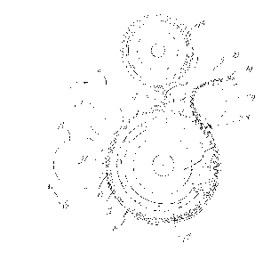
BRIEF DESCRIPTION OF THE DRAWINGS
Fig. 1 is a schematic side elevation view of the
5 single facer incorporating the construction of the presently
preferred embodiment of the present invention.
Fig. 2 is a schematic side elevation view of a single
facer incorporating another embodiment of the invention.
Fig. 3 is a schematic representation of the flute
10 depth of the bonding roll and the medium web also showing the
sup-ply of steam through the steam chamber.
Fig. 4 is a generally schematic side elevation view of
an alternate embodiment of a single facer of the present
lnvent lon .
Fig. 5 is a generally schematic side elevation of a
further embodiment of a single facer of the present invention.
Fig. 6 is a partial bottom plan view taken on line 6-6
of Fig. 5.
FIG. 7 is a schematic side elevation view of a further
and presently preferred embodiment of a single facer of the
present invention.
DETAILED DESCRIPTION OF THE PREFERRED EMBODIMENT
Referring initially to Fig. 1, a single facer 10
embodiment of the present invention operates to form a
corrugated medium web 12 from an incoming medium web 11 and to
join it to a liner web 13 to form a composite single face web
14, which function is generally characteristic of prior art
single facers. In the embodiment shown, the single facer 10
utilizes the invention of my co-pending U.S. patent application
Serial No. 08/621,998, entitled "Single Facer with Small
Intermediate Corrugating Roll", filed on March 26, 1996.
However, it is understood that the subject invention may be
applied as well to more conventional prior art single facers.
The incoming medium web 11 is directed into the
corrugating nip defined by the interengaging flutes of an upper
corrugating roll 15 and an intermediate corrugating roll 16.
The medium web 15 is deformed in the corrugating nip to provide
the characteristic corrugated medium web 12 which is wrapped
around the intermediate corrugating roll 16 and into the nip
CA 02217798 1997-10-30
formed between intermediate corrugating roll 16 and a fluted
bonding roll 17 comprising a key element in the single facer of
the present invention. The bonding roll 17 includes a fluted
outer surface 18 onto which the corrugated medium web 12 is
transferred.
In a manner known in the art, the flute tips of the
corrugated medium web 12 being carried on the fluted surface 18
of the bonding roll 17 are contacted by a glue roll 20 having a
layer of a typical aqueous starch-based adhesive thereon which
10 is transferred to the flute tips to create continuous glue lines
across the flute tips in the machine direction. Just downstream
from the glue roll 20 the liner web 13 is brought tangentially
into contact with the glued flute tips of the corrugated medium
web 12. Upstream of the initial contact point, the liner web 13
15 is preferably wrapped around the circumference of a preheater
roll 21 which heats the web to at least a temperature
sufficiently higher than the gelatinization temperature of the
adhesive (which is about 150~F (66~C)), preferably at least
about 180 - 212 degrees F. (82-100~C). Either or both of the
20 upper and intermediate corrugated rolls 15 and 16 may also be
heated to cause a preheating of the corrugated medium web 12 as
well. The preheater roll 21 is spaced from the fluted outer
surface 18 of the bonding roll 17 by a distance sufficient to
preclude any significant nip pressure on the joined webs 12 and
25 13. As will be appreciated by those in the art, any method of
conventional preheating, whether by a roll, hot air, or other
radiant energy, or other known source, may be employed in
preheating the web, or it may be found that preheating is not
required in particular applications.
It will be further appreciated by those in the art
that the present invention is not limited to conventional
starch-based adhesive. Any adhesive whose performance is
affected by the phenomena of drying or heating could be employed
in variations of the present invention. For example, PVA
35 adhesives could be employed, as could thermosetting resins such
as phenolic resins.
The absence of a pressure roll or any means for
imposing a joining force on the glue lines between the
corrugated medium web and the liner web distinguishes the single
CA 02217798 1997-10-30
facer of the present invention from prior art devices. Recent
studies have suggested that pressure rolls in prior art single
facers tend to squeeze the adhesive glue lines with sufficient
pressure to actually squeeze the water from the starch adhesive.
Without water, this portion of the glue line extending right
along the flute tip cannot gel, much less form a green bond and
cure. This portion is, therefore, completely lost to the
bonding mechanism and only the portions of the glue lines on the
flanks of the flutes as they curve away from the tips are
available to form the actual glue bond. Furthermore, reliance
on the residual heat in the two component webs to gelatinize the
starch adhesive and to create at least initial dehydration to
provide a green bond, is insufficient. As a result, the
initially joined single face web leaving the high pressure nip
of a conventional single facer has inadequate strength to assure
sufficient single face integrity for subsequent downstream
handling.
In accordance with the primary aspect of the present
invention, adequate green bond strength of the adhesive joints
is created on the bonding roll 17 by applying heat to the
freshly joined single face web 14 at a temperature and for a
time sufficient to establish a green bond. Green bond strength
relies on the removal of water from the adhesive, either by
migration into the paper or from evaporative dehydration of the
aqueous starch adhesive. The latter is the more significant
phenomenon, and is also ~men~hle to manipulation, and,
therefore, it is necessary to raise the web temperature
significantly above the initial gelatinization temperature to
achieve an adequate green bond strength. In addition, the web
must be maintained at the higher temperature level for an
adequate length of time. Furthermore, and specifically in
accordance with the present invention, the glued single face web
14 is maintained at a green bond formation temperature and for a
necessary period of time on the bonding roll 17 itself. In this
manner, the integrity of the single face web is retained and
assured by retaining the corrugated medium web on the mating
fluted surface 18 of the bonding roll with the outer liner web
13 in intimate (but low pressure) contact therewith. It will be
appreciated that, in prior art single facers, directing the
CA 02217798 1997-10-30
- 10 -
single face web away from the transfer roll or pressure roll
immediately after nipping contact will preclude the formation of
an adequate green bond to maintain web integrity. Although the
latent heat in the web may be sufficient to eventually form a
green bond, such bond may not occur until the web has been
transferred over reversing takeup rolls and the like and into
the bridge storage, causing undesirable flexing and disruption
of the inadequate bond.
Referring again to Fig. 1, the bonding roll 17 is
preferably heated internally with a conventional live steam
system of a type well known in the art. In such systems, live
steam is supplied to the interior of the roll by an axially
disposed steam supply tube of a type, for example, discussed
with regard to the Fig. 2 embodiment. The bonding roll 17 is
heated to provide a temperature at the fluted outer surface 18
sufficient to raise the temperature of the web and adhesive to
200~F (93~C) or higher, and preferably to about 215~F (102~C),
to facilitate dehydration and formation of the green bond. In
order to achieve sufficient heat transfer to raise the adhesive
temperature to that point, the bonding roll surface temperature
should be at about 360-380~F (182-193~C) or more. Although
green bond formation will begin immediately at the indicated
temperature, substantial dehydration of the glue line and
adjoining web surfaces must occur before adequate green bond
strength is realized. It has been estimated that 80% of the
moisture must be removed for full green bond strength. Thus, in
accordance with the other aspect of the invention, the single
face web 14 is retained on the surface of the bonding roll 17
for a period of time adequate to assure good green bond
formation. Although commentators in the art have suggested that
green bond formation begins as quickly as 20 milliseconds after
component web joinder in the pressure roll nip, it is believed
that retaining residence of the single face web on the fluted
bonding roll for a much longer period of time, up to about 500
milliseconds, will provide the necessary full green bond
strength. In the Fig. 1 embodiment, it will be seen that the
single face web is wrapped substantially more than 180~ around
the circumference of the bonding roll before the tangential
takeoff point 23 where the single face web is back wrapped
CA 02217798 1997-10-30
around a takeoff roll 24. The position of the takeoff roll 24
may be adjusted to vary the amount of wrap on the bonding roll
between the takeoff point 23 and the upstream initial tangent
contact point 22 where the liner web 13 is initially joined with
the corrugated medium web 12. It should be noted that any known
system of takeoff rolls, whether a single or multiple roll
design, can be employed to perform the function of takeoff roll
24, as known in the art.
As indicated above, in order to provide a 500
millisecond residence time of the single face web on the bonding
roll, consideration must be given to the speed of the web
through the single facer, bonding roll diameter, and the amount
of circumferential wrap available. With respect to the latter
consideration, it is obvious that space must be made available
for the intermediate corrugating roll 16, the glue roll 20 and
the preheater roll 21 or other means of bringing the liner web
13 onto the bonding roll. By making the diameter of the bonding
roll substantially larger, more space is made available for the
other components and, simultaneously, the circumference is
enlarged to accommodate a longer single face web wrap thereon.
With a web speed of 1,000 feet per second, a 4 foot diameter
bonding roll 17 will require about 240~ of single face wrap to
provide a web residence time on the roll of 500 milliseconds.
In the embodiment shown, the large diameter bonding roll will
easily accommodate this arrangement.
In the single facer apparatus shown in Fig. 2, a
conventional upper main corrugating roll 25 and a lower bonding
roll 26 are mounted to capture therebetween and operate in
rotating interengagement with a small intermediate corrugating
roll 27. Each of the rolls 25, 26 and 27 is provided with a
conventional fluted peripheral surface, as described with
respect to the Fig. 1 embodiment, but the flutes of bonding roll
26 are of a greater depth, as will be described in detail below.
After the flutes 28 have been formed in the medium web
30 by the corrugating nip between corrugating rolls 25 and 27,
the fluted medium web 31 is held in contact with the outer
circumference of the intermediate corrugating roll 27 by a
conventional vacuum system by which vacuum is applied via
suitable networks of axial and radial vacuum passages 32.
CA 022l7798 l997-lO-30
- 12 -
After being carried around the intermediate
corrugating roll 27, the now corrugated medium web 31 iS
transferred to the bonding roll 26 at the nip therebetween. As
with the intermediate corrugating roll 27, the bonding roll 26
has a vacuum system in which vacuum is applied via suitable net-
works of axial and radial vacuum passages 33 to the corrugated
medium web 31. The supply of vacuum to the corrugated medium
web 31 will be discussed in greater detail below. As the
corrugated medium 31 travels along the outer circumference of
the bonding roll 26, the glue roll 34 of a conventional glue
applicator makes rotating contact with the flutes tips of the
corrugated medium 31 while it is in contact with the bonding
roll.
A liner web 35 iS carried around a portion of a pre-
heater roll 36 where it is brought into contact with the glued
flute tips of the corrugated medium 31 at a tangent contact or
liner infeed 37. In accordance with the invention, the point of
connection 37 between the liner 35 and the corrugated medium 31
does not include any pressure between the corrugated medium 31
and the liner 35. Preferably, the pre-heater roll 36 iS spaced
from the outer circumference of the bonding roll 26 by a
distance at least as great as the combined thickness of the
liner 35 and the corrugated medium 31. As in the prior
embodiment, there is no stress applied to either the liner 35 or
the corrugated medium 31, such that the chance of tearing either
of the two webs is greatly reduced. Equally significant, the
glue line at the flute tips is not squeezed to displace the
moisture from it.
After the liner 35 iS introduced into contact with the
glued flute tips of the corrugated web 31, the composite single
face web 40 continues to travel along the outer circumference of
the bonding roll 26. Positioned to be in communication with the
single face web 40 iS a steam chamber 42. The steam chamber 42
is generally connected to a supply of steam (not shown) through
a steam supply tube 44. Steam is introduced through the supply
tube 44 into the open interior 46 of the steam chamber 42 which
is defined by a pair of end walls 48 and an arcuate outer wall
50. Although the steam chamber 42 iS described as shown in Fig.
CA 02217798 1997-10-30
2, any equivalent structure is contemplated as being within the
scope of the invention.
Turning now to Fig. 3, the interaction between the
steam contained in the open interior 46 of the steam chamber 42
and the single face web 40 is more clearly shown. As can be
seen in this figure, the depth of the individual flutes 52
contained on the bonding roll 26 is greater than the depth of
the flutes 53 formed in the corrugated medium 31. Because the
bonding roll 26 does not participate in forming the flutes in
the medium 31, the flutes 52 do not have to conform to the flute
profile. The difference in the depth of the flutes 53 and the
flutes contained in the corrugated medium 31 creates a vacuum
cross channel 54 therebetween. Each of the vacuum cross
channels 54 runs the entire axial length of the bonding roll 26
and is in communication with the vacuum passage 33 contained
within the interior of the bonding roll 26 through a vacuum
passageway 56. As can be understood by the arrows in Fig. 3,
the vacuum passageways 56 provide both a pressure gradient and
an outlet for the steam introduced in the open interior 46
through the supply tube 44. Thus, the steam penetrates and
passes through the liner 34 and the corrugated medium 30,
heating the glue lines 58, gelatinizing the starch adhesive.
The addition of further heat drives off additional water,
forming the green bond between the corrugated medium 31 and the
liner 35.
Referring again to Fig. 2, it is desired that the pre-
heater roll 36 be spaced from the bonding roll 26 by distance at
least as great as the combined width of the corrugated medium 31
and the liner 35. In the embodiment shown, a potential problem
can arise when a splice arrives either on the medium web 30 or
on the liner 35. In order to run continuously, the single facer
automatically splices a new paper roll onto the running web as
the expiring roll runs out. The spliced material laps over the
old and new portions producing a short length of web having an
additional thickness of paper. In the embodiment shown in Fig.-
2, that effect will be felt since the steam in steam chamber 42
would likely not penetrate the increased thickness of web,
leading to poor bonding in a portion of the web. This problem
can be avoided altogether by spacing the pre-heater roll 36
CA 02217798 1997-10-30
- 14 -
slightly less than three paper thicknesses from the bonding roll
26. In this configuration, when a spliced portion arrives
(either on the corrugated medium web 31 or the liner 35), the
added thickness will result in the pre-heater roll 36 exerting
pressure on, the combined single face web 40, producing a
pressure-cure bond for only the duration of the splice. For
this period, the invention functions in a manner similar to a
conventional single facer, but reverts automatically and without
any adjustment to the function and advantages of the invention
immediately after the splice is passed through the device.
The main corrugating roll 25, the intermediate
corrugating roll 27, and the bonding roll 26 may be heated with
steam, as is known in the art. Alternatively, in the invention
shown, the provision of a separate heating system for the
bonding roll 26 may be omitted due to the steam being applied to
the bonding roll by the steam chamber 42. In an embodiment
without a separate source of steam being applied to the bonding
roll 26, the roll should heat to a satisfactory temperature of
350-380~F (177-193~C) or greater within minutes of operation due
to the steam in the steam chamber 42. Also, the pressure
gradient applied to the web by vacuum means in this embodiment
could also be applied by providing a pressure source outside the
roll; in either event, the pressure above the web is greater
than the pressure within the bonding roll.
It is contemplated that the heating module 60 may
also be heated by hot air instead of steam, utilizing the same
basic arrangement disclosed. In addition, the bonding roll 62
may be provided with an internal vacuum system, similar to that
previously described.
Another embodiment of a low pressure single facer in
accordance with the present invention is shown in Fig. 4. In
this embodiment, the steam chamber 42 of the previously
described embodiment is replaced with a heating module 60 which
includes a flexible heat transfer surface that may be made to
conform to the glued single face web on the bonding roll to
transmit heat thereto with a very low pressure contact. The
heating module 60, for example, may be similar to a heating
module disclosed in my U.S. Patent No. 5,628,865. The module
60 has a generally arcuate shape and includes an enclosing inner
CA 02217798 1997-10-30
wall 61 made of a thin flexible sheet material, such as .018
inch (.46mm) stainless steel sheet. The thin metal sheet 61 is
formed into a semicircular shape conforming generally to the
outside diameter of the single facer bonding roll 62. The
flexible inner wall 61 comprises the radial inner wall of a
heating module chamber 63. The chamber includes an outer wall
64 which is rigid enough to maintain the semicylindrical shape
of the chamber 63, and a pair of enclosing lateral side walls
65. The chamber 63 is heated by a serpentine arrangement of
steam heating tubes which may be conveniently supplied with
steam from a pair of inlets 67, each of which is in
communication with one of the endmost tubes 66 at the opposite
upper ends of the module. A lower central condensate outlet 68
is connected to a central tube at the bottom of the module.
In a manner generally similar to the previously
described embodiments, the medium web is corrugated by passage
through the nip defined by an upper corrugating roll 71 and an
intermediate corrugating roll 72. The corrugated web 70 passes
onto the bonding roll 62 where a suitable adhesive is applied to
the exposed flute tips with an adhesive applicator 73. A liner
web 74 is brought into tangent contact with the flute tips of
the corrugated medium 70 on the bonding roll 62 just upstream of
one end of the heating module 60.
To provide a low pressure heat transfer from the
heating module 60 to the glued single face web 76 on the bonding
roll, the interior of the heating module chamber 63 is filled
with a suitable heat transfer fluid 76. The heat transfer fluid
may comprise a low density liquid, but a gaseous medium is
preferred. Specifically, a gas with a high thermal
conductivity, such as hydrogen, is preferred. The very thin
flexible inner wall 61 of the heating module, backed by the
fluid-filled chamber interior, conforms very closely to the
outer surface of the liner web 74 of the single face material 75
on the bonding roll 62. This intimate low pressure contact
provides good heat transfer to the web to cure the adhesive
without the application of substantial pressure. This
eliminates the problem of noise and web damage typical of
conventional single facers, and allows the single face web to
move through the heating and curing zone provided by the module
CA 02217798 1997-10-30
- 16 -
60 without undue frictional drag. A downstream vacuum drive
belt 77 may be utilized to assist in pulling the web through the
curing zone on the bonding roll 62. Opposite ends of the
heating module 60 may be provided with suitable actuators 78 to
move the module by a small amount to accommodate web thread-up
and to move the flexible inner wall 61 into and out of heat
transfer contact with the single face web.
Referring now to Figs. 5 and 6, another embodiment of
the invention is shown which includes a heating module 80 that
operates in a manner similar to the Fig. 4 embodiment. In this
embodiment, the flexible heat transfer surface which conforms to
the single face web being carried on the bonding roll 62,
comprises a series of parallel flexible bands 81. The bands 81
extend along a portion of the cylindrical outer surface of the
bonding roll 62 on which the single face web 75 is being
carried. The bands 81 may comprise stainless steel strips,
having thickness of .018 inch (.46mm) and a width, for example,
of 3 to 4 inches (7.6 to 10.2cm). Flexible bands 81 are
positioned in parallel spaced relation across the whole width of
the unit and are preferably closely spaced about 1/8 inch or 3mm
apart.
To maintain intimate low pressure contact between the
flexible bands and the single face web and to provide the
transfer of heat thereto for curing, the bands 81 have secured
to their outer faces a series of heating tubes 82 which extend
in parallel spaced relation across the outer surfaces thereof,
in a direction transverse to the direction of movement of the
single face web on the bonding roll 62. The heating tubes 82
are interconnected to form a serpentine path for a suitable
heating fluid, such as steam, in a manner generally similar to
the previously described embodiment. However, each of the
heating tubes is attached directly to the outer surface of the
flexible metal bands 81, as by soldering, to provide a direct
heat transfer thereto. The heating tubes are provided with
radial inner surfaces 83 which are machined or otherwise formed-
to a radius which will cause the flexible bands 81 to conform
intimately to the cylindrical surface of the single face web 75
on the bonding roll 62. Specifically, the formed radius of the
inner surfaces 83 of the heating tubes is equal to the radius
CA 022l7798 l997-lO-30
- 17 -
defined by the outer surfaces of the bands 81 when the bands are
positioned to intimately contact the cylindrical outer surface
of the single face liner web 74 on the bonding roll.
Steam or other suitable heating fluid is supplied to
the heating module 80 in the same manner as with the heating
module 60 of the Fig. 4 embodiment. Thus, steam may be provided
via inlets 84 communicating with the upstream-most and
downstream-most heating tubes 82. A condensate outlet 85 is
provided in the center or lowermost heating tube 82.
Each of the flexible bands 81 is provided with a pair
of loading cylinders 86 operatively connected to the opposite
ends of the band. In this manner, the laterally spaced parallel
bands 81 may be individually adjusted to provide a heat transfer
contact surface which corresponds directly to the width of the
single face web 75 being made. The loading cylinders 86 need
only move the ends of a flexible band 81 by a very small amount
to move the band out of intimate contact with the web on the
bonding roll. As soon as intimate contact between a heated band
81 and the web is lost, the band will become hotter and will
expand to further remove the band from heat transfer contact.
The remainder of the single facer of the embodiment of Figs. 5
and 6 may include elements which are identical to those
described with respect to the Fig. 4 embodiment, and are
similarly numbered. If desired, other sources of heat could be
substituted for the steam system of this embodiment. For
example, the flexible bands could be provided with electrical
heat members, hot air or radiant heat systems, or other heating
methods known to the art.
In the FIG. 7 embodiment, a large diameter bonding
roll 90 may be constructed in a manner similar to bonding rolls
17 and 26 of the previously described embodiments. Thus,
bonding roll 90 is internally heated to provide a temperature at
the fluted outer surface 91 sufficient to facilitate formation
of a green bond. Unlike the previously described embodiments,
however, bonding roll 90 acts directly with a small diameter
corrugating roll 92 to form a corrugating nip 93 into which the
medium web 94 is directly fed.
Instead of capturing the small corrugating roll 92
between two larger fluted rolls (one of which is the bonding
CA 02217798 1997-10-30
- 18 -
roll), the small corrugating roll 92 is provided with a backing
device which provides the nipping force and prevents deflection
of the roll 92 utilizing a system disclosed in my copending
application entitled "Improved Single Facer with Small
Intermediate Corrugating Roll". Furthermore, the FIG. 7
apparatus eliminates completely a conventional pressure roll of
the type typical of prior art single facers in which two
relatively large diameter corrugating rolls are aligned with a
pressure roll such that the axes of all three rolls lie
generally coplanar. Elimination of the conventional pressure
roll, in this embodiment as well as in previously described
embodiments, provides a much larger circumferential portion on
the bonding roll 90 on which to retain the freshly glued single
face web for curing. Further, the embodiment of FIG. 7, in
particular, eliminates completely the large upper corrugating
roll.
The corrugated medium web 95, exiting the corrugating
nip 93, remains on the fluted surface 91 of the bonding roll
where the exposed flute tips are immediately coated with lines
of adhesive by a glue roll 96 in a manner similar to embodiments
previously described. Just downstream of the glue roll 96, a
liner web 97 is brought into contact with the glued medium web
95 on a liner delivery roll 98 around which the liner 97 is
wrapped and brought generally into tangential contact with the
glued flute tips. As in the previously described embodiments,
the liner roll 98 is preferably spaced from the fluted outer
surface 91 of the bonding roll 90 by a distance sufficient to
preclude any significant nip pressure.
The freshly glued single face web 100 is maintained in
contact with the heated bonding roll 90 with a wrap arm device
101 which allows the single face to be adjustably wrapped around
a circumferential portion of the bonding roll of a selected
length or arc. The wrap arm device 100 includes a pair of
radially extending wrap arms 102 rotatably mounted on the axis
of rotation of the bonding roll 90, but adapted to rotate
independently thereof. An idler roll 103 is mounted between the
radially outer ends of the wrap arms 102, extends the full
length of the bonding roll 90 and is positioned to maintain the
single face web 100 in engagement with the fluted outer surface
CA 02217798 1997-10-30
- 19 -
91 of the bonding roll. A wrap arm drive and locating device
104 is utilized to move the idler roll 103 around the outer
surface of the bonding roll 90 to selectively adjust the amount
of circumferential wrap of the single face web on the bonding
roll. As indicated previously, the use of a small diameter
corrugating roll 92, as well as a more compact location of the
glue roll 96 and the liner delivery roll 98 to position them
closer to the small corrugating roll, will provide for as much
as about 270~ of wrap of the single face web around the bonding
roll. From the idler roll 103 on the wrap arm, the single face
web is delivered to a downstream web drive 105 from which it is
carried to further downstream processing or storage, such as a
conventional bridge storage area.
Pressure on the glued flute tips as the single face
web is carried around the bonding roll 90 is provided directly
as a result of the radially inward force generated by liner web
tension. Web tension and, therefore, the radial pressure
generated on the glued flute tips may be readily varied. For
example, the web drive 105 could be operated at a slight
overspeed with respect to the speed of the web on the bonding
roll 90. Preferably, however, web tension is varied by
retarding the liner web delivery roll 98 with the use of a
suitable adjustable breaking device 106. Thus, tension in the
liner wrapped on the bonding roll replaces a conventional
pressure roll in the single facer. Furthermore, a substantial
portion of the circumference of the heated bonding roll may be
utilized to assure an adequate green bond has formed before the
single face web is removed from the bonding roll.