Language selection

Search

Patent 2217906 Summary

Third-party information liability

Some of the information on this Web page has been provided by external sources. The Government of Canada is not responsible for the accuracy, reliability or currency of the information supplied by external sources. Users wishing to rely upon this information should consult directly with the source of the information. Content provided by external sources is not subject to official languages, privacy and accessibility requirements.

Claims and Abstract availability

Any discrepancies in the text and image of the Claims and Abstract are due to differing posting times. Text of the Claims and Abstract are posted:

  • At the time the application is open to public inspection;
  • At the time of issue of the patent (grant).
(12) Patent: (11) CA 2217906
(54) English Title: METHOD FOR THE CONCENTRATION OF LIQUID MIXTURES
(54) French Title: METHODE DE CONCENTRATION DE MELANGES LIQUIDES
Status: Term Expired - Post Grant Beyond Limit
Bibliographic Data
(51) International Patent Classification (IPC):
  • B01D 1/04 (2006.01)
  • B01D 1/14 (2006.01)
  • B01D 1/22 (2006.01)
(72) Inventors :
  • VEZZANI, CORRADO (Italy)
(73) Owners :
  • VOMM CHEMIPHARMA S.R.L.
  • VOMM CHEMIPHARMA S.R.L.
(71) Applicants :
  • VOMM CHEMIPHARMA S.R.L. (Italy)
(74) Agent: OYEN WIGGS GREEN & MUTALA LLP
(74) Associate agent:
(45) Issued: 2006-12-05
(22) Filed Date: 1997-10-09
(41) Open to Public Inspection: 1998-04-10
Examination requested: 2002-08-09
Availability of licence: N/A
Dedicated to the Public: N/A
(25) Language of filing: English

Patent Cooperation Treaty (PCT): No

(30) Application Priority Data:
Application No. Country/Territory Date
MI 96 A 002091 (Italy) 1996-10-10

Abstracts

English Abstract

The present invention relates to a method for the concentration of liquid mixtures, comprising the step of causing a continuous stream of the liquid mixtures to flow in the form of a turbulent thin layer in contact with a heated wall. For that purpose, a continuous stream of liquid mixture is fed into a turbo-concentrator comprising a cylindrical tubular body (1), a heating jacket (4) and a bladed rotor (8) rotatably supported in the cylindrical tubular body (1). The liquid mixture is centrifuged to form a dynamic and tubular thin layer, the thin layer advancing inside the cylindrical tubular body (1) then being discharged continuously in the form of a stream of concentrated liquid mixture.


French Abstract

La présente invention concerne une méthode de concentration des mélanges liquides, comprenant l'étape de provocation d'un débit continu des mélanges de liquides s'écoulant sous forme d'une couche fine turbulente en contact avec une paroi chauffée. A cet effet, un débit continu de mélange de liquides est alimenté dans un turbo-concentrateur comprenant un corps tubulaire cylindrique (1), une jaquette chauffante (4) et un rotor à lames (8) soutenu de manière rotative dans le corps tubulaire cylindrique. Le mélange liquide est centrifugé pour former une couche dynamique et tubulaire fine, la couche fine s'avançant à l'intérieur du corps tubulaire cylindrique (1) puis étant déchargée continuellement sous forme d'un débit de mélange de liquide concentré.

Claims

Note: Claims are shown in the official language in which they were submitted.

10
CLAIMS
WHAT IS CLAIMED IS:
1. Method for concentration of liquid
mixtures, comprising the steps of:
feeding a continuous stream of a liquid
mixture into a turbo-concentrator comprising
a cylindrical tubular body which has a hori-
zontal axis and which is equipped with an
opening for the introduction of the liquid
mixture and with an opening for the discharge
of the final product, a heating jacket for
heating the internal wall of the tubular body
to a predetermined temperature, and a bladed
rotor rotatably supported in the cylindrical
tubular body where it is rotated at cir-
cumferential speeds variable from 30 to 50
m/s,
centrifuging the liquid mixture to form
a dynamic and tubular thin layer in which the
liquid mixture is maintained in a state of

11
high turbulence by blades of the bladed
rotor,
advancing the dynamic tubular thin layer
to the discharge opening of the turbo-concen-
trator, causing it to flow substantially in
contact with the heated wall of the latter to
the discharge opening,
discharging continuously a stream of
concentrated liquid mixture.
2. A method according to claim 1, wherein a
stream of hot dry air is fed into the turbo-
concentrator in the same direction as the continu-
ous stream of liquid mixture.
3. A method according to any one of claims
1 and 2, wherein a portion of the continuous
stream of concentrated liquid mixture leaving the
turbo-concentrator is fed in again continuously
upstream of the turbo-concentrator.

Description

Note: Descriptions are shown in the official language in which they were submitted.


CA 02217906 1997-10-09
1
METHOD FOR THE CONCENTRATION OF LIQUID MIXTURES
DESCRIPTION
The present invention relates, in its more general
aspect, to the concentration of substantially liquid
mixtures and solutions.
More especially, the invention relates to a method
for the industrial concentration of substantially
liquid mixtures and solutions within all industrial
sectors, such as, for example, the food sector, and
in the disposal of urban refuse, in purification
plants, and in the recovery of heavy metals
contained in aqueous solutions, etc..
Purely for the sake of simplicity, these
substantially liquid mixtures and solutions will be
referred to in the course of the description as
liquid mixtures.
The apparatuses chiefly used for the concentration
of liquid mixtures include multiple-effect
concentrators and vacuum concentrators.
The first type of technology comprises a series
arrangement of two or more concentrators each
comprising a container filled with the mixture to be

CA 02217906 1997-10-09
2
concentrated, a coil heating device which is
immersed in the liquid mixture and which is
generally fed with steam, and finally a pipe system
which connects in series the two or more containers
constituting the plant. The liquid mixture in the
first container is heated and concentrated by means
of mains steam. After having reached a specific
degree of concentration, the liquid mixture is
conveyed into the next container where it is
subjected to an analogous treatment, the only
difference being that, in this case, the mains steam
is replaced by the vapour coming from the first
container, or that released from the liquid mixture
in the first concentration stage. The process just
described can be repeated several times until the
desired concentration is obtained.
With this type of technology, however, it is
possible to reach only a specific degree of
concentration, which is determined by the viscosity
of the product to be treated, because it is
necessary to ensure that the product, which becomes
gradually more dense, runs well from one container
to another in the concentration plant in order to
avoid undesired obstructions in the connecting pipe
system. This problem is further aggravated if the
liquid mixture to be treated contains various types
of fibre, or aggregates of insoluble salts or the

CA 02217906 1997-10-09
3
like. A further disadvantage presented by any type
of liquid mixture to be treated, however, is that of
the encrustations which form on the heating coils
which have to be dismounted and cleaned
periodically.
The second type of apparatus, the vacuum
concentrators, normally comprise a container heated
by a jacket or a heating coil, the latter being
immersed in the liquid mixture to be treated, and a
condenser for condensing the vapour formed in the
concentration stage.
This type of apparatus, however, has the
disadvantage of operating batchwise which, as is
well known, limits productivity and requires more
complex management operations . Added to this are the
above-mentioned problems of the encrustations on the
coils or other parts of the plant, and also a
considerable waste of energy owing to the
maintenance of reduced pressure in the plant.
The problem underlying the invention is to provide
a method for the concentration of liquid mixtures of
various kinds which avoids all the above-mentioned
disadvantages.

CA 02217906 1997-10-09
4
The problem is solved, in accordance with the
invention, by a method for the concentration of
liquid mixtures, comprising the stage of causing a
continuous stream of the liquid mixtures to flow in
the form of a dynamic turbulent thin layer in
contact with a heated wall.
The use of dynamic turbulent thin layers in contact
with a heated wall has been found to be especially
advantageous because it involves the formation of a
large exchange surface, which substantially
accelerates the processes of transporting mass and
energy. Therefore, the use of thin layers enables
the dimensions of the entire plant to be
substantially reduced and the energy costs to be
considerably decreased.
In a preferred embodiment of the present invention,
a turbo-concentrator is used as the concentration
unit. Of the machines of this type, that produced
and marketed by the company VOMM-IMPIANTI E PROCESSI
of Milan (Italy) has been found to be especially
useful and advantageous. This machine basically
comprises a cylindrical tubular body, having a
horizontal axis and closed at the opposite ends,
which is provided with openings for the introduction
of a liquid mixture to be treated and a stream of
dry air travelling in the same direction, a heating

CA 02217906 1997-10-09
5
jacket for heating the internal wall of the tubular
body to a predetermined temperature, and a bladed
rotor rotatably supported in the cylindrical tubular
body where it is rotated at a circumferential speed
variable from 30 to 50 m/s.
With the use of a turbo-concentrator of the above-
mentioned type, the method of the invention is
characterised in that it comprises the stages of:
- feeding a continuous stream of liquid mixture
into the turbo-concentrator in which the bladed
rotor is rotated at circumferential speeds variable
from 30 to 50 m/s,
- centrifuging the liquid mixture to form a dynamic
and tubular thin layer in which the liquid mixture
is maintained in a state of high turbulence by the
blades of the bladed rotor,
- advancing the dynamic and tubular thin layer to
the discharge opening of the turbo-concentrator,
causing it to flow substantially in contact with the
heated wall of the latter to the discharge opening,
- discharging continuously a stream of concentrated
liquid mixture.
The use of the method just described, because it is
continuous, permits much higher productivity than do
the batch or semi-batch techniques of the prior art .
The use of an apparatus like that described above

CA 02217906 1997-10-09
6
also substantially reduces the problems associated
with the maintenance and the cleaning of the plant
and thus the general management and production
costs.
Advantageously, a stream of hot dry air is fed into
the turbo-concentrator in the same direction as the
stream of liquid mixture; thus, the speed at which
vapour is removed is increased, which further
reduces the residence times necessary for the stream
in the concentration unit.
The above-mentioned stream of dry air preferably has
a flow rate which may be up to 6 Nm3 of air per litre
of evaporated water.
A further embodiment of the invention provides,
where appropriate, for the recycling of a portion of
the discharged concentrated stream upstream of the
turbo-concentrator; this increases the viscosity of
the incoming stream, which facilitates the operation
of the concentrator.
The characteristics and advantages of the invention
will become clear from the following description of
embodiments of the method described above which is
given with reference to an apparatus shown

CA 02217906 1997-10-09
7
diagrammatically in the single appended drawing,
which is provided purely by way of illustration.
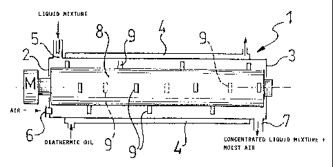
Referring to the above-mentioned drawing,, an
apparatus used for the method of concentration
according to the invention comprises a turbo-
concentrator formed basically by a cylindrical
tubular body 1 which is closed at the opposite ends
by bases 2, 3 and which is provided coaxially with
a heating jacket 4 through which a fluid, for
example diathermic oil, is to flow in order to
maintain the internal wall of the body 1 at a
predetermined temperature.
The tubular body 1 is provided with an opening S for
the entry of the liquid mixture to be concentrated,
an opening 6 for the stream of hot dry air, and also
an opening 7 for the discharge of the concentrated
liquid mixture.
A bladed rotor 8, the blades 9 of which are arranged
helically and are orientated to centrifuge and
simultaneously convey to the outlet the liquid
mixture to be concentrated, is rotatably supported
in the tubular body 1.
A motor M is provided to operate the bladed rotor at
variable speeds.

CA 02217906 1997-10-09
8
EXAMPLE 1
A 35o solution of acetylated starch in acetic acid
having a degree of acetylation equal to saturation
was fed continuously into the turbo-concentrator
described above at a flow rate of 100 kg/h. The
internal wall of the turbo-concentrator was
maintained at a temperature of 130°C. The bladed
rotor, rotating at a circumferential speed of 40
m/s, centrifuged the liquid mixture against the wall
of the turbo-concentrator where it formed a dynamic
and turbulent tubular thin layer. After a residence
time of 30 seconds, the stream of solution leaving
the turbo-concentrator 1 was conveyed into a
suitable storage unit (not shown). The solution so
obtained had a concentration of 800.
EXAMPLE 2
A solution of polypropylene carbonate in methylene
chloride, having a solids content of 20%, was fed
continuously at a flow rate of 100 kg/h into the
turbo-concentrator described above, in the same
direction as a stream of hot dry air having a flow
rate of 500 m3/h. The temperature of the internal
wall of the turbo-concentrator was 120°C, the
circumferential speed of the bladed rotor was 40 m/s
and the residence time in the turbo-concentrator was

CA 02217906 1997-10-09
9
1 minute. The stream leaving the turbo-concentrator,
having a 90% solids content, was then discharged in
the form of a molten mass and conveyed to a suitable
storage unit.
EXAMPLE 3
A 75% solution of sorbitol in water was fed into the
turbo-concentrator at a flow rate of 100 kg/h. The
temperature of the internal wall of the turbo-
concentrator 1 was 140°C, the circumferential speed
of the bladed rotor was 40 m/s, while the residence
time in the turbo-concentrator 1 was 2 minutes. The
concentrated stream leaving the turbo-concentrator
exhibited a 99% solids content.
EXAMPLE 4
A saline solution of dump effluent as such or coming
from a membrane concentration plant with an average
solids content of 2% was fed into the turbo-
concentrator at a flow rate of 1000 kg/h. The
temperature of the internal wall of the turbo-
concentrator 1 was 240°C, the circumferential speed
of the bladed rotor was 40 m/s, while the residence
time in the turbo-concentrator 1 was 2 minutes. The
concentrated stream leaving the turbo-concentrator
exhibited a 50o solids content.

Representative Drawing
A single figure which represents the drawing illustrating the invention.
Administrative Status

2024-08-01:As part of the Next Generation Patents (NGP) transition, the Canadian Patents Database (CPD) now contains a more detailed Event History, which replicates the Event Log of our new back-office solution.

Please note that "Inactive:" events refers to events no longer in use in our new back-office solution.

For a clearer understanding of the status of the application/patent presented on this page, the site Disclaimer , as well as the definitions for Patent , Event History , Maintenance Fee  and Payment History  should be consulted.

Event History

Description Date
Inactive: Expired (new Act pat) 2017-10-09
Letter Sent 2007-02-27
Inactive: Payment - Insufficient fee 2007-02-27
Inactive: Entity size changed 2007-02-06
Inactive: Office letter 2007-02-06
Inactive: Corrective payment - s.78.6 Act 2006-12-22
Final Fee Paid and Application Reinstated 2006-12-22
Reinstatement Request Received 2006-12-22
Grant by Issuance 2006-12-05
Inactive: Cover page published 2006-12-04
Deemed Abandoned - Failure to Respond to Maintenance Fee Notice 2006-10-10
Inactive: Final fee received 2006-08-02
Pre-grant 2006-08-02
Inactive: IPC from MCD 2006-03-12
Notice of Allowance is Issued 2006-02-10
Letter Sent 2006-02-10
Notice of Allowance is Issued 2006-02-10
Inactive: Approved for allowance (AFA) 2005-11-01
Amendment Received - Voluntary Amendment 2005-10-05
Inactive: S.30(2) Rules - Examiner requisition 2005-06-20
Letter Sent 2002-09-26
Request for Examination Received 2002-08-09
Amendment Received - Voluntary Amendment 2002-08-09
Request for Examination Requirements Determined Compliant 2002-08-09
All Requirements for Examination Determined Compliant 2002-08-09
Application Published (Open to Public Inspection) 1998-04-10
Classification Modified 1998-01-29
Inactive: IPC assigned 1998-01-29
Inactive: First IPC assigned 1998-01-29
Inactive: IPC assigned 1998-01-29
Inactive: Courtesy letter - Evidence 1997-12-23
Filing Requirements Determined Compliant 1997-12-18
Inactive: Filing certificate - No RFE (English) 1997-12-18
Application Received - Regular National 1997-12-17
Inactive: Single transfer 1997-12-12

Abandonment History

Abandonment Date Reason Reinstatement Date
2006-12-22
2006-10-10

Maintenance Fee

The last payment was received on 2006-09-22

Note : If the full payment has not been received on or before the date indicated, a further fee may be required which may be one of the following

  • the reinstatement fee;
  • the late payment fee; or
  • additional fee to reverse deemed expiry.

Please refer to the CIPO Patent Fees web page to see all current fee amounts.

Owners on Record

Note: Records showing the ownership history in alphabetical order.

Current Owners on Record
VOMM CHEMIPHARMA S.R.L.
Past Owners on Record
CORRADO VEZZANI
Past Owners that do not appear in the "Owners on Record" listing will appear in other documentation within the application.
Documents

To view selected files, please enter reCAPTCHA code :


To view images, click a link in the Document Description column. To download the documents, select one or more checkboxes in the first column and then click the "Download Selected in PDF format (Zip Archive)" or the "Download Selected as Single PDF" button.

List of published and non-published patent-specific documents on the CPD .

If you have any difficulty accessing content, you can call the Client Service Centre at 1-866-997-1936 or send them an e-mail at CIPO Client Service Centre.


Document
Description 
Date
(yyyy-mm-dd) 
Number of pages   Size of Image (KB) 
Representative drawing 1998-04-27 1 9
Abstract 1997-10-09 1 20
Description 1997-10-09 9 262
Drawings 1997-10-09 1 15
Claims 1997-10-09 2 45
Cover Page 1998-04-27 1 49
Claims 2005-10-05 2 41
Representative drawing 2006-11-07 1 11
Cover Page 2006-11-07 1 39
Filing Certificate (English) 1997-12-18 1 164
Courtesy - Certificate of registration (related document(s)) 1998-04-23 1 117
Reminder of maintenance fee due 1999-06-10 1 112
Reminder - Request for Examination 2002-06-11 1 118
Acknowledgement of Request for Examination 2002-09-26 1 177
Commissioner's Notice - Application Found Allowable 2006-02-10 1 162
Courtesy - Abandonment Letter (Maintenance Fee) 2007-02-19 1 175
Notice of Reinstatement 2007-02-27 1 165
Correspondence 1997-12-23 1 32
Correspondence 2006-08-02 1 32
Fees 2006-12-22 2 85
Correspondence 2007-02-06 1 31