Note: Descriptions are shown in the official language in which they were submitted.
CA 02217962 1997-10-09
' 1 ; . " , . .
;.", , ~ ;.:~ .. ' ~ e,
' ~ ~ "., ~ ~ ":
.. . ..
1 DES CRIPTION
2 MULTIFUNCTION CONTAINER. PARTICULARLY FOR SKI
3 BOOTS. ICE SKATES OR ROLLER SKATES OF THE SINGLE
4 WHEEL TYPE
Technical Field
6 This model has for object a multifunction container,
7 particularly for ski boots.
8 The innovation finds particular even if not exclusive
9 application among the accessories and the promotional articles,
in general destined to the sector of sports shoes.
11 Background Art
12 In prior art, ski boots, ice skates and roller skates are
13 known.
1~. These are essentially characterised by a structure
1~ somewhat heavy and undoubtedly of a certain dimension, which
16 is the source of various problems.
17 Firstly the transport, from and for the place destined for
18 the exercise of the sporting activity.
19 A first category, the users provided with cars certainly
feel the objective discomfort less, however, they are mostly
21 obliged to pick up the boots from the basement, and introduce
22 them, as they are and higgledy piggledy,' in the boot of the car.
23 Having arrived at the destination, they have to take the
24 shoes and put them on which in the meantime, not being heated
by the internal heating of the cabin, they will also have reached
26 a temperature close to that of the environment.
27 First drawbacks, therefore, can be verified in the sudden
28 displacements of the shoes, which being rigid, besides causing
AMEtdDED SHEET
CA 02217962 1997-10-09
,; ~ ; , . . :. , ',
~% ..
'~~~ .. ;
1 noise during the drive and therefore distraction of the driver,
2 can be the cause of slight damages to the internal parts of the
3 boot or at least to the other objects contained therein.
4 Secondly, the necessity of being able to arrange the shoe
inside the boot at least at a lukewarm temperature is known to all.
6 In order to facilitate the fitting and shaping of the shoe, an
7 operation that should be carried out removing the shoe and
8 introducing it in the cabin of the car, separated by the hull.
9 However because of the discomfort and complexity of the
-operation, as both the extraction and the reintroduction is
11 difficult, the majority of people do not do it, adapting themselves
12 instead to wearing the shoes as they are.
13 Regarding the phase following the use, the main drawback
14 instead, is dictated by the fact that the boots are introduced in the
boot of the car, dirty and full of snow, notwithstanding that they
16 may also be shaken to remove the more consistent parts.
17 Drenching the support surface, one will therefore have
18 persistent humidity on the inside of the ski boot with emission of
19 bad odours, but also in the boot of the car, besides wetting the
surrounding objects.
21 A solution has been proposed by the use of well known
22 technical bags supplied with the ski boots or placed on the
23 market as promotional articles.
24 These are made up of a soft container, obtained by means
of the sewing of a fabric or cloth externally elasticised, provided
26 on the upper part with two robust grip handles, and of a zip,
27 generally placed in the centre, that allows the total opening of
28 the bag.
AiVIEidDED SHEET
CA 02217962 1997-10-09
. 3 ~_ ~ , - . ..
' ~ ~ >
' ': ' ' ,
..' . ..
"'
1 The necessity of using the bag, is dictated above all in
2 those transfers carried out by the use -of public transport means,
3 e.g. bus type, where the boots, separated by the other luggage
4 find place amassed in common.
A first drawback is noticeable because of this specific
6 position, as the stacking of more bags together with thejerks of
7 the bus can cause breakage, at times irreparable at least of the
8 cloth of the bags. Secondly, at the end of the use, the boots placed
9 in the bag, impregnate at least internally the fabric,
contributing to the formation of humidity that persists also
11 inside the boots.
12 Finally, the traditional type bag, due to the material used,
13 is subjected to netting dirty somewhat frequently, not being able
14 to clean it with ease.
1 ~ Regarding the position, always of the boots, during the
16 period of non-use, not only seasonal, one prefers as a rule the
17 tidy arrangement on common shelves or other shelves in
18 general found in the basement of the house.-
19 This does not allow, notwithstanding the attention of the
personnel, to prevent the shoes from getting dusty. Unavoidably
21 during the period of non-use dust will form, not only on the
22 outside but also and above all on the inside.
23 An alternative can consist in providing a suitable cloth or
2~- sheet, to arrange wholly for example by wrapping the row of
boots of an average family.
26 A second and more effective alternative consists in
27 rearranging the boots on the inside of the original packaging
28 purchased.
AMENDED S~1EE~'
CA 02217962 1997-10-09
q, . ; . , " , ..
' ~ ;: . ;
,~" , ~ ..., , ..:
,
',.
..
1 This regards in more detail cardboard boxes of great
2 thickness, obtained by convenient blanks, which realize two
3 half-hulls hinged on one side, on the other side providing tabs to
4 allow the Locking of same.
S Along one side of the structure, a handle in plastic
6 material and retractable is additionally provided, which
7 facilitates the transport.
8 The drawbacks of this solution consist essentially in the
9 excessive dimension of the cardboard boxes, as they are
structured to accommodate the couple of boots in a position
11 distended and opposite according to the more traditional scheme.
12 Secondly, the material with which they are obtained, does
13 not allow the ordinary transport of shoes, neither the
14 introduction of these wet or even only damp, requiring the boots
therefore to be perfectly dried.
16 The same drawbacks can be verified also in other sporting
17 activities, such as those in which one on the inside an internal
18 shoe is provided.
19 This is case for example of single blade roller skates or ice
skates, e.g. ice hockey, artistic skating, and other activities,
21 where it is common to carry with one one's own equipment.
22 In both the cases, the drawbacks, if compared to the
23 transport solutions of the ski boot, are greater, as, when carried
24 in a bag of the traditional type, or even not rigid, the shoes
because of their substructure will persist on the bottom of the
26 bag in an un-uniform way> stressing only a minimum part of the
27 base of the bag.
28 This naturally causes an incorrect distribution of the load,
- ~,MFraoED st~F~r
' CA 02217962 1997-10-09
. 5 , , ,., , , ,
, ;: .
-,~. , . , 1,., , ...
1
" 1 " 1
1 which above free to move, on the inside of the bag.
all is
2 In addition to the drawbacks already detected, a recurrent
3 wear in the
parts more
stressed will
result, and
because of
4 irregular tensiona frequent breakage results even of the
handles.
6 CH-A-547 066 discloses a multifunction container
7 comprising a rigid, aerated and obtained in plastic material,
hull,
8 a closable accessshutter hinged to said hull and provided with,
9 locking means
and having
a handle.
This container realized as a parallelepiped case opening Like
is a
11 suitcase and able to contain a pair of boots, placed on the
being
12 same plane, opposite the other, divided by a diagonal
one
13 diaphragm, to id position difficulty.
avo
14 This solution however bulky and not practical because the
is
boots:
16 - are --difficultinsert and remove, because of the opposite
to
17 placement;
18 - must be placed or removed from above increasing
the
19 difficulty.
The aim of this invention is that to
avoid the above-
21 mentioned drawbacks.
22 This and other aims are reached with this invention
23 according to the characteristics as
in included claims solving the
24 arising problems by a multifunction particularly
container, for
ski boots, ice skates and single blade
roller skates of the ~ type in
26 which a hull, rigid and aerated, is plastic material,
obtained in
27 provided with an opening, closable withat least
one
28 corresponding access shutter, said accessbeing hinged
shutter to
AMFMD~D S~-IE~'
~1 CA 02217962 1997-10-09
,
' = ;~ , ; ;
, ~ ..~, , ~ , ".,
""' ., ...
, ,' . ..'
1 said hull, access shutter being closable r part by
said on the uppe
2 locking means;and in which said hull is providedexternally
3 with a handlecharacterised in that:
4 - the shape said hull, in side view, resembleshaving in
of a boot
front the of the tip of a shoe and able a closed
shape to receive
6 pair of boots
in upright
position;
7 - said openingis placed at the back, opposite tip shape,
to said
8 said opening
being hinged
in opposition
sideways
for rotation
9 from a closure position to an opening position,tipping
backwards;
11 - said opening extending the respective closure upwards by bent
12 end
13 - said bent end terminating with a fastening tongue, cooperating
1 ~. with a top release button on the upper part of the hull.
1 ~ In this way, besides solving the drawbacks raised in the
16 preceding solutions, it is possible to obtain a container
17 particularly useful, as:
18 - the boots can be easily inserted and removed in pair in the
19 exact upright position, and dirt from the bottom of the boots
remains on the bottom of the container, where a hollow is
21 provided.
22 - it allows an easier transport, being able to be placed tidily on
23 the inside of the boot of the car, eventually also with
24 modularization function being able to be hooked to a similar
container;
26 - it avoids the dispersion in the environment of humidity and
27 does not impregnate the interior surfaces of the car with water ;
28 - the insulating material with which it may be obtained, allows
A~IE~IDED St-!~F~
CA 02217962 2000-02-25
1 7
2 the maintenance of the shoes at an acceptable temperature for fitting;
3 - the particular sturdiness, that derives from the rigidity of the
structure,
4 facilitates the transport also in conditions not particularly easy, as the
higgledy
piggledy position in common housings;
6 - it allows finally a rational positioning, protected from dust and humidity
7 during the periods of non-use, lending itself to the eventuality of
immediate
8 use.
9 In a broad aspect, then, the present invention relates to a multifunction
container, comprising: a rigid hull made of a plastic material, said hull
having
11 an opening therein, an upper part, a front, a back, a base, a top release
button
12 on the upper part, and a shape which in side view resembles a boot,
including
13 the front having the shape of the tip of a shoe, said opening being located
at
14 the back of said hull opposite to said shape of the tip of a shoe, and said
hull
being able to receive a pair of boots in an upright position; an external
handle
16 on said hull; an access shutter hinged on said hull so as to be capable of
tilting
17 backwards from a position closing said opening to a position exposing said
18 opening, said access shutter comprising an upper bent end terminating in a
19 fastening tongue that is cooperable with said top release button; a clog on
said
base of said hull for engaging the ground, said clog comprising small holes
21 and forming a space internal to said container; and an expanded flexible
plastic
22 material located in said hull at a position corresponding to said clog and
23 separated from remaining internal space in said hull by an extractable grid
24 fixed internally of said hull.
CA 02217962 2000-02-25
1 7~a~
2 In another broad aspect, the present invention relates to a multifunction
3 container, comprising: a rigid hull made of a plastic material comprising an
4 upper part, a front, a back, a base, sides extending from said front to said
back
and upward from said base to said upper part, and a shape which in side view
6 resembles a boot, including the front having the shape of the tip of a shoe
with
7 the shoe pointing in a forward direction away from said back of said hull,
said
8 hull having an opening located at said back of said hull opposite to said
shape
9 of the tip of a shoe and rearward of said sides, and said hull being able to
receive a pair of boots in an upright position; an external handle on said
hull;
11 and an access shutter hinged on said hull at said back of said hull and on
said
12 sides of said hull on opposite sides of said opening so as to be capable of
13 tilting rearwards from a position closing said opening to a position
exposing
14 said opening.
These and other advantages will be shown in the following specific
16 description of a preferred solution with the help of the included drawings,
17 whose details should not be intended as imitative but preferably
illustrative.
18 Figure 1 is a partial view of the container, represented in a schematic
19 and sideways manner with a partially opened access shutter highlighted on
the
back side.
21 Figure 2 represents a A-A sectional view of the hinge of the access
22 shutter referring to the previous figure.
CA 02217962 2000-02-25
1 7(b)
2 Figure 3 represents a schematic view of an ideal shape of the container
3 where the internal part forming the bottom of same and the support of the
4 shoes with flat bottom is highlighted.
Figure 4 is a partial view of a reticle or grid applied on the bottom of
6 the container.
7 Figure 5 is a partial view of the upper part of the boots container, in
8 which a locking system of the access shutter is shown.
9 Figure 6 is a partial view of an eventual second shutter hinged on the
front part of the same container.
CA 02217962 1997-10-09
- _ _ , . .. ,._., .
_ ; . ,
;.; ,
,~ ~ ; ; :,., , ..:
~ ..
. . .. .
1 Finally, Figure 7 shows an encaseable handle for the
2 lifting and the transporting of the container.
3 Figure 8 shows a schematic transparent view of the container
4 having a roller skate inside.
S Figure 9 shows a back view of the container with its back access
6 shutter opened (not shown ), having a pair of roller skates inside
7 and wherein the respective rollers are encased in the thickness
8 of the shaped base of the container.
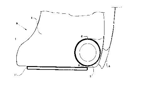
9 Referring to the Figures, one can see an aerated container
(A), preferably obtained in rigid plastic material, in a possible
1 1 solution also insulated, is made up essentially of a hull ( 1) having
12 a rather rounded shape that, seen from the side, resembles in a
13 certain way the shape of a shoe.
1=1 The base of said hull (1) is provided with a clog (1') for
1 ~ placing on the ground, eventually provided with small holes,
16 letting the ends protrude, heel and prod, over the same.
17 Purpose of said clog (1'), is substantially to obtain an
18 interspace, internally to said container, where a sponge can be
19 housed (2) held on the bottom of the container by a removable
reticle or grid (3), also in plastic material.
21 The grid (3) is flexible able to be easily introduced and to
22 adapt the shape of the bottom of the boots. After insertion the
23 grid can be encased beneath an encasing internal rim ( 1 ") ,
24 obtained in a discontinuous way on the internal perimeter of the
hull (1).
26 For allowing the introduction on the inside of the
27 container (1), of at least one pair of ski boots, roller skates or ice
28 skates, a back access shutter (4) is provided, which is
A~IEIdDED S#~FFj
CA 02217962 1997-10-09
9 . , .; . . , ,
"
~ , ~~- , ; , ..:, , ,.
~;., ~ . . ,
1 downwardly hinged on both sides of said hull.
2 In this solution, on the sides of the hull (1) and in logic
3 correspondence, suitable slots are provided on the inside of
4 which are housed the opposed side shutter hinges (5) that allow
the opening of the shutter (4). The shape of the access shutter
6 (4), extends over both the back of the container (1 Fig. l) and its
7 upper part (Ref.4-4' Fig.S) of the container, obtaining a turned-
8 up surface (4') almost orthogonal to the back on the upper part
9 following the shape of the container (A-1).
The upper end of the access shutter (4-4') is equipped,
11 centrally, with a tongue (6) on the same plane, provided with a
12 lock tooth (6') to lock on the inside of a corresponding
13 engagement means (7), made up essentially of a harpoon
14 disengageable by the action of the fingers.
1 ~ Always on the upper part of the container hull, in position
16 next to the lock (7), or almost straddling s-ame, a handle (8) is also
17 provided, of the encaseable type (8'-9 Fig.7).
18 The handle of the disappearing type (8), is obtained by
19 encased shape (8'-9 Fig.7) in the upper part of the hull (1), said
encasing shape is a hollow that resembles the shape of the same
21 handle so that this, in a lowered position, does not offer
22 protrusive surfaces. In order to facilitate the grip, and in
23 proximity of the cross of the handle (8), on the hull (1) a niche
24 (9) may be provided, so as to allow ,the introduction of the
fingers.
26 Finally, in a preferred solution, a second shutter (10) may
27 be provided on the opposed side e.g. in the front and upper part
28 of the container (e.g. position of the instep of the foot), for
a~Fra~Ea s.~EFr
CA 02217962 1997-10-09'
1p ~ . - .
;,' ~ ''~ ,
." " : . , ~ : ,,
- , , , ~~ ,.. ,
". , ~.
.. .
1 communication with the inside of said container (1), for example
2 to introduce in it the gloves.
3 The hinging of this second access shutter ( 10) is provided
4 downwardly, with respective lock, while the upper part of the
second access shutter provides a grip (11) for closing it. A hole
6 ( I 2) is provided in the locking position ( 1 1 ) allowing
7 transpiration and insertion of the finger to allow opening of the
8 second shutter.
9 Figure 6 shows only one part of the front shape of the
container ( 1 ) with its respective second shutter ( L 0), the left side
I1 being cut away. The cutting being indicated by a tortuous bold
12 broken line.
13 Similarly, the first access shutter (~.'-~.) extends backwards
1:I downwardly, being interrupted by a similar tortuous bold broken
1 ~ line Fig., and Likewise for the hull of the container. In other
16 words Fig. completes the missing upper part of Fi~~ 1, even if one
17 is represented in a perspective way and the other sideways.
18 For Ice skates or for single blade roller skates (13-13'), the
19 shape of the container hull (1) can remain the same (B) as the
first one (A). Similarly the shutters.
21 The bottom ( 14) of the container provides on the inside a
22 removable layer (15), which may be of absorbent and soft
23 material such as sponge, or of semirigid material, provided that
24 in both cases longitudinal slot seats (16, 16') are allowed or
provided.
26 Said slot seats (16, 16'), the bottom (16") of which remains
27 away from the bottom (1~) of the container (A/B-1), have a size,
28 respectively in length and in height, calculated, on the base of
AMEtdDED SHEET
CA 02217962 1997-10-09
1 1 ~ ; , : ~ ~ . .,
...,
~ ~ ° w v W
1 the average space occupied by the wheels or blade ( 13').
2 Finally, in an alternative solution to the preceding one,
3 this slot seat layer (15) can be obtained integrated in the hull (1),
4 not interfering in any way with the lodging of previous ski
boots.
AMENDED S~iEFf