Language selection

Search

Patent 2218141 Summary

Third-party information liability

Some of the information on this Web page has been provided by external sources. The Government of Canada is not responsible for the accuracy, reliability or currency of the information supplied by external sources. Users wishing to rely upon this information should consult directly with the source of the information. Content provided by external sources is not subject to official languages, privacy and accessibility requirements.

Claims and Abstract availability

Any discrepancies in the text and image of the Claims and Abstract are due to differing posting times. Text of the Claims and Abstract are posted:

  • At the time the application is open to public inspection;
  • At the time of issue of the patent (grant).
(12) Patent Application: (11) CA 2218141
(54) English Title: PERCUSSION DRILL BIT, AN INSERT, A USE AND A METHOD OF MAINTAINING THE DRILL BIT DIAMETER
(54) French Title: MARTEAU PERFORATEUR A PERCUSSION, PIECE RAPPORTEE, SON UTILISATION ET PROCEDE DE MAINTIEN DU DIAMETRE DU TREPAN
Status: Deemed Abandoned and Beyond the Period of Reinstatement - Pending Response to Notice of Disregarded Communication
Bibliographic Data
(51) International Patent Classification (IPC):
  • E21B 10/56 (2006.01)
  • E21B 10/46 (2006.01)
(72) Inventors :
  • HEDLUND, JAN-GUNNAR (United States of America)
  • ASBERG, BENGT (United States of America)
(73) Owners :
  • SANDVIK INTELLECTUAL PROPERTY AB
(71) Applicants :
  • SANDVIK INTELLECTUAL PROPERTY AB (Sweden)
(74) Agent: GOWLING WLG (CANADA) LLP
(74) Associate agent:
(45) Issued:
(86) PCT Filing Date: 1996-05-14
(87) Open to Public Inspection: 1996-11-28
Examination requested: 2003-05-07
Availability of licence: N/A
Dedicated to the Public: N/A
(25) Language of filing: English

Patent Cooperation Treaty (PCT): Yes
(86) PCT Filing Number: PCT/SE1996/000622
(87) International Publication Number: SE1996000622
(85) National Entry: 1997-10-14

(30) Application Priority Data:
Application No. Country/Territory Date
08/452,136 (United States of America) 1995-05-26

Abstracts

English Abstract

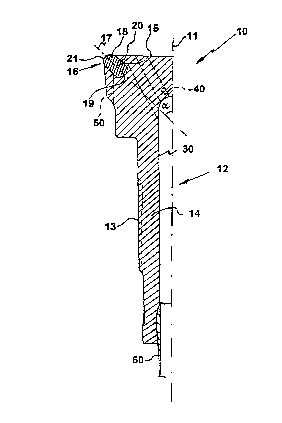
The present invention relates to a percussion drill bit (10) for drilling bores, comprising a steel body (12), means at one end of the steel body for connecting the bit to a percussive unit such as a down-the-hole hammer or a drill string for a jack hammer, a plurality of inserts embedded in the other end of the steel body. At least the peripheral inserts or gauge row inserts comprise a cemented carbide body having a rear mounting portion embedded in the steel body and a front end protruding from the steel body. A polycristalline diamond layer is provided on the front end of the carbide body. The layer has an edge along a border in the vicinity of the maximum diameter of the insert. The edge (22) is kept away a first distance (L1) from the wall of the bore during drilling by tilting the gauge row insert (16) an acute angle (a) of 41· to 51· relative to the rotational axis (11) of the drill bit (10). The invention further relates to a gauge insert, use of a diamond-coated insert as a gauge insert in a drill bit and a method of maintaining the diameter of a drill bit during percussive drilling of a bore in a rock material.


French Abstract

La présente invention se rapporte à un trépan à percussion (10) servant à percer des trous de forage et constitué par un corps en acier (12), un organe situé à chaque extrémité du corps servant à raccorder le foret à une unité de percussion telle qu'un marteau fond de trou ou un train de sonde d'une foreuse pneumatique, une pluralité de pièces rapportées encastrées dans l'autre extrémité du corps en acier. Les pièces rapportées périphériques ou pièces alignées de calibrage ont un corps en carbure métallique dont une partie de fixation arrière est encastrée dans le corps en acier et dont une extrémité avant fait saillie du corps en acier. Une couche de diamant polycristallin recouvre l'extrémité avant du corps en carbure. La couche comporte un bord situé à proximité du diamètre maximum de la pièce rapportée. Le bord (22) est maintenu à l'écart à une première distance (L1) de la paroi du trou de forage au cours du perçage grâce à l'inclinaison de la pièce alignée de calibrage (16) à un angle aigu (a) allant de 41· à 51· par rapport à l'axe de rotation (11) du trépan (10). L'invention se rapporte également à une pièce rapportée de calibrage, à l'utilisation d'une pièce rapportée recouverte de diamant servant de pièce de calibrage dans un trépan et à un procédé de maintien du diamètre d'un trépan au cours du forage à percussion pratiqué dans la roche en place.

Claims

Note: Claims are shown in the official language in which they were submitted.


Claims
1. A percussion drill bit for a drilling bore, comprising a drill body having a
connection section at a rear end for connection to a percussive unit such as a
down-the-hole hammer or a drill string for a jack hammer, and defining a
rotational axis (11) of the drill bit (10) and a plurality of gauge row inserts
(16) embedded in a front end of the drill body, the front end being rigid with
respect to the connecting section, each gauge row insert (16) comprising a
cemented carbide body having a rear mounting portion (20) embedded in
the drill body, and a front end (18) protruding from the drili body, there
being a diamond layer (21) disposed on the front end of the carbide body,
the layer having a rear edge (22) disposed adjacent a maximum cross section
(D) of the insert,
wherein
the gauge row inserts (16) are oriented at an acute angle (.alpha.) relative to a
rotational axis (11) of the drill bit (10) and the angle (.alpha.) is from about 41° to
about 51° for spacing the rear edge (22) of the diamond layer a first distance
(L1) from the wall of the bore (24) during drilling and wherein a portion
thicker than the rear edge determines the diameter of the bore (24).
2. A drill bit according to claim 1,
wherein the front end (18) is curved and defined by a radius (R), an origin (C)
of the radius being disposed axially rearwardly of a plane (P) containing the
rear edge (22) of the diamond layer (21).
3. A drill bit according to claim 2,
wherein the radius (R) of the front end (18) is 50 % to 52 % of a diameter (D)
of the rear mounting portion (20), preferably 50 % to 51 % thereof, and
wherein the distance (L1) is at least 1.5 mm, preferably about 1.7 mm for a
diameter (D) of 18 mm.
4. A drill bit according to claim 1, 2 or 3,
wherein the point of contact between the wall of the bore (24) and the insert
(16) is displaced a second distance (L2) axially forwardly from the rear edge
(22) of the diamond layer (21).
5. A drill bit according to claim 4,

wherein the second distance (L2) is 50 % to 70 % of the radius (R) of the
insert (16), preferably about 60 %, with a maximum diameter (D) of the
insert being of about 18 mm.
6. A gauge row insert for a percussion drill bit of the kind described in claim
1, comprising a cemented carbide body having a rear mounting portion (20)
and a front end (18), a diamond layer (21) disposed on the front end (18) of
the carbide body, said layer (21) having a rear edge (22) situated in the
vicinity of a maximum diameter (D) of the insert (16), wherein the front end
is curved and defined by a first radius (R), and an origin (C) of that radius
being disposed axially rearwardly of a plane (P) containing said rear edge,
the length of the first radius (R) being from about 50 % to about 52 % of the
diameter (D) of the rear mounting portion, a part of said rear edge (22) being
supposed to be passive during drilling and a portion thicker than said part of
the rear edge being supposed to be active during drilling.
7. An insert according to claim 6,
wherein the diamond layer (21) is curved and defined by a second radius (R')
which is in the same magnitude as the first radius (R) of the cemented
carbide front end (18) and wherein an origin (C') of the second radius (R') is
spaced axially forwardly by a fourth distance (L4) from the origin (C) of the
first radius (R).
8. An insert according to claim 7,
wherein the size of the fourth distance (L4) is less than 1 mm but larger than
0.1 mm, preferably about 0.8 mm and wherein the diamond layer (21)
comprises polycristalline diamond (PCD) preferably with a binder content
between 1 % and 15 %.
9. Use of diamond-coated cemented carbide insert as a gauge row insert in a
drill bit for percussive drilling, said drill bit (10) having a rotational axis (11)
and a plurality of gauge row inserts (16) embedded in a front end of the drill
body, the front end being rigid with respect to the connecting section,
wherein the insert comprises a cemented carbide body having a rear
mounting portion and a front end protruding from the rear mounting portion,
a polycristalline diamond layer on the front end of the carbide body, said

layer having a rear edge (22) disposed adjacent a maximum cross section (D)
of the insert,
wherein the front end is curved and defined by a radius (R) and an origin (C)
of the radius is axially rearwardly of a plane (P) containing said rear edge
(22), the gauge row inserts (16) are oriented at an acute angle (.alpha.) relative to a
rotational axis (11) of the drill bit (10) and the angle (.alpha.) is from about 41° to
about 51° for spacing the rear edge (22) of the diamond layer a first distance
(L1) from the wall of the bore (24) during drilling and wherein a portion
thicker than the rear edge determines the diameter of a bore (24).
10. Use of an insert according to claim 9,
wherein the radius (R) is 50 % to 52 % of the diameter (D) of the rear
mounting portion.
11. Method of maintaining the diameter of a drill bit during percussive
drilling of a bore in a rock material, the method comprising the steps of:
- providing a percussive drill body (12) having means (13) at a rear end for
connecting the bit (10) to a percussive unit, and defining a rotational axis
(11) of the drill bit (10), the front end being rigid with respect to the
connecting section, a plurality of gauge row inserts (16) embedded in the
front end of the drill body, each gauge row insert (16) comprising a
cemented carbide body having a rear mounting portion (20) embedded in
the drill body and a front end (18) protruding from the body, a diamond layer
(21) on the front end of the carbide body, said layer having a rear edge (22)
disposed in the vicinity of a maximum diameter (D) of the insert;
- rotating the drill body about a rotational axis (11) such that the gauge row
inserts (16) via portions thicker than the rear edge define a diameter of a bore(24) being drilled, and
- spacing the rear edge (22) of the layer (21) a first distance (L1) from the wall
of the bore during drilling by tilting said gauge row inserts (16) at an acute
angle (.alpha.) of about 41° to about 51° relative to the rotational axis (11) of the
drill bit (10).

Description

Note: Descriptions are shown in the official language in which they were submitted.


CA 02218141 1997-10-14
W 096~7679 1~1/~h~/00622
5 PERCUSSION DRILL BlT, AN INSERT, A USE AND A METHOD OF
MAINTAINING THE DRILL BIT DlAMiETER
Technical background
The present invention relates to a percussion drill bit for drilling bores in
10 rock. A typical percussion drill bit comprises a steel drill body, means at one
end of the drill body for connecting the bit to a percussive unit such as a
down-the-hole hammer or a drill string for a jack hammer, and a plurality of
inserts embedded in the other end of the drill bociy.
15 At least the peripherally located inserts, or gauge row inserts, comprise a
cemented carbide body having a rear mounting portion embedded in the
drill body and a converging front end protruding from the drill body. A
polycristalline diamond layer is provided on the converging end of the
carbide body, the layer having an end edge disposed in the vicinity of the
20 maximum diameter of the insert.
The invention further relates to a gauge insert, use of a diamond-coated insert
as a gauge insert in a drill bit and a method of maintaining the diameter of a
driil bit during percussive drilling of a bore in a rock material.
Known percussive drill bits, e.g. in applicants US-A-5,335,738, that are
provided with diamond-coated gauge inserts often have a disadvantage in
that premature failures occur due to fatigue of the diamond-coating. A reason
for the faiiure is that the point of contact between the wall of the bore and
30 the gauge insert is close, or on, the rear edge area of the diamond-coating.
The coating is very thin at that area and thus has a comparatively poor
resistance to wear. The known drill bits more or less drill the bore diameter
with the thinnest part of the gauge insert since their gauge inserts are inclined
by about 35~ relative to the center axis of the drill bit.
Objects of the invention

CA 02218141 1997-10-14
W 096~7679 PCTISE96/00622
An object of the present invention is to provide a drill bit for percussive
drilling, wherein the life of the bit is extended.
Another object of the present invention is to provide a drill bit for percussive5 driiling, wherein the gauge inserts are angled relative to the rotational axis of
the bit to keep the edge of the diamond-coating away from the wall of the
bore during drilling.
Still another object of the present invention is to provide a drill bit for
10 percussive drilling, wherein each gauge insert ilas a diamond-coating, the
thickness of which varies and wherein a portion of the diamond-coating
thicker than the edge determines the diameter of the bore.
Still another object of the present invention is to provide an effective gauge
15 insert for a drill bit for percussive drilling.
Still another object of the present invention is to disclose an effective use of a
gauge insert for a drill bit for percussive drilling.
20 Still another object of the present invention is to disclose an effective method
of maintaining the diameter of a drili bit for percussive driliing.
These and other objects of the present invention have been attained by a drill
bit, a gauge insert, a use and a method of maintaining the diameter of a drili
25 bit as defined in the appended claims.
Description of the drawings
The objects and advantages of the invention will become apparent from the
following detailed description of a preferred embodiment thereof in
30 connection with the accompanying drawings, and in which:
Fig. 1 shows one half of a drill bit according to the present invention in
longitudinal section; Fig. 2 shows a sectional view of a gauge insert
according to the present invention, in relation to a bore wall; and Fig. 3
shows a gauge insert according to the present invention in longitudinal
3 5 section.
Detailed description of the invention

CA 02218141 1997-10-14
W096~7679 l~ll~h~loo622
In Fig. 1 there is shown one longitudinal haif of a drill bit 10 according to the
present invention, the bit being generally symmetrical about its rotational
t . axis 11. The bit comprises a steel drill body 12 which has external splines 13
on the shank 14 thereof. The splines shall be connected to corresponding
5 splines in a driver sub of a down-the-hole hammer, not shown, so as to
transfer rotational movement in the usual manner. Alternatively the spline
can be replaced by other means, such as threads, for connecting the bit to a
drill string, not shown.
10 The drill bit 10 further includes a central passage 30 for a pressurized
medium such as air, connected to an angled fluid passage 40 which is further
connected to a chipway or return groove 50. A conventional plastic valve 60
is disposed in the passage 30.
15 Provided in the front face 15 of the drill body is a number of button inserts,
not shown. The button inserts are made of cemented carbide and are secured
in borings preferably by press fit.
A number of gauge row inserts 16 are positioned at the periphery of the bit
20 10, the radially outer portions of which define the diameter of the bit and
thus the diameter of the bore being drilled.
The gauge row inserts 16 are tilted in such a way, that a longitudinal centre
line (center axis) 17 of each insert 16 diverges by an angle a from the
25 longitudinal centre axis 11 of the drill bit in a forward direction of the bit.
The tilting of the gauge row insert can also be expressed in such a way that
the point where the longitudinal centre line 17 of the insert 16 intersects the
converging end 18 is located farther from the longitudinal centre axis 1 1 of
the drill bit than the point where the longitudinal centre line 17 intersects the
30 rear end 19 of the insert.
Several gauge row inserts 16 may be embedded in the front end of the drill
body 12. ~ach insert 16 comprises a cemented carbide body having a grip
portion or mounting portion 20 embedded in the drill body and a front
35 converging end 18 protruding from the drill body. A polycristalline diamond
layer 21 is provided on the converging end of the carbide body to define the
cutting end 18 of the insert. The layer 21 has a rear edge 22 substantially

CA 02218141 1997-10-14
W 096~7679 1~/~k~o622
Iying in a plane P, see Figs. 2 and 3, the plane P preferably forming an acute
angle with the center axis 1 1, that angle being equal to the above-mentioned
angle a. The edge 22 is disposed on the cylindrical jacket surface 25 of the
insert at or in the vicinity of the maximum diameter of the insert, preferably
at a junction between a curved front surface of the carbide body, and the
cylindrical jacket surface 25. The longitudinal centre axis 11 of the drill bit
and the longitudinal centre line 17 of the inserts 16 include the angle a
therebetween. The angle a is in the range of about 41~ - 55~, in order to
space the edge 22 by a distance Ll from the wall of the bore 24 during
drilling. More preferably, the angle a is about 41~ - 51~, and most preferably
is about 45~. Such inclination of about 41~ - 55~ results in that the radially
outermost part of the rear edge 22 relative to the axis 11, is supposed to be
pass;ve, i.e. spaced from the wall, during drilling. The distance L1 is at least1.5 mm. For example the distance L1 is preferably about 1.7 mm for an
l 5 insert diameter D of 1 8 mm.
The cemented carbide portion of the converging end 18 is semi-spherically
curved and defined by a radius R Iying on the center axis 17, and the origin
C of the radius R is positioned axially rearwardly of the plane P. The plane P
intersects the centre axis 17 of the insert at a point A. The distance L3
between the point A and the radius origin C is 5 to 30 %, preferably about
20 %, of the radius R. The radius R is about 50 % to 52 % of the diameter D
of the rear mounting portion 20, preferably 50 % to 51 %.
During drilling the point of contact B, see Fig. 2, between the wall of the
bore 24 and the insert 16 is axially displaced by a distance L2 from the edge
22. The distance L2 is 50 % to 70 % of the radius R of the insert, preferably
about 60 % for an insert diameter D of about 18 mm.
The diamond layer 21 has an outer surface defined by a radius R' of the same
magnitude as the radius R of the cemented carbide converging end 18. The
origin C' of the radius R' lies on the center axis 17 and is displaced axially
forwardiy a distance L4 relative to the origin C of the radius R. The size of
the distance L4 is less than 1 mm but larger than 0.1 mm, preferably about
0.6 mm. Thus the thickness of the layer varies from 0.1 mm at the edge to 1
mm at its intersection with the center line 17 (most preferably from 0.2 at the
edge to 0.8 mm at the center line). The diamond layer 21 comprises

CA 02218141 1997-10-14
W 096~7679 ~ 0622
polycristalline diamond (PCD), preferably with a binder content between 1
% and 15 %.
Since the new inventive drill bit will drill longer than hitherto known drill
5 bits it is favorable if the drill body, at least in the vicinity of and around the
gauge row inserts, is provided with a wear resistant coating, such as a hard
metal coating. The thickness of such a coating is preferably about 0.1 mm.
That avoids steel wash-out and thereby prevents the gauge row inserts from
losing steel support and from falling off the drill body.
Drill bits according to the present invention, with a 45~ inclination of the
gauge inserts have experienced 50-70% increased life of the bits compared
to prior art drill bits, with gauge inserts inciining 35~ relative to the rotational
axis of the drill bit.
The present invention further relates to a method of maintaining the diameter
of a drill bit during percussive drilling of a bore in a rock material. The
method comprises the following steps: providing a drill bit having the
geometry described above, connecting the bit to a percussive unit and
20 drilling a bore, while spacing the rear edge of the diamond layers of the
gauge row inserts from the wall of the bore during drilling so as to maximize
the duration of the life of the bit.
The present invention further relates to the use of a diamond-coated
25 cemented carbide insert as a gauge row insert in a driil bit for percussive
drilling.
The invention can be varied freely within the scope of the appended claims.
For example the shape of the cutting end of the insert can be semi-spherical
30 or bullet-shaped.
Although the present invention has been described in connection with a
preferred embodiment thereof, it will be appreciated by those skilled in the
art that additions, deletions, modifications, and substitutions not specifically35 described may be made without departing from the spirit and scope of the
invention as defined in the appended claims.

Representative Drawing
A single figure which represents the drawing illustrating the invention.
Administrative Status

2024-08-01:As part of the Next Generation Patents (NGP) transition, the Canadian Patents Database (CPD) now contains a more detailed Event History, which replicates the Event Log of our new back-office solution.

Please note that "Inactive:" events refers to events no longer in use in our new back-office solution.

For a clearer understanding of the status of the application/patent presented on this page, the site Disclaimer , as well as the definitions for Patent , Event History , Maintenance Fee  and Payment History  should be consulted.

Event History

Description Date
Application Not Reinstated by Deadline 2007-05-14
Time Limit for Reversal Expired 2007-05-14
Inactive: Abandoned - No reply to s.30(2) Rules requisition 2006-06-12
Deemed Abandoned - Failure to Respond to Maintenance Fee Notice 2006-05-15
Inactive: IPC from MCD 2006-03-12
Inactive: S.30(2) Rules - Examiner requisition 2005-12-12
Letter Sent 2005-10-11
Letter Sent 2005-06-17
Letter Sent 2003-06-16
Request for Examination Requirements Determined Compliant 2003-05-07
Amendment Received - Voluntary Amendment 2003-05-07
Request for Examination Received 2003-05-07
All Requirements for Examination Determined Compliant 2003-05-07
Inactive: IPC assigned 1998-01-07
Classification Modified 1998-01-07
Inactive: First IPC assigned 1998-01-07
Letter Sent 1997-12-31
Inactive: Notice - National entry - No RFE 1997-12-31
Application Received - PCT 1997-12-22
Application Published (Open to Public Inspection) 1996-11-28

Abandonment History

Abandonment Date Reason Reinstatement Date
2006-05-15

Maintenance Fee

The last payment was received on 2005-04-19

Note : If the full payment has not been received on or before the date indicated, a further fee may be required which may be one of the following

  • the reinstatement fee;
  • the late payment fee; or
  • additional fee to reverse deemed expiry.

Patent fees are adjusted on the 1st of January every year. The amounts above are the current amounts if received by December 31 of the current year.
Please refer to the CIPO Patent Fees web page to see all current fee amounts.

Owners on Record

Note: Records showing the ownership history in alphabetical order.

Current Owners on Record
SANDVIK INTELLECTUAL PROPERTY AB
Past Owners on Record
BENGT ASBERG
JAN-GUNNAR HEDLUND
Past Owners that do not appear in the "Owners on Record" listing will appear in other documentation within the application.
Documents

To view selected files, please enter reCAPTCHA code :


To view images, click a link in the Document Description column. To download the documents, select one or more checkboxes in the first column and then click the "Download Selected in PDF format (Zip Archive)" or the "Download Selected as Single PDF" button.

List of published and non-published patent-specific documents on the CPD .

If you have any difficulty accessing content, you can call the Client Service Centre at 1-866-997-1936 or send them an e-mail at CIPO Client Service Centre.


Document
Description 
Date
(yyyy-mm-dd) 
Number of pages   Size of Image (KB) 
Representative drawing 1998-01-26 1 8
Claims 2003-05-06 2 89
Description 1997-10-13 5 230
Abstract 1997-10-13 1 54
Claims 1997-10-13 3 139
Drawings 1997-10-13 2 29
Notice of National Entry 1997-12-30 1 193
Courtesy - Certificate of registration (related document(s)) 1997-12-30 1 116
Reminder of maintenance fee due 1998-01-20 1 111
Reminder - Request for Examination 2003-01-14 1 112
Acknowledgement of Request for Examination 2003-06-15 1 173
Courtesy - Abandonment Letter (Maintenance Fee) 2006-07-09 1 175
Courtesy - Abandonment Letter (R30(2)) 2006-08-20 1 167
PCT 1997-10-13 16 686