Language selection

Search

Patent 2218162 Summary

Third-party information liability

Some of the information on this Web page has been provided by external sources. The Government of Canada is not responsible for the accuracy, reliability or currency of the information supplied by external sources. Users wishing to rely upon this information should consult directly with the source of the information. Content provided by external sources is not subject to official languages, privacy and accessibility requirements.

Claims and Abstract availability

Any discrepancies in the text and image of the Claims and Abstract are due to differing posting times. Text of the Claims and Abstract are posted:

  • At the time the application is open to public inspection;
  • At the time of issue of the patent (grant).
(12) Patent Application: (11) CA 2218162
(54) English Title: PRECISION UNIVERSAL CENTRE FINDER
(54) French Title: DISPOSITIF UNIVERSEL DE CENTRAGE DE PRECISION
Status: Deemed Abandoned and Beyond the Period of Reinstatement - Pending Response to Notice of Disregarded Communication
Bibliographic Data
(51) International Patent Classification (IPC):
  • B23B 49/00 (2006.01)
  • B23B 47/28 (2006.01)
  • B23Q 03/18 (2006.01)
  • B25B 05/14 (2006.01)
(72) Inventors :
  • GLOW, HARRY G. (Canada)
(73) Owners :
  • HARRY G. GLOW
(71) Applicants :
  • HARRY G. GLOW (Canada)
(74) Agent: MBM INTELLECTUAL PROPERTY AGENCY
(74) Associate agent:
(45) Issued:
(22) Filed Date: 1997-10-14
(41) Open to Public Inspection: 1999-04-14
Examination requested: 1997-10-14
Availability of licence: N/A
Dedicated to the Public: N/A
(25) Language of filing: English

Patent Cooperation Treaty (PCT): No

(30) Application Priority Data: None

Abstracts

English Abstract


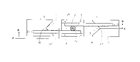
The disclosed invention provides a device for locating the center of an object or an opening, the
device comprising an annular member defining a central hole; opposing centering plates on
opposite sides of the annular member; matching opposed notches in the centering plates, said
notches open towards the annular member, the apexes of said notches being in line with the center
of the central hole and an equal distance therefrom. Arms on the centering plates have gears that
mesh with gears on the circumference of the annular member, so that as the annular member
turns, the apexes of the notches in the opposing centering plates move an equal and opposite
distance along a line drawn through the apexes of the notches and the center of the central hole.
To find the center of the end of a workpiece, the workpiece is placed between the notches which
are drawn together to hold the workpiece, and a pointed pin is placed through the central hole
to mark the center. The device may also be used to scribe a center line on a board or such, and
to find the center of an opening, such as a door or window opening.


French Abstract

Cette invention concerne un dispositif servant à repérer le centre d'un objet ou d'une ouverture et constitué d'un élément annulaire présentant une ouverture centrale, d'une paire de plaques placées de part et d'autre de l'élément annulaire et présentant chacune une entaille s'ouvrant en direction de celui-ci, la pointe de chacune des entailles étant à égale distance du centre de l'ouverture de l'élément annulaire. Aux plaques de centrage sont fixés des bras pourvus de crans qui s'engrènent dans des crans correspondants sur le poutour de l'élément annulaire, de sorte que la rotation de ce dernier entraîne le mouvement des plaques en directions opposées mais sur une distance égale mesurée sur la ligne passant par la pointe des entailles et le centre de l'ouverture de l'élément annulaire. Pour déterminer le centre d'une pièce, on place celle-ci dans l'espace entre les entailles et on rapproche les plaques jusqu'à ce qu'elles la saisissent, puis on insère une pointe dans l'ouverture de l'élément annulaire pour marquer le centre. Ce dispositif peut aussi être utilisé pour tracer l'axe d'une pièce plane, ou pour déterminer le centre d'une ouverture, par exemple une baie de fenêtre ou de porte.

Claims

Note: Claims are shown in the official language in which they were submitted.


- Page 8 -
CLAIMS:
I claim:
1 A device for locating the center of an object or an opening comprising:
a central member defining a central hole;
opposing centering plates being a right centering plate and a left centering plate, said
centering plates being on opposite sides of the central member;
matching opposed notches in the centering plates, said notches open towards the central
member, the apexes of said notches being in line with the center of the central hole and
an equal distance therefrom;
activation means to move the centering plates toward or away from each other such that
the apexes of the notches in the opposing centering plates move, in response to the
activation means, an equal and opposite distance along a line drawn through the apexes
of the notches and the center of the central hole; and
marking means to mark the center of the central hole on the workpiece.
2. The device of Claim 1 wherein the central member is an annular member, said annular
member including engagement means on the circumference thereof.

-Page 9-
3. The device of Claim 2 wherein the right centering plate is fixed to a right arm and the left
centering plate is fixed to a left arm, each said arm having engagement means on a side thereof
meshing with the engagement means on opposite sides of the annular member.
4. The device of Claim 3 wherein the activation means to move the centering plates causes
rotation of the annular central member.
5. The device of Claim 4 wherein the engagement means on the circumference of the annular
central member and the right and left arms is a rack and pinion.
6. The device of Claim 4 wherein the matching notches are straight sided, meeting at an
angle at the apex of the notch such that the line joining said apex with the center of the central
hole and the apex of the other said notch bisects said angle.
7. The device of Claim 6 wherein the angle at the apex of the notches is a right angle.
8. The device of Claim 6 further comprising leading edges on the centering plates adjacent
to the opposed notches, said leading edges being parallel to each other and arranged such that
when the centering plates are moved towards each other, the edges coincide to form a line
through the center of the central hole.
9. The device of Claim 8 further comprising rear edges on the centering plates said rear
edges being parallel and equidistant from the center of the central hole.
10. The device of Claim 8 wherein the centering plates are arranged so that one passes above
the other as the centering plates meet and the apexes move toward the center of the annular
central member.

-Page 10-
11. The device of any one of Claims 1 to 10 wherein the marking means comprises a central
pin, said pin having an outside diameter allowing said pin to slide freely but snugly in the central
hole and said pin tapering at one end to a point, said point being on the axis of said pin.
12. The device of Claim 11 wherein the central pin is a pencil.

Description

Note: Descriptions are shown in the official language in which they were submitted.


CA 02218162 1997-10-14
-Page2 -
- PRECISION UNIVERSAL CENTER FINDER
This invention deals with the field of tools for use in metal and wood-working applications,
carpentry and general construction and more particularly with a device for finding the center of
an object or an opening.
BACKGROUND:
It is a common task in wood and metal working applications to find the center of a workpiece.
The center of an end may be needed for mounting in a lathe, or such. Such workpieces may be
of circular or rectangular cross-section. Present methods often require scribing lines which
intersect at a center point. U.S. Patent Number 4,084,325 to Jones, Jr. also provides a device for
finding the center of circular or rect~n~ r faces.
In construction applications it is common to find the center of an opening, such as a window or
door opening. This is presently done by measuring and mathematical calculation. A center line
might also be needed on a workpiece with parallel sides, such as a board, to allow it to be cut in
half, or to mark holes for dowels and so forth.
It would be desirable to have a simple and economical tool that would accomplish all ofthe above
tasks and at the same time provide a high degree of accuracy.
SUMMARY OF THE INVENTION:

CA 02218162 1997-10-14
- Page 3 -
It is the object of the present invention to provide a simple and economical device that may be
used to find the center ofthe end of a substantially symmetrical workpiece, to scribe a center-line
on a workpiece with parallel sides and to find the center of an opening.
s
It is the further object of the present invention to provide such a device that has the required
degree of accuracy to be useful in all applications.
The present invention provides a device for locating the center of an object or an opening
comprising a central member dçfining a central hole; opposing centering plates being a right
centering plate and a left centering plate, said centering plates being on opposite sides of the
central member; matching opposed notches in the centering plates, said notches open towards
the central member, the apexes of said notches being in line with the center ofthe central hole and
an equal distance therefrom; and activation means to move the centering plates toward or away
S from each other such that the apexes of the notches in the opposing centering plates move, in
response to the activation means, an equal and opposite distance along a line drawn through the
apexes of the notches and the center of the central hole.
DESCRIPTION OF THE DRAWINGS:
While the invention is claimed in the concluding portions hereof, pl~relled embodiments are
provided in the accompanying detailed description which may be best understood in conjunction
with the accompanying diagrams where like parts in each ofthe several diagrams are labeled with
2s like numbers, and where:
Figure 1 is a top plane view of an embodiment of the invention in the open position with
the upper plate thereof removed;

CA 02218162 1997-10-14
-Page4 -
Figure 2 is a cross-sectional view along line AA' in direction B as shown in figure l;
Figure 3 is a top plane view ofthe embodiment of the invention in the closed position with
the upper plate thereof removed;
Figure 4 is a cross-sectional view along line XX' in direction Y as shown in figure 3;
Figure 5 is a bottom plane view of the embodiment of the invention in the closed position,
Figure 6 is a bottom view of the embodiment of the invention in use on the end of a
workpiece of circular cross section;
Figure 7 is a side plane view of the of the same embodiment of the invention in use as in
Figure 6;
Figure 8 is a bottom view ofthe embodiment ofthe invention in use to scribe a center-line
on a board; and
Figure 9 is a top view of the embodiment of the invention in use to find the center of a
window opening.
DETAILED DESCRIPTION OF TIIE EMBODIMENT:
The invention is a device for locating the center of an object or an opening comprising a central
member defining a central hole; opposing centering plates being a right centering plate and a left
centering plate, said centering plates being on opposite sides of the central member; m~tchinu

CA 02218162 1997-10-14
- Page 5 -
opposed notches in the centering plates, said notches open towards the central member, the
apexes of said notches being in line with the center of the central hole and an equal distance
therefrom; and activation means to move the centering plates toward or away from each other
such that the apexes of the notches in the opposing centering plates move, in response to the
activation means, an equal and opposite distance along a line drawn through the apexes of the
notches and the center of the central hole.
Figures 1 and 2 shows one pl~relled embodiment of the invention in the open position. The
central member is an annular gear 1. Gear axle 16 extends beyond the sides of the gear 1, and
o defines central hole 2 along the axis of the gear axle 16. Pin 3 has an outside diameter such that
it is a close fit in the central hole 2 but slides freely in said hole 2. The pin 3 tapers to a point 4
at one end, and is used to mark the center.
Right centering plate 5 is fixed to right arm 6 through right arrn spacer 23 and defines right notch
7. Teeth 8 on right arm 6 mesh with the gear 1, essentially forming a rack and pinion for
transforming rotary motion of the gear 1 into linear motion of the right arm 6, or vice versa.
Sirnilarly left centering plate 9 is fixed to left arm 10 through left arm spacer 24 and defines left
notch 11 and teeth 8 on left arm 1 0 mesh with the gear 1 . The right notch 7 and left notch 11 in
this embodiment are identical opposing notches defining an angle of 90 degrees, with right notch
apex 17 and left notch apex 18 . The thickness of the right arm spacer 23 and the left arm spacer
24 are such that the left centering plate 9 slides just under the bottom plate 13, while the right
centering plate 5 slides just under the left centering plate 9.
The notches are oriented in the centering plates such that the line joining the right notch apex 17
2~ and the left notch apex 18 passes through the center of the central hole 2 and said line bisects the
right angles defined by said notches. The meshing of the gear 1 and the teeth 8 is such that the
apexes 17 and 18 are equidistant from the center of the central hole 2, and as the gearl rotates,
the apexes move an equal distance in opposite directions, and are at all times equidistant from the

CA 02218162 1997-10-14
-Page6 -
center of the central hole.
It is contemplated that a right angle at the apex ofthe notches 17 and 18 will be suitable for most
applications, although it is also contemplated that the angle could be other than 90 degrees and
s still be suitable for various applications so long as the angle of both notches is the same and they
are oriented so as to be bisected by a line drawn through the apexes and the center of the central
hole .
The right and left centering plates 5 and 9 are identical rectangles with the opposing notches 7
o and 11 removed, leaving inner edges 21 parallel with outer edges 22 on each centering plate.
Upper plate 12 and lower plate 13 are fixed in spaced apart relation by spacers 14. Gear 1 is
rotatably mounted between said upper plate 12 and lower plate 13 on gear axle 16 extending
through said plates 12 and 13. Teeth 8 on right arm 6 and left arrn 10 are held in meshing
engagement with gear 1 by spacers 14. Knob 15 is mounted to the gear axle 16, allowing the
operator to turn the gear and thereby move the centering plates 5 and 9 back and forth. The
plates 5 and 9 may also be moved by pushing or pulling, in which case the gear land knob 15 will
rotate in response.
Figures 3, 4 and 5 show the same embodiment in the closed position, where the apexes 17 and
18 ofthe notches coincide with the axis of the gear axle 16.
Figures 6 and 7 show the device in use on the end 19 of a workpiece with a circular cross section
20. The end of the workpiece 19 is placed against the bottom of lower plate 13, and the knob
15 is turned to draw the right centering plate 5 and left centering 9 towards the central hole 2.
When the notches 7 and 11 are firmly in place about the end ofthe workpiece 19, pin 3 is placed
in central hole 2, and may be tapped with a hammer, thereby causing the point 4 to mark the
center of the work piece. Similarly a workpiece with a rectangular cross section would be

CA 02218162 1997-10-14
- Page 7 -
arranged so that the notches coincided with the corners of the workpiece, and the center would
be marked in the same fashion.
Figure 8 shows the device in use to scribe a center-line on a board 25, the flat inner edges 21 of
the right and left centering plates 5 and 9 being drawn snug against the sides ofthe board 25 and
pin 3 inserted into central hole 2 and some pressure is applied to it by hand. The device is then
moved down the length of the board and the point 4 of the pin 3 scribes the center-line of the
board. A pencil could be shaped to fit in the central hole 2 and used to scribe the center-line.
To find the center of a window or door opening 26, the device is placed on the cross piece at the
o bottom of the opening and the centering plates are moved outwards until the flat outer edges 22
of the centering plates 5 and 9 are snug against the outer sides of the opening. Pin 3 is then
inserted into central hole 2 and the point 4 marks the center on the bottom cross piece.
Depending on the size ofthe device, it may be necessary to insert blocks 27 with identical lengths
on each side of the device.
Thus it can be seen that the invention accomplishes all of its stated objectives. The foregoing is
considered as illustrative only ofthe principles ofthe invention. Further, since numerous changes
and modifications will readily occur to those skilled in the art, it is not desired to limit the
invention to the exact construction and operation shown and described, and accordingly, all such
suitable changes or modifications in structure or operation which may be resorted to are intended
to fall within the scope of the claimed invention.

CA 02218162 1997-10-14
-Page 11 -
List of Diagram References
1. annular gear; 16. gear axle;
2 central hole; 17. right notch apex;
3. pin; 18. Ieft notch apex;
s 4. point; 19. end of workpiece;
rightcenteringplate; 20. workpiece with a circular cross
section;
6 r1ght arm;
7. rightnotch; 21. flat inner edges of the centering
plates;
8. teeth;
22 flat outer edges of the centering
o 9 left centeringplate;
plates;
10. Ieft arm;
11. Ieftnotch; 23. right armspacer;
24. Ieft arm spacer;
12 upper plate;
25. board
13. Iower plate;
26. opening;
14 spacers;
knob; 27. blocks.

Representative Drawing
A single figure which represents the drawing illustrating the invention.
Administrative Status

2024-08-01:As part of the Next Generation Patents (NGP) transition, the Canadian Patents Database (CPD) now contains a more detailed Event History, which replicates the Event Log of our new back-office solution.

Please note that "Inactive:" events refers to events no longer in use in our new back-office solution.

For a clearer understanding of the status of the application/patent presented on this page, the site Disclaimer , as well as the definitions for Patent , Event History , Maintenance Fee  and Payment History  should be consulted.

Event History

Description Date
Inactive: IPC from MCD 2006-03-12
Application Not Reinstated by Deadline 2001-10-15
Time Limit for Reversal Expired 2001-10-15
Deemed Abandoned - Failure to Respond to Maintenance Fee Notice 2000-10-16
Application Published (Open to Public Inspection) 1999-04-14
Inactive: IPC assigned 1998-01-06
Classification Modified 1998-01-06
Inactive: First IPC assigned 1998-01-06
Inactive: Filing certificate - RFE (English) 1997-12-24
Application Received - Regular National 1997-12-22
All Requirements for Examination Determined Compliant 1997-10-14
Request for Examination Requirements Determined Compliant 1997-10-14

Abandonment History

Abandonment Date Reason Reinstatement Date
2000-10-16

Maintenance Fee

The last payment was received on 1999-06-21

Note : If the full payment has not been received on or before the date indicated, a further fee may be required which may be one of the following

  • the reinstatement fee;
  • the late payment fee; or
  • additional fee to reverse deemed expiry.

Patent fees are adjusted on the 1st of January every year. The amounts above are the current amounts if received by December 31 of the current year.
Please refer to the CIPO Patent Fees web page to see all current fee amounts.

Fee History

Fee Type Anniversary Year Due Date Paid Date
Application fee - small 1997-10-14
Request for examination - small 1997-10-14
MF (application, 2nd anniv.) - small 02 1999-10-14 1999-06-21
Owners on Record

Note: Records showing the ownership history in alphabetical order.

Current Owners on Record
HARRY G. GLOW
Past Owners on Record
None
Past Owners that do not appear in the "Owners on Record" listing will appear in other documentation within the application.
Documents

To view selected files, please enter reCAPTCHA code :


To view images, click a link in the Document Description column. To download the documents, select one or more checkboxes in the first column and then click the "Download Selected in PDF format (Zip Archive)" or the "Download Selected as Single PDF" button.

List of published and non-published patent-specific documents on the CPD .

If you have any difficulty accessing content, you can call the Client Service Centre at 1-866-997-1936 or send them an e-mail at CIPO Client Service Centre.


Document
Description 
Date
(yyyy-mm-dd) 
Number of pages   Size of Image (KB) 
Description 1997-10-13 7 241
Abstract 1997-10-13 1 26
Claims 1997-10-13 3 70
Drawings 1997-10-13 4 43
Representative drawing 1999-04-25 1 4
Filing Certificate (English) 1997-12-23 1 164
Reminder of maintenance fee due 1999-06-14 1 112
Courtesy - Abandonment Letter (Maintenance Fee) 2000-11-13 1 183
Fees 2002-05-21 1 33
Fees 1999-06-20 1 27