Note: Descriptions are shown in the official language in which they were submitted.
CA 02218469 2006-08-03
1
APPARATUS AND METHOD FOR DETECTION OF LEAKS IN SURGICAL
DRAPES
BACKGROUND OF THE INVENTION
Technical Field:
The present invention pertains to improvements in methods
and apparatus for heating or cooling sterile surgical liquids
and collecting surgical sterile slush. In particular, the
invention is an improvement of the methods and apparatus
disclosed in U.S. Patent Nos. 4,393,659 (Keyes et al),
4,934,152 (Templeton), 5,163,299 (Faries, Jr. et al), 5,331,280
(Faries, Jr. et al), 5,333,326 (Faries, Jr. et al), and
5,457,962 (Faries, Jr. et al).
Discussion of the Prior Art:
The above-referenced Keyes et al patent discloses a
surgical slush producing system having a cabinet with a heat
transfer basin at its top surface. A refrigeration mechanism
in the cabinet takes the form of a closed refrigeration loop
CA 02218469 1997-10-17
WO 96/34572 PCT/US96/05921
2
including: an evaporator in heat exchange relation to the
outside surface of the heat transfer basin; a compressor; a
condenser; and a refrigeration expansion control, all located
within the cabinet. A separate product basin is configured to
be removably received in the heat transfer basin. Spacers, in
the form of short cylindrical stubs or buttons, are arranged
in three groups spaced about the heat transfer basin and
projecting into the heat transfer basin interior to maintain
a prescribed space between the two basins. During use, that
space contains a thermal transfer liquid, such as alcohol or
glycol, serving as a thermal transfer medium between the two
basins. A sterile drape, impervious to the thermal transfer
medium, is disposed between the product basin exterior and the
liquid thermal transfer medium to preserve the sterile nature
of the product basin. Surgically sterile liquid, such as
sodium chloride solution, is.placed in the product basin and
congeals on the side of that basin when the refrigeration unit
is activated. A scraping tool is utilized to remove congealed
sterile material from the product basin side to thereby form
a slush of desired consistency within the product basin. Some
users of the system employ the scraping tool to chip the solid
pieces from the basin side.
As noted in the above-referenced Templeton patent, the
Keyes et al system has a number of disadvantages. In
particular, the separate product basin must be removed and re-
sterilized after each use. Additionally, the glycol or other
thermal transfer medium is highly flammable or toxic and, in any event,
complicates the procedure. The Templeton patent
discloses a solution to these problems by constructing an
entirely new apparatus whereby the product basin is eliminated
in favor of a sterile drape impervious to the sterile surgical
~ . _ CA 02218469 2007-09-19
3
liquid, the drape being made to conform to the basin and
directly receive the sterile liquid. Congealed liquid is
scraped or chipped from the sides of the conformed drape
receptacle to form the desired surgical slush.
The Faries, Jr. et al U.S. Pat. No. (5,163,299) notes that
scraping congealed liquid from the drape is undesirable in view
of the potential for damage to the drape, resulting in a
compromise of sterile conditions. As a solution to the
problem, the patent proposes that the drape be lifted or
otherwise manipulated by hand to break up the congealed liquid
adhering to the drape. Although this hand manipulation is
somewhat effective, it is not optimal, and often is
inconvenient and constitutes an additional chore for operating
room personnel.
The Faries, Jr. et al U.S. Pat. No. (5,331,820) resolves
the problem of manual manipulation of the drape by providing
a method and apparatus to automatically remove the congealed
liquid adhering to the drape without endangering the integrity
of the drape. A flat disk or plate is provided at the bottom
of the basin under the drape. The plate is moved in an up and
down matter to disengage the congealed liquid from the drape.
The plate may be attached to a mechanism below the basin, or
to the drape itself as disclosed in U.S. Patent No. 5,457,962
to Faries, Jr. et al.
Templeton further provides an electrical heater disposed
at the bottom of the basin to convert the sterile slush to
warmed liquid, or to heat additional sterile liquid added to
the basin. Templeton describes the need for such warm sterile
liquid as occurring after a surgical procedure is completed to
facilitate raising the body cavity of the surgery patient back
to its normal temperature by contact with the warmed liquid.
CA 02218469 1997-10-17
WO 96/34572 PCT/US96/05921
4
However, there are a number of instances during a surgical
procedure when it is desirable to have simultaneous access to
both the sterile warmed liquid and the sterile surgical slush.
The Faries, Jr. et al (5,333,326) patent provides a method and
apparatus for simultaneously providing separate surgical slush
and warmed surgical liquid during a surgical procedure using
a single drape for such a unit.
The foregoing patents do not provide a way to prevent
damage to the heating and cooling mechanisms when there is no
liquid present in the respective basins. Further, the
foregoing patents do not provide a way to detect leaks in a
surgical drape. Specifically, when insignificant amounts of
liquid are present in the basins, the heating and cooling
mechanisms operate with little thermal resistance, thereby
making burn out of the mechanisms likely. Another consequence
is that the drapes are damaged by being attached to the heating
or cooling mechanism without having the liquid to absorb the
thermal energy. Since only sterile drapes are to be used
during surgical procedures, a leak in a surgical drape
compromises sterility and contaminates the entire surgical
procedure, thereby increasing the risk of injury to the
patient.
OBJECTS AND SUMMARY OF THE INVENTION
Accordingly, it is an object of the present invention to
provide an apparatus and method to detect the absence of liquid
in a drape used to contain fluid by employing a sensor to
detect moisture.
It is another object of the present invention to detect
leaks in the surgical drape by employing a sensor detecting
CA 02218469 1997-10-17
WO 96/34572 PCTIUS96/05921
conductances, and determining whether the conductances are
within a range indicative of a leak.
According to the present invention, a drape with sensors
is positioned as a drape container in one or more basins on
apparatus for thermally treating sterile liquids such that one
sensor is located in the drape container toward the bottom of
each individual basin. The sensors detect whether liquid is
present in each of the drape containers. A microprocessor
receives the signals from the sensors and prevents thermal
treatment of liquid in drape containers not containing liquid.
In a second embodiment, additional sensors are situated
on the drape at the bottom of each basin below the drape so
that sensors reside on opposite sides of each drape container.
The sensors detect any conductance residing between them in
each individual basin. A microprocessor receives the
conductance from the sensors and determines if the conductance
is sufficient to indicate an electrical path which is
representative of a leak. If a leak is determined to exist,
the microprocessor prevents operation of the basin containing
the leak.
The above and still further objects, features and
advantages of the present invention will be apparent upon
consideration of the following detailed description of the
specific embodiments thereof, particularly when taken in
conjunction with the accompanying drawings wherein like
components are designed by like reference numerals.
= BRIEF DESCRIPTION OF THE DRAWINGS
Fig. 1 is a view in perspective of a surgical slush
machine and surgical drape according to the present invention.
CA 02218469 1997-10-17
WO 96/34572 PCT/US96/05921
6
Fig. 2 is a partially diagrammatic view in elevation and
partial section of the present invention embedded in the
machine of Fig. 1.
Fig. 3A is a more detailed view in elevation and partial
section showing the drape plug connector permanently attached
to the drape.
Fig. 3B is a view similar to Fig. 3A of another embodiment
of the invention wherein the drape plug connector is removably
attached to the drape.
Fig. 4 is a partially diagrammatic view in elevation and
partial section of the leak detection embodiment of the present
invention embedded in the machine of Fig. 1.
Fig. 5 is a view in perspective of a machine containing
both a heating basin and a cooling basin for use with the drape
of the present invention.
Fig. 6 is a view in plan of a surgical drape of the
present invention having particular utility with the machine
of Fig. 5.
Fig. 7 is a view in perspective of the surgical drape of
Fig. 6 deployed on the machine of Fig. 5.
DESCRIPTION OF THE PREFERRED EMBODIMENTS
The present invention can be applied to various
apparatus for providing thermally treated sterile media such
as surgical slush machines, liquid warming and cooling systems,
and multipleunit machines capable of performing both liquid
warming, cooling and slush generation. Fig. 1 illustrates an example of a
surgical slush machine
including a surgical drape implementing the liquid and leak
determination of the present invention. The surgical slush
machine includes a cabinet 10 with a top surface having a basin
CA 02218469 1997-10-17
WO 96/34572 PCT/US96/05921
7
11 mounted thereon in an appropriately sized recess. Basin 11
is made of thermally conductive material, typically stainless
steel, and includes a generally flat bottom wall and a frusto-
conical sidewall. A conventional refrigeration unit (not
shown) is disposed within cabinet 10 and typically includes a
compressor, a condenser and an expansion control unit connected
by appropriate fluid conduits in a closed refrigeration loop
with an evaporator (not shown). The evaporator is in the form
of a coil wound about the exterior surface of basin 11 in
thermal transfer relation therewith. When the refrigeration
unit is activated by means of an appropriate on-off controller
15 and temperature adjustment control 16, the evaporator cools
the sidewall of basin 11 to a temperature substantially below
the freezing temperature of the liquid used in forming the
sterile slush. A sterile surgical drape 17, preferably
transparent, is disposed over the top and sides of cabinet 10
and made to conform to the side wall and bottom of basin 11.
The on-off controller 15 and temperature adjustment control 16
are disposed on the top surface of cabinet 10 and are
adjustable/controllable manually through drape 17. The portion
of surgical drape 17 disposed in the basin serves as a sterile
receptacle or drape container for sterile liquid placed therein
to be frozen into the described sterile slush.
Drape 17 has a sensor 14 that preferably is affixed
thereto and is preferably positioned toward the bottom of basin
11. The sensor may, if desired, be located at a predetermined
height above the basin bottom and, thereby serve as a liquid
level detector. Sensor 14 is connected to cabinet 10 by way
of a drape plug connector 13 plugged into a cabinet receptacle
connector 12. The surgical slush machine only operates when
drape plug connector 13 is plugged into cabinet receptacle
CA 02218469 2006-08-03
8
connector 12. Sensor 14 in the preferred embodiment is
permanently affixed to the drape by adhesive, ultrasonic
welding, or any other suitable manner or means, typically at
the time the drape is manufactured. Removable sensor
arrangements may also be used.
When the surgical slush machine is in operation, the
sterile liquid in the drape receptacle freezes in pieces on the
surgical drape covering the sidewalls of the basin. A mechanism
for automatically removing the frozen pieces from the surgical
drape is disclosed in U.S. Pat. No. 5,331,820. In that patent
the drape container sides are moved up and down automatically
to loosen attached pieces of frozen saline.
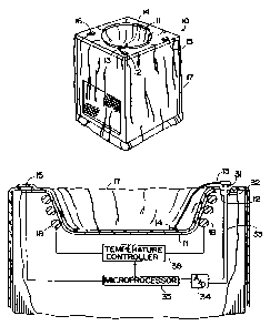
Fig. 2 illustrates in greater detail the liquid detection
apparatus of the present invention used in a surgical slush
machine. Specifically, drape 17 is deployed in basin 11 so as
to cause sensor 14 on drape 17 to be positioned generally
toward the bottom of basin 11. Drape plug connector 13 plugs
into cabinet receptacle connector 12 to couple sensor 14 to a
microprocessor 35, via A/D converter 34, to enable operation
of the machine. Microprocessor 35 controls electrical
application of power to a temperature controller 36 based on
an analysis of signals from sensor 14. Temperature controller
36 controls operation of the refrigeration system, including
evaporator 18, to adjust the temperature of liquid in basin 11
according to temperature adjustment control 16 (Fig. 1). Power
switch 15 controls power to the surgical slush machine.
Sensor 14 comprises two leads between which electrical
conductance is measured. If liquid is not present between the
leads then zero or insignificant conductance is measured and
a signal indicating such is sent to microprocessor 35.
CA 02218469 1997-10-17
WO 96/34572 PCT/US96/05921
9
Alternatively, the sensor may be implemented in fiber optics
whereby optical properties of the sensor measurably vary
depending upon its placement in liquid. The sensor detects
optical conductivity changes and sends a corresponding signal
to microprocessor 35.
In operation, sensor 14 detects the presence or absence
of liquid and sends an analog signal to A/D converter 34 via
drape plug connector 13. Specifically, drape plug connector
13 is a conventional plug containing pins 31 received in
sockets 32 of cabinet receptacle connector 12. Sockets 32 are
connected to wires 33 to carry the signal to A/D converter 34.
A/D converter 34 converts the analog sensor signal into a
corresponding digital signal suitable for application to I/O
pins (not shown) of microprocessor 35. If drape plug connector
13 is not plugged into sockets 32 of cabinet receptacle
connector 12, microprocessor 35 ultimately receives no signal,
or a low amplitude signal, from sensor 14, which is equivalent
to zero or insignificant conductance, and inhibits application
of power to temperature controller 36. Microprocessor 35
analyzes the converted digital sensor signal, containing either
conductance or optical properties, in order to determine if
liquid is present in basin 11. If microprocessor 35 determines
liquid is not present, microprocessor 35 disables electrical
power to temperature controller 36 to prevent damage to the
drape and cooling mechanism.
Referring to Fig. 3A, drape plug connector 13 is
permanently attached to drape 17 by insertion through an
opening in drape 17 surrounded by seals 37. Seals 37 insulate
drape 17 to maintain sterility (i.e., to assure no
contamination of the sterile field at the exposed surface of
the drape). Alternatively, Fig. 3B illustrates drape plug
CA 02218469 1997-10-17
WO 96/34572 PCT/US96/05921
connector 13 being removably attached to drape 17. Drape plug
connector 13 is inserted through an opening in drape 17 and
attached to drape 17 by snap buttons 38 and is affixed to a
holder 40 containing the snap buttons 38 on opposite sides.
Snap buttons 38 are inserted into snap receptacles 39 mounted
on drape 17 to extend therethrough from opposite sides of the
drape at the location where drape plug connector 13 is
inserted. Snap receptacles 39 are insulated by seals 37 to
maintain sterility of drape 17. Snap buttons 38 and snap
receptacles 39 are conventional snap fasteners. Seals 37 may
be made of rubber, urethane, silicone, epoxy, acrylic or any
other material capable of functioning as a seal to insulate
drape 17.
As noted above, sensor 14 may be positioned to serve as
a liquid level detector, in which case the liquid in the drape
container must be present at the sensed level to permit
operation of the system.
Fig. 4 illustrates a second embodiment -of the present
invention. Specifically, an additional sensor 19 is employed
on the drape so that conductance is measured between sensors
14 and 19 residing on opposite sides of drape 17. Sensor 19
is preferably permanently affixed to drape 17 in the same
manner as described above for sensor 14. Sensors 14, 19
measure such conductance and send a signal to A/D converter 34
via drape plug connector 13 through cabinet receptacle
connector 12. Drape plug connector 13 may be permanently or
removably attached to drape 17 as described above. A/D
converter 34 converts analog sensor signals to digital signals
for use by microprocessor 35 in analyzing the measure of
conductance. The measured conductance signifies whether an
electrical path between sensors 14 and 19 has been established,
CA 02218469 1997-10-17
WO 96/34572 PCT/US96/05921
11
indicating the presence of a leak. If microprocessor 35
determines a leak is present, microprocessor 35 disables
electrical power to temperature controller 36 to prevent
compromise of liquid sterility and prevent damage to the
cooling mechanism.
The embodiments of the present invention are not limited
to a single heating or cooling basin. Several heating, cooling
or slush basins may be connected for use with a drape varying
in size to accommodate all the basins. An example illustrating
such multiple basins is shown in Fig. 5. Specifically, an
integral assembly 50 includes a cooling basin 42 for slush and
a warming basin 43 for liquid recessed into the top surface 44
of a common cabinet. Also disposed within integral assembly
50 are cooling unit power switch 45, a cooling unit temperature
controller/indicator 46, a heater power switch 47, a heater
unit temperature controller/indicator 48, an A/D converter 34,
a microprocessor 35, and cabinet receptacle connectors 12 for
receiving sensor data.
A sterile surgical drape 51 suitable for covering the
entire top surface 44 and to provide drape containers for both
basins 42 and 43 is illustrated in Fig. 6. Drape 51 has
sensors 14 attached thereto with corresponding drape plug
connectors 13. Drape plug connectors 13 are inserted through
openings in drape 51 and are permanently or removably attached
to drape 51 as described above. Drape 51 has two centering
marks or indicia 52, 53 adapted to be placed over the centers
of the cooling and warming basins 42 and 43, respectively,
during installation of the drape.
Fig. 7 illustrates the centering indicia 52, 53 properly
positioned when drape 51 is pushed down into respective basins
until the drape conforms to the basin shapes. Sensors 14 are
CA 02218469 1997-10-17
WO 96/34572 PCTIUS96/05921
12
positioned toward the bottom of basins 42, 43 with drape plug
connectors 13 plugged into their corresponding cabinet
receptacle connectors 12.
Operation of the liquid detection embodiment of the
present invention in the multiple basin machine is
CuhQtantlally s.~..m~lar t-o the embodiment d cjtribed Cibo''e far
Fig. 2. Referring to Figs. 5, 7, microprocessor 35 receives
digitally converted sensor signals from sensors 14 via A/D
converter 34. Microprocessor 35 determines the basins which
do not possess any liquid (or wherein the liquid is not at a
minimum predetermined level) based on the conductance
measurement of the individual sensors 14, and disables power
to only those temperature controllers 46, 48 corresponding to
basins where no liquid is present. If a drape plug connector
13 is not connected to cabinet receptacle connector 12,
microprocessor 35 receives a signal level representing zero or
insignificant conductance from corresponding sensor 14 and
power is disabled to the basin whose drape plug connector 13
is not connected.
Leak detection in the multiple basin machine is
substantially similar to the embodiment described in Fig. 4.
Referring to Fig. 7, additional sensors 19 (not shown) are
deployed on drape 51 and positioned at the bottom of basins 42,
43 such that each basin contains one sensor on respective
opposite sides of the drape (Fig. 4). The conductance between
sensors 19, 14 is measured and the sensors in each basin send
a measurement signal through A/D converter 34, to
microprocessor 35. Microprocessor 35 determines which
conductances from each basin are determinative of a leak, and
subsequently disables power to the temperature controllers
corresponding to those basins where a leak has been detected.
CA 02218469 1997-10-17
WO 96/34572 PCT/US96/05921
13
If a drape plug connector 13 is not connected to cabinet
receptacle connector 12, microprocessor 35 receives zero or
insignificant conductance from corresponding sensor 14 and
power is disabled to the basin whose drape plug connector 13
is not connected.
The surgical drapes for all of the above machines are made
of material that is impervious to the heated and cooled sterile
liquid and slush, and is sufficiently soft and flexible to
conform to the walls of basins. Typically, by way of example
only, the surgical drape is made of materials commonly used in
hospitals for drapes. The drapes may also be made of
polyurethane film as disclosed in the aforementioned Templeton
Patent. The surgical drapes are designed to be disposable
after a single use to assure sterility for each surgical
procedure, and are provided pre-sterilized and pre-packaged in
a leak proof plastic bag or other sealed container to preserve
the sterile nature of the surgical drape during storage.
Microprocessor control is accomplished by software
providing conductance determinations and comparisons. The
microprocessor may be implemented by virtually all commercially
available microprocessor chips as known in the art.
It will be appreciated that the embodiments described and
illustrated in the drawings represent only a few of the many
ways of implementing detection of liquids and leaks of drape
containers in the present invention.
The microprocessor of the leak detection embodiment of the
present invention may be utilized to account for absorption of
the sterile liquid by the drape material forming in the drape
container. For some drape materials this absorption is
significant and increases the conductance measured by the
sensors through the drape, even though there is no leak, and
CA 02218469 1997-10-17
WO 96/34572 PCT/US96/05921
14
produces false detections of leaks. The microprocessor may be
supplied with liquid and drape material specific hydration
tables for the drape to adjust sensitivity of the
microprocessor to the conductance measurements and reduce the
amount of false detections. Hydration characteristics of drape
materials, as a function of time, are known and can easily be
programmed into the microprocessor.
The function of the microprocessor may be accomplished by
general circuitry, combinational logic or any other switching
means used to disable power.
The present invention may include sound or visual
indicators notifying when the absence of liquid or a leak is
present. Such indicators include an alarm, buzzer, colored
light, speech synthesizer or any other indicator used for
specifying a condition or state of an object.
The drape plug connector of the present invention may be
implemented with various numbers and types of pins, dependent
upon the desired resolution or accuracy of the measured
conductance. Alternatively, the drape plug connector may be
implemented using sockets plugged into corresponding pins in
the cabinet receptacle connector to yield the same results.
The drape plug connector of the present invention may be
removably attached to the drape by any means capable of
fastening the drape plug connector to the drape.
Although the preferred embodiment discloses sensors
containing electrical leads and fiber optics, any sensors for
measuring conductance or presence of liquid may be implemented
according to the present invention.
From the foregoing description it can be appreciated that
the invention makes available a novel method and apparatus for
detection of liquid and leaks in surgical drapes by measuring
CA 02218469 1997-10-17
WO 96/34572 PCT/US96/05921
and analyzing conductance. In addition, the invention prevents
operation of the machine if either the absence of liquid or a
leak has been determined to exist.
Having described preferred embodiments of the new and
improved method and apparatus for detection of liquid and leaks
in surgical drapes, it is believed that other modifications,
variations and changes will be suggested to those skilled in
the art in view of the teachings set forth herein. It is
therefore to be understood that all such variations,
modifications and changes are believed to fall within the scope
of the present invention as defined by the appended claims.