Note: Descriptions are shown in the official language in which they were submitted.
CA 02218~63 1997-10-16
Ba( k~round of the Invention
The invention relates to a method of and a system for obtaining, storing
and displaying the conditions of a web moving at high speed, such as a paper
web, for analysis purposes. In particular, the invention relates to a method
and system utilizing video cameras for obtaining visual displays of a moving
web for the purpose of analyzing and determining causes of web failures and
breaks, including the recording, storing and displaying of such information
through the use of video tape recorders in a surveillance system that permits
recorded visual information on the web to be output in either or both of a
visual format via video display monitors or in a computer format via a
computer monitor andtor by other computer media such as printers, floppy
discs, hard drives, RAMs, etc.
In making paper, a continuous web of material is passed over a
plurality of rolls. The web is formed from a slurry of bleached pulp fibers,
clay, starch, various additives and water. The slurry is received from a
headbox by one or two endless wire screens, where it is formed into a
relatively wide uniform sheet that is dried between a plurality of rolls and
eventually wound onto reels in the form of large paper rolls. The continuous
web may have a width on the order of 25 feet, and the forming process utilizes
both heat and pressure to form a relatively thick mass of the slurry into a thin
layer of dry paper wound onto a reel at the exit end of the paper machine.
During the forming process, the continuous web encounters a variety of types
CA 02218~63 1997-10-16
of rolls and tension control devices. Such devices include initial heat drying
drums, drum rollers, thickness reduction rollers and, in the case of high gloss
papers, supercalender rollers.
Where a continuous web of material such as paper is processed as a
continuous length of material from beginning to end, maintaining the integrity
of the web is critical to the continued operation of the process. However,
since defects and imperfections in the web occur from time to time, and
because the papermaking equipment itself can get out of calibration, web
failures occur. In addition, the continuous web moves quite rapidly, so when
a break in the web occurs, it happens very rapidly and, even if viewed in real-
time, the cause of the break often is not apparent. Thereafter, if may be
extremely difficult to determine the exact cause of the web failure. Although
devices exist to monitor the continuity of the continuous web and to shut down
the paper machine quickly should a web break occur, such devices do not aid
in determining the actual cause of web failure.
An important step in improving paper machine runnability is to pinpoint
where web breaks are occurring, so that the cause of the break can be
corrected. However, determining the exact location of a web break is
becoming more difficult as machine speeds increase. Heretofore, various
attempts have been made to capture the conditions of a moving web for later
analysis, which attempts include recording the passage of a continuous web of
paper on video tape that can subsequently be replayed and analyzed to allow
CA 02218~63 1997-10-16
inspection of the web to be carried out separately from the real-time web
processing. One such exemplary system is disclosed in U.S. Patent No.
5,239,376, assigned to Lake Superior Paper, Inc., a subsidiary of Consolidated
Papers, Inc., the assignee of the present invention, and the teachings of which
are specifically incorporated herein by reference. In the system taught by said
patent, a plurality of video cameras are utilized to capture a series of events
taking place generally simultaneously on and along a web of paper traveling
through a paper machine. The events are recorded on a plurality of video tape
recorders, one for each camera. When an event such as a web break occurs,
the recordings made by the video recorders can be displayed on a plurality of
video monitors, with two camera outputs being linked on split screens of a
single monitor for visual analysis by an operator to determine the cause of the
web break. So that one of the split images on a monitor screen will not "roll"
while the other image remains constant, the plurality of video cameras are all
commonly time synchronized. In analyzing the split images on one or more
monitors, the operator may note that a small tear may have first been initiated
in the web at a certain position in the web (in a cross web direction) and at a
certain camera location (for example, near the wet end dryers), and then
deduce that such tear was the principle cause of the web break. This type of
analysis provides the operator with an excellent indication as to where to first
look on the machine for the cause of the web failure and therefore the cause of
the web break, which significantly shortens the time required to determine the
CA 02218~63 1997-10-16
cause of the break and in turn greatly reduces downtime of the paper machine
and the return of the machine to production, resulting in very significant cost
savings. Even a few minutes reduction in downtime of a paper machine
incident to such breaks, or a reduction in the number of breaks as a result of
an ability to quickly and accurately determine and correct the cause of a break,
is of great economic value, as downlime cost on a large paper machine can be
on the order of $90,000 per hour.
Each time the paper web fails, the papermaking process is interrupted
while the cause of the breakage is determined, any necessary equipment
repairs made, and the continuous web rethreaded so that the machine car~
resume operation. The downtime required is very expensive as the entire
papelnlaking process comes to a standstill, so minimi7ing downtime is a very
important consideration. Rapid diagnosis of the cause of web breakage or
failure is therefore critical with respect to the time it takes to conduct any
necessary repairs and restore the paper machine to full operation.
A video surveillance system that can monitor the continuous web of a
papermaking machine in a manner such that when a break occurs, the interval
just prior to the break can be replayed to determine the probable cause of web
failure, has remained a definite need with respect to the operation of paper
machines. While the video surveillance system of said patent no. 5,329,376 is
very useful and valuable, it requires a relatively large number of monitors for
a given number of video cameras to display the visual information and can
CA 02218~63 1997-10-16
present such information only in a video monitor-video recorder format.
Further, during playback there can be an instability of the visual display in the
form of jitter that results from the video tapes in the video recorders being
mechanically driven.
Objects of the Invention
An object of the present invention is to provide a web surveillance
video system that visually monitors and records the continuous web of a
~a~el,l,aking machine, so that when a web break occurs the interval just prior
to the break can be replayed to determine the probable cause of web failure.
Another object is to provide such a web surveillance video system in
which multiple video monitors with simultaneous multiple view capability are
used to display the replayed images.
A further object is to provide such a system in which recorded video
information about the web, as output by video tape recorders, is time base
corrected during replay to elimin~te jitter of the image(s) on the monitors.
Yet another object is to provide such a system that includes conversion
of a replayed analog video signal to a digital computer dat~b~ce format for
storage and subsequent retrieval and analysis.
Summary of the Invention
The present invention provides a web surveillance video system for
monitoring a continuous web of material moving along a path of travel through
a papermaking machine. The system comprises a plurality of video cameras,
-
CA 02218~63 1997-10-16
each for addressing a different location of interest of the web along its path of
travel through the papermaking machine and for producing a video output
signal. Included are a plurality of video recorders, each for receiving at an
input thereto and recording on a video tape, and for playing back and
producing as an output signal, the video output signal from an associated one
of the video cameras. The system has at least one video monitor, as well as
means for coupling the video recorder output signals to the at least one video
monitor to selectively displaying on the at least one video monitor either an
image from a single one of the video cameras or a sequence of images from
more than one of the video cameras. To provide a jitter-free image on the
video monitor or to at least substantially reduce jitter, also included are means
for time base correcting the video recorder output signals that are coupled to
the at least one video monitor. In addition, the system includes means for
receiving and responding to an independent alerting signal that indicates the
occurrence of a web event to be reviewed and for causing the video recorders
to cease recording upon occurrence of the alerting signal, so that the event can
be reviewed on the at least one video monitor.
In a preferred embodiment, computer means are provided for
controlling operation of the system. The event to be reviewed is a failure of
the continuous web, and to provide on the video monitor a clean, jitter-free
image of the failure, the means for time base correcting the video recorder
output signals causes horizontal syncs of the signals to occur at uniform
CA 02218~63 1997-10-16
intervals. The means for coupling the video recorder output signals to the at
least one video monitor comprises at least one quad for receiving four video
recorder output signals and for reformatting the four signals into a single video
output signal that is coupled to the at least one video monitor for display of the
four images in quadrant fashion. The system has computer means for storing
in digital form at least a selected portion of the video output signal for
subsequent retrieval and analysis.
The invention also contemplates a method of monitoring a continuous
web of material moving along a path of travel through a papermaking
machine. The method comprises the step of generating a plurality of video
signals representative of images of the continuous web at selected different
locations of interest of the web along its path of travel through the
papermaking machine. Also included are the steps of recording each video
signal on an associated video tape; generating an alerting signal upon
occurrence of a web event to be reviewed; interrupting the recording step in
response to generation of the alerting signal; and generating playback video
signals, following interruption of the recording step, by playing back at least
the most recently recorded portions of each video tape. In addition, included
are the steps of time base correcting the playback video signals, and displaying
on at least one vidéo monitor an image represelltative of one or more time
base corrected playback video signals.
CA 02218~63 1997-10-16
In a preferred practice of the method, the step of generating a plurality
of video signals generates at least one group of four video signals, so that the
time base corrected playback video signals comprise at least one group of four
such signals, and included is the step of reformatting each group of four
playback video signals into a single playback video signal. The displaying step
comprises selectively displaying on a video monitor associated with each
reformatted playback video signal either an image in quadrant fashion that is
repleselltative of the four separate views of the web that have been reformatted
into the single playback video signal, or a full screen image that is
Iepl~sentative of any one of the four separate views. The preferred practice
also includes the steps of printing a recorded video frame of interest as
displayed on the video monitor, and using a computer to control performance
of the method. So that web failures may later be reviewed, at least a portion
of each reformatted playback video signal may be selectively stored for
subsequent retrieval and analysis.
The foregoing and other objects, advantages and features of the
invention will become apparent upon a consideration of the following detailed
description, when taken in conjunction with the accompanying drawing.
Brief Des~ tion of the Drawin~c
The single drawing figure is a block diagram representation of a web
surveillance video system according to the invention.
CA 02218~63 1997-10-16
Detailed Description
During manufacture of a continuous web of paper, disruptions can
occur that result in failure of the paper web and lost production.
Consequently, an important step in improving paper machine runnability is to
pinpoint the location in the paper machine where web failures occur.
However, determining the exact location of a web failure has become
increasingly difficult as machine speeds increase. The use of video equipment
to monitor and record the web during manufacture has been found to provide
valuable information that facilitates determining the precise location and cause
of paper web failures, thereby minimi7ing downtime of the paper machine.
The web surveillance video system of the present invention improves upon
known video surveillance systems and results in a more rapid and accurate
determination of the cause of a web failure and a reduction in downtime of a
papermaking machine incident to web failures.
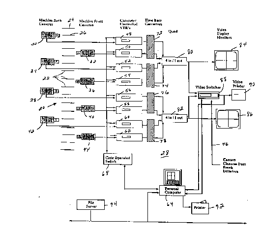
The drawing shows a schematic layout of a papermaking machine.
indicated generally at 20, in which the wet section or initial web forming
portion of the machine is at the top of the drawing and the final finished paper
section is at the bottom. The paper machine includes a plurality of rolls 22
including an initial center roll 24 and a press roll 26.
Also shown in the drawing is the web surveillance video system of the
invention, indicated generally at 28. The system includes a plurality of video
cameras, such as eight video cameras 30, 32, 34, 36, 38, 40, 42 and 44,
-
CA 02218~63 1997-10-16
located on the back and front sides of the paper machine at selected strategic
locations along the path of travel of a continuous paper web through the
machine. The video cameras may be Panasonic Model WV-CP612 cameras,
and provide a means for representing views of the web, at the selected
locations, as electronic signals. While eight video cameras are shown, more
or less may be used, the number employed being generally in accordance with
the number of locations in the paper machine where web failures are most
likely to occur. A plurality of conventional sheet break detectors (not shown)
as are customarily used with a papermaking machine and that monitor the
continuity of the paper web in a well-known manner provide a signal on a
cable 46 upon occurrence of a break in the continuity of the web.
As the video cameras are normally located close to the moving web and
within the confines of the papermaking machine itself, they are exposed to ~he
extreme conditions utilized in forming, rolling and drying the web. Each
camera must therefore be protected from a hostile environment of relatively
high temperatures and humidity, and for the purpose each camera is contained
within an enclosure (not shown) that provides mechanical protection for the
camera and, as the need requires, thermal protection also.
A video output signal from each video camera, which for the particular
cameras used is an analog signal, is coupled to an input to an associated one of
a plurality of video tape recorders 48, 50, 52, 54, 56, 58, 60 and 62. Each
video recorder provides a means for recording onto a video tape the analog
CA 02218~63 1997-10-16
video signal representative of the image of the web viewed by its associated
video camera and for subsequently replaying the recorded signal. Each video
recorder may comprise a Panasonic Model AG-6730 video recorder, and each
has a communication port that allows it to be controlled by a separate signal
source. In the video surveillance system of the invention, the communication
port of each video recorder is connected to be controlled by a personal
computer 64, which may be an IBM compatible ESE 486DX2 personal
computer. The personal computer provides foundation for control of the video
surveillance system by providing communications to other system components,
to interface points between the user and the system, and to the environment
where various control and interface programs reside. Control signals
developed by the personal computer are applied through a code operated
switch 68 to the communication ports of the video recorders. The code
operated switch supports communication in the video surveillance system by
allowing a single computer communication port to individually address a
multitude of output ports connected to the communication ports of the video
tape recorders. The code operated switch may be a Black Box COS-16.
Analog video output signals from the video tape recorders are coupled
to inputs to time base correctors 72, 74, 76 and 78, which may comprise Feral
model LC 4:2:2 devices. Each time base corrector receives the output signals
from two video recorders. The outputs from the video recorders 48 and 50
are coupled to the time base corrector 72, the outputs from the video recorders
CA 02218~63 1997-10-16
52 and 54 are coupled to the time base corrector 74, the outputs from the
video recorders 56 and 58 are coupled to the time base corrector 76, and the
outputs from the video recorders 60 and 62 are coupled to the time base
corrector 78. The time base correctors enhance video displays developed on
video monitors during playback by the video tape recorders by elimin~ting
jitter in the displayed images. They do this by time base correcting the analog
video output signals from the video recorders by means of synchronizing each
frame of video display that is output from each video recorder to a uniform
1/30 of a second time base. In operation of the time base correctors, a signal
received from a video recorder is stored for a period of one frame, i.e., for
two vertical sweeps of a raster, following which the stored frame is written out
with new timing information. Essentially, the time base correctors cause the
horizontal syncs of the output signals from the video recorders to always occur
at the same uniform time interval, i.e., at the 1/30 second interval of a frame.
This advantageously corrects timing errors that occur in the output signals
from the video recorders. Ideally, a horizontal sync would occur in the output
signal from a video recorder at 1/30 second intervals. However, because a
video recorder uses a mechanical drive for a video tape, variations occur in the
speed at which the video tape is mechanically driven, resulting in variations in
the intervals between the horizontal syncs in the video recorder output signal.
The time base correctors elimin~te such variations by causing the horizontal
sync interval to always be 1/30 second. This, in turn, provides a jitter free
CA 02218~63 1997-10-16
image on a video monitor to which the video recorder output signal is applied,
even during freeze frame viewing.
Outputs from the time base correctors 72 and 74, which are the time
base corrected analog video output signals from the video recorders 48, 50, 52
and 54, are applied as inputs to a quad 80. In a like manner, outputs from the
time base correctors 76 and 78, which are the time base corrected analog
video output signals from the video recorders 56, 58, 60 and 62, are applied
as inputs to a quad 82. Each quad 80 and 82 may be a Panasonic model WJ-
420 quad, and each reformats the four separate time base corrected analog
video input signals at its inputs into a single analog video output signal that is
coupled as an input to an associated video monitor 84 or 86. Each quad is of
the switched type and can be controlled so that all four video signals at its
inputs are simultaneously presented at its output as a single reformatted video
output signal that shows all four views for display by its video monitor in
quadrant fashion, or so that only a selected one of the views contained in the
single reformatted video output signal is presented at its output for full screen
display by its video monitor. The video monitors 84 and 86 may be of the
Panasonic model CT-2084Y type, and depending upon the switched setting of
the quads 80 and 82, will display all four views from their associated video
recorders in linked quadrant fashion, or will display only a single selected one
of the views.
CA 02218~63 1997-10-16
The outputs from the quads 80 and 82 are also coupled to inputs to a
video switcher 88, which may be of a type sold by Panasonic as model WJ-
SQ508. An output from the video switcher is coupled as an input to a video
printer 90, which may be of a type sold by Panasonic as model AG-EP50.
The video switcher is a multi-purpose device that can be controlled to send just
one of a plurality of video input signals to a designated location, e.g., to an
input to the video printer 90. The video switcher can also be controlled to
provide for processing of external alarms, such as occur on the cable 46 from
a web break detector, and to communicate with other electronic equipment,
such as with the personal computer 64. The video switcher is operable, for
example, to develop at the input to the video printer 90 an analog signal from
the quad 80 or 82 that is representative of a single video frame developed at
the output from a selected one of the video recorders, with the video printer
then being operable to generate a hard copy image of the video frame. The
video switcher also is coupled to the personal computer 64, which can have an
associated printer 92. The personal computer is therefore adapted not only to
control the operation of the web surveillance video system 28, but also to
receive video signals from the video switcher and to generate hard copy
rel)lese~ltations of the same on its printer 92, or to utilize the video printer 90
as otherwise desired. The surveillance system may also include a file server
94 that is coupled to the personal computer and a frame grabber utilized by the
CA 02218~63 1997-10-16
personal computer to accommodate storage of information for later retrieval
and analysis.
Video cables are employed to carry video signals throughout the
surveillance system, and may be provided with high temperature jackets and
protected from electrical and mechanical interference to the extent necessary.
A patch panel (not shown) may advantageously be used to facilitate
configuration and reconfiguration of the system.
An operator can readily control the web surveillance video system 28.
The view displayed by each monitor 84 and 86 is determined by switches on
its associated quad 80 or 82, such that a monitor can simultaneously display in
its four quadrants four views as represented by the four video signals then
being input to its associated quad, or just a selected one of the four views.
The video tape recorders 48, 50, 52, 54, 56, 58, 60 and 62 are conveniently
controlled by using a mouse and selecting "buttons" on the monitor screen of
the personal computer 64 that correspond to tape direction, speed and record
or playback. If desired, the video images can also be displayed on the
personal computer monitor. Also, since the video printer 90 is in-line with the
computer display, status information on the video printing process may be
provided on the computer monitor, and a selection may be made by mouse
between the quads 80 and 82 to route selected signal groups to the computer.
The computer program used to operate the system is based upon Panasonic's
Proteus for Windows PFW-300. The Panasonic Proteus System is configured
16
CA 02218~63 1997-10-16
to result in the specific commands needed by the surveillance system to
respond to alarm conditions and to support convenient and easy operator
control of the system. The particular configurations are flexible and
reconfigurable, and depend upon factors such as the number of cameras, alarm
types to be processed, desired control functions, hard copy options, system
security needs, and the like.
The web surveillance video system 28 is designed to gather video
information from a large number of remote locations and to efficiently
concentrate the information. For example, by developing groups of four views
at the four quadrants of each of the video monitors 84 and 86, and by enabling
convenient switching between a quad-view and a single-view on a monitor, an
operator can quickly isolate the view of choice in the quad-view, and then
switch to a single-view for detailed inspection of a web failure site.
Advantageously, the video monitors have large screens, so that the quad-views
have the same detail as they would have if displayed on a smaller monitor
using a single-view system, and so that a single-view presents considerable
detail. Concentration of the gathered information is assisted by the video
switcher 88, which enables an operator to select between the quads for the
signal to be presented to the video printer 90. The concentrating ability of the
system also allows all of the video recorders to be simultaneously controlled,
so that all of the quad-views on the monitors are linked and move relative to
each other in time, which enables the sequence of views to be moved forward
CA 02218~63 1997-10-16
or in reverse without disrupting the time relationships between the various
views.
Web failures resulting in web breaks are items of interest for the
surveillance system 28, so the web break detectors already conventionally
employed on the paper machine provide a convenient independent alerting
signal source to indicate a web break and shut down the video recording
process. This capability of responding to the paper machine web break
detectors is provided between the software package and the video switcher 88
that receives indications of web breaks over the cable 46.
In operation of the web surveillance video system 28, the video
cameras 30, 32, 34, 36, 38, 40, 42 and 44 send analog video signals
comprising electronic representations of their views to their respective video
tape recorders 48, 50, 52, 54, 56, 58, 60 and 62 during the normal operation
of the papermaking machine. At this time, all of the video recorders are
operated in the record mode to record on their video tapes the analog video
signals represen~ing continuous images of the paper web at the locations of the
video cameras along the path of travel of the web through the paper machine.
The video recorders run continuously, except during routine rewind operations
or upon occurrence of a web break condition.
Upon occurrence of a web failure as indicated by the independent web
break detection system of the paper machine, an alarm signal is generated on
the cable 46 and is registered at the video switcher 88, which in turn directs
18
CA 02218~63 1997-10-16
the personal computer 64 to stop the recording process. All of the video
recorders then stop and wait for an operator to attend the system. Because the
web break is usually detected downstream from the actual web failure location,
it is likely that one or more of the video cameras will have seen the failure
occur.
To analyze the occurrence of web failure, the operator uses a mouse to
acknowledge the alarm. The operator then uses the mouse to activate
"buttons" on the computer display to move the video recorder tapes forward or
backward at normal speed, at speeds reduced with respect to normal, or frame
by frame, to observe the web failure from where it origina~ed all the way
through the machine. At this time, operating the quads 80 and 82 to display
quad-views on the video monitors 84 and 86 allows the operator to observe
linked views of the web run in the forward or reverse direction at all camera
locations. The view of interest is located by using the speed and direction
controls with the video displays. Once the particular view of interest is
determined, i.e., the-view showing the beginning of web failure, the quad-
view on the appropliate monitor is replaced with a single-view of the view of
interest, so that detailed analysis of the view can be performed. A hard copy
image of the video view of interest can also be obtained by means of the video
printer 90, and the status of the printing operation can be made available by
calling up the video display onto the computer display. While displaying the
recorded images either at normal speed, at speeds reduced with respect to
19
CA 02218~63 1997-10-16
normal, or in a frame by frame manner, the time base correctors 72, 74, 76
and 78 time base correct the video signals output by the video recorders in
such manner that the viewed image(s) on the video monitors 84 and 86, and
any hard copy print provided by the video printer 90, are jitter-free. This
unique feature of obtaining a jitter-free image by means of the time base
correctors greatly enhances the ability of the operator to see and thereby to
quickly and accurately locate and determine the cause of web failure. Once
the web break analysis is completed and the paper making process restarted,
the operator restarts the recording process by using the mouse on the computer
display. The web surveillance process is then repeated.
The ability to review the critical period just prior to and during web
failure at selected viewing speeds and directions and with jitter-free video
displays of the web provides the input necessary to more rapidly evaluate the
location and cause of the failure, so that any necessary adjustments and/or
repairs can be undertaken quickly and the paper machine restored to normal
operation in a reduced time. If only a defect in the paper web is to blame
this, too, often will show up, thereby saving the time that would otherwise be
spent inspecting the paper machine for the cause of the failure. Thus, through
use of the web surveillance system of the invention, considerable savings may
be realized by reducing downtime of the paper machine.
While one embodiment of the invention has been described in detail,
various modification and other embodiments thereof may be devised by one
CA 02218~63 1997-10-16
skilled in the art without departing from the spirit and scope of the invention,
as defined in the accompanying claims. For example, while the surveillance
system as described utilizes components that generate analog output signals,
the invention could also be practiced with components that generate digital
signals.