Note: Descriptions are shown in the official language in which they were submitted.
CA 02218812 1997-10-21
MOBILE COMPUTER AND SYSTEM
This invention relates to mobile, user-supported CO~ JU~cl~ and, more specifical}y; to
a computer col,lponent connection means utili~in~ fiber optics. This application is a
Continu~tion- In-Part of Serial No. 08/538,194 filed in the U.S. Patent and Trademark Office
on October 2, 1995.
Bacl~round of The Tnvention
In parent application serial no. 08/538,194 (Newman et al I), a user-supported mobile
l0 computer is disclosed and claimed. Newman et al describes various embodiments of the
mobile co~ ul~l including various activation means including audio activation means, eye-
tracking activation means, electroencephalography activation means (EEG), head and arm
tracking means all used alone or in any combination of these. Newman et al I also describes
the use of fiber optics to connect any of the cû~ onelll~ of the hands-free COIII~JULCI
15 apparatus described therein. Using the general system of Newmal et al I, each of these
activation means may replace the voice activation of the coll.ulcl-,ial embodiment ~lcsenLly
used by Xybernaut Corporation. The Mobile Acsict~nt (~) as commercialized by Xybernaut
Corporation utilizes state of the art voice activation means.
Each of these stated activation means are in electrical connection wlth a transducer
and converter means. The con~l Licl means are in collllllullication with the processor means
for receiving comm~n~s from the user and for converting the activation coi."..~..tlc into
electrical signals. There is also present means for recognizing any co,.. ~ lc from any
activation means, collvc;l Lillg these to electrical signals to the processor means. The
tr~nccl~lcer and con~llel means may or may not be ~u~pollcd by the user. The computing
a,u~u~l~lus further includes display means in communication with the processor means for
cceivillg information from the processor means and for displaying the l~ ceivcd information
for the user. The display means (HMD) is fully :iU~)~JUI ted by the user. The user may operate
CA 02218812 1997-10-21
the computing a~Jpalalus to display information in a hands-free manner uhli7inE any of the
brain, eye, audio, head or arm tracking activation means. Each of these activation means are
described in detail in parent application serial no. 08/538,194. In ~ lition, while it is
coll~ ,lated in Newman et al that all of the Co~ )o~ can be housed in a single housing
such as in the headset, at the present, the Mobile ~c.cict~nt (E~) uses electrical connPcting
cables to connect each component to the other. All of the above-noted colllpollellL~ of the
present system including the processor, activation means, display means and power means,
may be contained in one housing such as the head-llloullt~d display unit.
The use of some of the portable conll,ollclll~ of the present a~Jpdlalus with a remote
host computer is also a possible embodiment. Since the colll~ul. l component of Newman et
al I is the heaviest COIlll)ul~cll~, an embodiment of the present invention includes using only
the: (a) activation means (voice, eye tracking, brain-activation and/or other activation
means), (b) headset with the display in electrical coll~ u"ication with a processor means for
receiving the outputted inforrnation from the ~locessol and for displaying the received
infommation for the user, and (c) a commlmication means such as a transceiver Utili7ing
radiofrequency, dispersed or directed infrared, ultrasonic or other modlll~t~d carrier waves
for tr~ncmicsion of infommation bcl~e~.l the activation means and the host col~ el and
acc~hlg retum infomlation from the host COIll~)U~tl. The remote co",~ul~, can be in contact
with several users con.;ull~ ly each having activation means, headset with display means
and comm-mication means to interact with the host co",~ l. Th~lefulc, in this second
mode, it is possible, for example, to pemmit several users with h~ otc to function off one
portable mobile host culll~ul~l carried, WORN OR SUPPORTED by one of several users
either working together or at remote locations. Another embodiment incul~ulat~;~ the
processor and communication means within the housing of the display means. Head and arm
tracking can also be used in conjunction with the afule.ll. .llioned activating means. Head
and arm tracking is primarily used to indicate to the COIIIIJUI~1 the position of the head and
CA 02218812 1997-10-21
one or more arms or legs if required, relative to a CO~ JUlt~l display which contains
representations of the user's appendages. This is frequently used in virtual reality
applications in which the user is l~resc,.~d in the display or can affect the display by
appendage movements. These appendage tracking signals reflect appendage position and
affect the conl~ulel program and display as though the user is a part of the programmed
events. Articles described use and design of head and arm tracking devices can be found in
m~g~7in~s such as Virtual Reali~y-Sl~ecial Report, Winter 1994, Vol. 1, Number 4. In this
report, head and arm tracking are described in the article "Is Virtual Reality a Good Teaching
Tool?" on page 51. In addition, tracking devices of the type used in this embodiment can be
obtained from Exos Inc., 2A Gill St., Woburn, Mass. And other suppliers as listed in
Virtual Reality Resource Guide of the above publication. Examples are, the Exos "Force
Arm Master" and the Exos "Position ArmMaster". The Position ArmMaster is advertised as
"A tr~ncd~ll er of human arm motions that provides comm~n-l.c to the slave or simulation and
15 can be used to record human motions". Essentially, head and arm tracking devices contain
tr~rlcd~lcers that provide signals relative to the position of the head and the arm vertically and
ho,i~ol.l~lly relative to predetermined planes of reference. The plans are three-dimensional
and describe a point in space relative to the person wearing the tracking devices and a point
in space relative to a computer simulation. These transducers are coupled to circuits for
receiving and h~ g the trancducer signals such as are available from DigiSonic, Inc.,
P.O. Box 407, Old Greenwich, CT. The use of such technology along with a user-su~ ed
voice, eye tracking, or brain actuated co.. ,uul~. presents a new e.. vi.~.. ~,nl for computing
that will be revolutionary for present and future applications. C~,--.~ollents to accomplish
head and arm tracking are available to the technician and are ~;u~ lly in use for games and
virtual reality e.luip...e..l.
CA 02218812 1997-10-21
In the modes described above, the system would work as follows:
In the first mode, a user having a headset with activation means a display screen and
commlmication means is l*lked with a host cû~ either wom on the user's person
cont~in~d with*n the display means or remote from the person. The user would culllu,dlld the
5 host co,l,~ul~l to display a particular procedure for r~ pai~ g a piece of e4u;llllle~ The host
co~ ul~l would then search for and tl~nslllil the procedure back to the user for display on the
user's headset.
In the second mode, a host co"",uL . could also be l~ ol-~ivc to several users having
10 h.oa-l~ets that may be wolhing as a team to repa* the piece of c.lu;l...ll -t. The users could all
work from the same procedure or call for a dirrtlci"l ~ùcedu~c to be displayed as an
additional window in the display. In this manner, team lllelllb~l~ can also use the system as a
communication means between team members as a fomm of int~lcc,...,...~ications as well as a
means to co".pa,c; findings using the graphic display capabilities of the system. It may be
15 that infommation required by the team is cont~ined in several host coll~ lel~. The
communication means in each headset is then c~ nfi~red and tuned so that several hosts can
be made available to each headset as well as several hPa.1cetc operating into one host.
Obviously, the present system will function with cû..~po.. .~c of several mobile
CGIII~IIillg ap~.a,~lus interacting with each other. As in examples above, the headset of one
mobile Cûlll~uh,l can receive displays from other mobile sets or can INlTIATE the
activating means of another mobile collll~ul~
A further feature of an embodiment of the present invention utilizes an adapter used
in each mobile computer to permit the use therein of cellular or hal~lwil~; telepholle
co,.. ~ ication. In place of the cellular teleph~n~ co.l.. - .ication means a radiofrequency,
infrared, laser or fiber optic L,~nsc~iv~, or other co"""u"ication means may be used. These
will generally be referred to in this disclosure as commllniration means". Cu~ u~ication
means can be accPssed through the host computer or by using the headset with its built-in
CA 02218812 1997-10-21
co..~ iC~tion capability. Thus, communication can be between headsets, headsets and host
CO~ JUlt;l., and between host computers activated by headsets as the control devices. A
scenario of operation would be with a team of users repairing a tank or railroad engine. The
host cu,~ ler unit is su~J~o"ed on the body of the team leader. The other team members
activate the host computer using their headsets. One team member requires information
stored on a host colllyllle~ located back at the l"A;,~tf .~nce shop two miles from the repair
site. This team ~ bc~ acquires the remote host Co"",.ll~, at the m~intt~n~nce shop using
this headset communication means and a cellular telephone link. The information required is
10 refe~nced and viewed on his headset. After obtaining the correct reference material, it is
downloaded to the repair site host for other team members to utilize by viewing it in their
h.o~tlcetc Thus, local as well as remote hosts can be activated by team Illclll~ ' headsets.
Information can then be obtained from remote hosts and downloaded to the local host
computer or, conversely, updated from the local host to the remote (m~int~n~nce shop) host.
Team members can communicate among themselves using headset-to-headset
communication links and to host or remote computers as required. Local communications
can use varied means of linking h~lcetc to host and headset to headset. Dispersed infrared
is useful as a medium for local linking because of c aves~llo~"~ing security potential, b~n-lr~cs
width, low co...l-o~ cost and communication reliability.
The following are various embo~iim~ntc that may be used when the hands-free
computer of the present invention is used having all co".~ollc"ls in the headset portion of the
apparatus:
A. Wireless Headset to Host Computer - A user alt~,."~.ling repair of a complex machine
such as an aircraft is equipped with a head or body mounted display having a wireless
communication link with a computer portion of the Mobile ~csist~nt(g) The user is
wearing the computer unit on a waist belt and, for example, is wearing a headset unit.
The lack of wiring between the headset and the user-supported computer allows free
CA 02218812 1997-10-21
movement of the user's head and arms without regard for t~ngling wires or cn~gging
them on nearby objects. During the repair the user must crawl into a small opening. At
this point, the user removes the cc,~ )ul~ l unit and places it outside the small open~g
before ~LIc~ g to wiggle into the opening. Since the headset to host cn~ ication is
wireless co"""~,ir~tion, control of the host collll,ul~. is still possible. The user would
issue voice comm~n~c to the host colll~,ul~. or position the cursor and evoke comm~n-lc
with an eye tracking eyepiece.
B. Wireless Several Headsets to a Host Collll,ul~l - A team of ".~;"I.~ e personnel is
10 performing "~ -re checks on an aircraft. Each member of the team is equipped with a
Mobile ~Cci.ct~nt@) headset having wireless cc"""""ic~tion linkage to a Mobile ~ccicpnt~
host COlll,UUl~ U~JpOI led on the body of the team leader. Each mPmher of the team is able to
commnnicate and activate various functions of the host colllluulc.. If dirrclcl,l data is
required by various members of the team, each would utilize a sc~alate ~lcse~ tion window
15 for their data. In addition, each headset has circuitry that allows cc..",.~ .;cation btl~
headsets for intcl-;~""""~ tions. This is accomplished by ~witcllillg to that mode using
voice co.",..~ lc or by acli~ating proper icons on the user's headset display using eye
tracking capabilities as installed in the headset.
C. Wireless Cullllll~lication to Other Hosts Remote From the Team Location - C-)ntinning
the above scenario, a lll~lllbel of the ~"~;"l~ re team above IC~IUilC;~ data located on a
computer remote from the team location. The remote colll~,ulel is displaced geographically
from the ..,~;"te~ ee team location. This displ~cemPnt could be several miles or several
thousand miles from the team location. Options for that team lll~lllb~ l are:
Radiofrequency - Link with the remote host culll~ul~l using wh~lc~ radiofrequency
communications bel~ ~ n the headset of the team member and the team host co",~ul~, to the
remote host computer and return data back through the team cc lllpulcr then to the headset of
the requesting team member. All Ill~.llb~ .~ of the ".~;"I-o"~ e team could receive the retum
CA 02218812 1997-10-21
data from the remote co~ ,ulel or by using discrete user headset addressing, limit the retum
data to the l~.lue~lillg headset. This is accomplished using radiofrequency transceivers
commllnicating between the host and remote modems. In practice, the radiofrequency
transceivers would use packet modems for the data tr~ncmic.cion be~ ,.l the host and remote
computers. In digital radiofrequency wireless cùll.lllullications, packet tr~ncmic.cion is used
to assure reliability of data transfer by error checking and lcLu~ c~ csion since hllt,r~.. ,lce
and fading are common problems in radiofrequency data transfer.
D. Cellular Telephone - Another option would be to use a cellular telephone link b~,LWeell
the local host colll~ and a remote COlll~uLtl The ll,~ r.~ e team member requiring
the remote data uses a wireless headset to link with the local team host COlll~ultl. This is
accomplished by the ~"A;~ e team lll~,.llbel using a wireless headset and voice or eye
tracking activation means to dial a local cellular telephone through a digital data-to-telephone
modem at the local host computer. This establishes a tclephone link with the required remote
computer. The link then uses ccll~ c.~;ial telephone lines to contact the required remote
computer at its hal.lwil~,d or cellular telephone number (local or long fiict~nre). The remote
computer using its digital data-to-telephone modem establishes a modem to modem
connection with the local host co,ll~llel and data trancmiccion is active. The local
m~intt-n~nce team member using the wireless headset can now request digital data from the
remote computer.
Other trancmiccion means - Other options for cul,l"l.l.licating with a remote
computer could include laser or other communication methods that would have the required
range and reliability for data transfer. The scenarios for such linkages would be similar to
2 5 the above.
It is obvious that all commlmications between Mobile .Accict~nt~) (a registered
trademark of Xybemaut Corporation, of Fairfax, Virginia) components using various
CA 02218812 1997-10-21
wireless means could also be conducted using l~dwile or fiber optic connections but fiber
optics are the ~ ;fc~lcd connection means as earlier noted.
This co~ ation means would be e,.L~.llely helpful to the user to order parts,
update remote Colll~Ju~ t~b~ses or convey other illfolllldtion while using the mobile
computer of this invention. Thus, the user does not need to detach him or herself from the
mobile COlll~ul,- to call a parts supplier or c~ nclllt~nt to assist at the task at hand. This type
of collull~lication hookup may be accomplished as follows.
The CGlll~uleld~J~JdldluS of this invention may be interfaced with a telephone system
in such a way as to provide hands-free tcl~ho~-e c~ icatiQn belweell multiple persons
and/or co~ ulcla. One or more of these may be p~ g tflc~h~ s colll~llullications by
using the present colll~ul~lappdldlus. As earlier noted, co...,,~ ,;cations may include but are
not limited to~ I l wall jacks commonly found in homes and small l ~ ses multiple
line telephone switching systems found in ~"r.l;ll." and large l,~ Fssec, cellular
communications, radio frequency co"",~ l;on~ interfaces and cordless ~ccec~v.ies to any
of the above.
The basic system incoll,uldles the d~aldlus of this invention, i.e. hands-free body-
wom coll-pulel with voice activation and a head-mounted display, a tcltpholle system and a
unique elc.;llonic interface between the two that illlcgldl~:a both traditional analog voice
signals and CGIIl~ul~l data b~ e.l the two cn",~ ,L!i
Integration of private as well as public tcl~phone col,.~ ,;c~tions into this system is
accomplished using a voice/data modem (modlllator/~etnolllll~tor) as now used with existing
computing systems. The modem is either built-in to the host colllpuh. or it can be inserted
as a "PCMCIA" or "PC Card" into the host Culll~u~ . In addition, collulluu~ication means in
the headset can also utilize a built-in modem to interface through co.l.l~ ,;cations means to
a remote device. Using the cn,."".,~,ication means for the system, data and voice can be
CA 02218812 1997-10-21
transmitted and received bc~ n h~lcetc and mobile systems as well as between mobile
systems.
Cu~ c~ting co~ ul~l graphic images, still or motion video, may utilize-a
co".,..-...ication system such as cellular radio or hdldwilc systems. Such systems can, if
n~ces.c~ry, operate using multiple channels, data cc""~re;,aion or both which will enable
tr~n.cmicsion of the above-mentioned data at near real time or real time speeds. The host
COIIl~u~cl will be used to c~ l;cate with another co,ll~.ule~ at a remote location. Each
COl11lJUIC1 will serve users having h~ lcetc that will display data and images and serve as
activating devices to control the host COlll~ h.a. For example, if cellular telephones are used
as a wireless colll....~l;c~lion means, the Colll~)ulcl would access the telephone number of a
remote host co,ll~ulel, cellular or otherwise, and establish a co""e~;tion. When data
trancmiccion bcL~ ~., host COIll~ulcla is ,~lui,~d, the user switches to data mode through a
voice/data modem installed in the local host computer to establish data tr~ncmiccion. The
15 dialing and ~wilcllillg sequences can be controlled by voice or other activation means by the
host O~(,ldtOI. This allows for the passing of voice input signals from the a~Jdldlus of this
invention through to the teleph- n~ system while m~int~ining voice-activated co",~ul~.
control of the host through the telc~.hone system. This interface may be integrated within the
computer al~pdldlus of this invention, att~rh~d to it during m~nllf~cture or user installed.
This a~"oach provides se~mllos.c awil~,lLIlg b~ lwccll voice and data trancmiccion and
reception b~L~ell one or more distant locations without distracting from the task being
,~.r~"",ed by the individual using the computer a~lldldlus of the present invention.
It goes without saying that the mobile colll~-ll. . of this invention may be interfaced
with or used in c~ e~;lion with any desired colll~ul~. local llclwo~h~ such as Novel, Banyan
or Arcnet or wide area ll~,lWUl~i such as "Intemet" or the like.
This allows for the passing of voice input signals from the a~J~dldlua of this invention
through to the telephone system while 11~ g voice-activated COlll~ul~,- control of the
CA 02218812 1997-10-21
telephone system. The interface may be illlc~laled within the CG~ ul.,. apparatus of this
invention, attached to it during m~nnf~cture or user installed. This a~,u,oach provides
se~mlPcc ~wil~hing between voice and data tr~ncmicsion and reception between one or mare
distant locations without distracting from the task being ~.rollllcd by the individual using
the computer al.p~alu~ of the present invention.
The present system of ~ L.li,lg audio and video signals in the Mobile ~Ccict~nt~
to internal or external colllpol~ or devices is to utilize multi-wire electrical cables. These
cables have a number of disadvantages such as: inflexibility, snbst~nti~lly heavyweight,
10 bnlkin~occ susceptibility to i"l~.r~.c.,ce and colll~alalivcly high costs. Rigid cables are
somewhat difficult to work with especially when connected to the HMD.
Sllmm~y of The Inv~ntion
It is therefore an object of this invention to provide a user-~up~,ollcd mobile
computer devoid of the above-noted disadvantages.
15Another object of this invention is to provide fiber optic means to replace at least a
portion if not all of the electrical cables used in a mobile colll~ul~. system.
Another object of this invention is to provide a mobile co",~ul~. system having
greater reliability and lower probability of i"l.,.Ll~.lce because of the use of fiber optics.
Still a further object of this invention is to provide a user-~u~,uul led mobile colll~uh~-
having a substantially lighter weight than those previously used.
Yet a further object of this invention is to provide a user-~u,u~ol lcd mobile Colll~
wherein the headset is .cignifi~ntly reduced in size due to the substantial reduction of the
weight of wiring used.
25Still another object of this invention is to provide a lighter, more reliable user-
supported mobile colll,u~ . that requires ~-b~ lly less power co,.~ ,lion.
Yet still a further object of this invention is to provide a ~ub~ t;~lly lighter HMD
that-can be more comfortably wom by the user.
CA 02218812 1997-10-21
These and other objects of this invention are accomplished by a mobile col.~ulcl
having fiber optics in at least a portion of its conll,ollcnt connections, in particular the
connection b~,t~ el~ the HMD and the processor. The system of this invention comprises a
computer housing, means for attaching said collll~ul~l housing to a user, means for activating
said computer in a hands-free manner and a CCillllJUl~,l display means such as a head-mounted
display. The hands-free activating means used in the present invention is selected from the
group consisting of audio activation means, eye-tracking activation means,
electroencephalography and l~ UIcs thereof. These activation means may be used with
lO other hands-free activation means if desired such as pen activation, head and arm tracking
means, etc.
The device or system of this invention may be used with each of the systems
~pal~luses or methods disclosed in parent application serial no. 08/538,194. The fiber
optics or fiber optics bundle used in this invention is the type disclosed in U.S. Patent Nos.
l 5 4,657,346; 4,741,584; 5,345,529; 5,400,424 and 5,461,683; the disclosure of each is
inco,~ tedby Icç~.ence into this disclosure.
Mobile colll~ lcscnlly utilize heavy multi-wire cables for transferring audio
and video signals from a body worn collll)ule. to the display or pcli~h~.al devices. In mobile
computers, especially the headset, weight of the unit is an ilnp(Jllallt factor. Anything that
reduces the weight or size of a mobile COIIII)UIe~ iS critical. Cables used in today's mobile
computers comprise at least 35% of the weight of the HMD unit. Since the HMD is worn for
a considerable amount of time, a ~ignific~ reduction in weight by the use of fiber optics
HMD-processor collne-;lions is c~LIclllcly desirable. Traditional cables used to ll~llslllil or
deliver video signals to computer monitors or head mounted displays (HMD) are generally
thick bundles of heavy wire. These wires are very inflexible and cumbcl~,l,.e to use since
the user of a mobile colllpul~. must not only support these wires but must also arrange them
so as to not interfere with the hands-free operation and nature of the system. In terms of
CA 02218812 1997-10-21
ergonomics, balance of the HMD is critical for users who wear a head mounted display over
a long period of time. The weight of the cable causes the HMD to pull to the side where the
cable is att~h~d to the HMD thus making the device unstable and lmb~l~n~ed In most head
mounted display systems, all components nFct~ . y to view an image are actually
implement~d into the HMD. This includes optics for making the image appear much larger
than the actual size of the display, the display itself, the backligh~ (typically used in active
matrix liquid crystal displays), and the electronics that are used to convert ~l~nda,d VGA
analog signals into a format that the LCD can display. It is col,l~."plated that any suitable
display means may be used in the present invention, for example, other all~lllalives to LCD
can be used such as electroll....i.-Fscient displays and the like. Also, as noted in this
disclosure, co",l,ol,el~ls usually found in an HMD such as b~Clflightc optics, display means
or driver electronics may be located elsewhere in the mobile colll~ l.,. system. It is also
within the spirit of this invention to include within the present system any suitable display
15 means with or without any co",pol,c.,l usually found in the HMDs used today.
The impl~ ..F .I~l;on of these displays can be in llulllelulls configurations but, for the
most part, all co"~ponel,l~ are usually cc~ i..rd in the HMD. The problems with this type of
implem~nt~tion are as follows:
1. Weight and the distribution of that weight is critical to the success of a Head Mounted
Display. The weight must be distributed evenly so that a user who wears the HMD for
çxtendç~l periods of time does not end up with undue strain to the neck. However, in
most HMD systems, the bulk of the weight is carried on the front part of the head.
Companies, in an effort to cou,,l~,l,alance the weight, have either moved the elc~ l,onics
2 5 or added a cou"te.l,alancing weight to the back portion of the head. (Note: Even though
the developer is adding weight to the system which is contrary to the mission of reducing
the overall weight of the HMD, tests have shown the overall effect is that the unit feels
CA 02218812 1997-10-21
lighter due to the distribution of the total weight over the entire head as opposed to just
the front part of the head.
2. Ergonomics also play a part in the overall acceptability of an HMD system. Studies ha~e
shown that a user becomes self-conscious when wearing an HMD.
An embodiment of the present invention would involve implemPnt~tion of the fiberbundle where all the major CO~ Ol~ ce~ y for displaying information to the user that
are traditionally found in the head lllou"led display system would now be cont~ined in the
processor housing; that is, the optics, the liquid crystal display (LCD), the bac~ ht and the
driver clc.,~ "ics for the LCD. As earlier noted, any suitable HMD with or without any of
these components traditionally found in HMDs can be used in the system of the present
invention. The ",echallism for delivering the information (image) from the co",pult;,
(processor) to the user would be a fiber bundle that is attached to the optics inside the
processor housing to special glasses or other display means that the user wears. Another
15 embodiment would be modification of traditional co"~ ~,liv~: glasses the user wears so that the
image is reflected on the inside portion of the lens (the side of the lens closest to the user's
eye). This would allow the size and weight of the head mounted display to be reduced to the
physical size of the fiber bundle and the glasses n~ceS.~ y to reflect the image.
A head mounted display such as disclosed in co-pending application serial no.
08/779,265 used for both single and group viewing may also be used in the system of this
invention.
Benefits include the reduction in the weight of the head mounted display (since the
conventional components are now in the pr~,cessor housing), the size of the physical device is
smaller~ less intrusive to the point where the user could wear the head mount~d display and
not be obvious to a uninformed observer and the elimination of electrom~En~otic i"te,r~ .~nce.
In body worn applications, it is not desirable to have cabling protruding or cables
positioned away from the user's body. This is because wiring not close to the user's body
CA 02218812 1997-10-21
tends to get entangled on objects while the user maneuvers around e4..;r.l..~nt This places
the user as well as the system at risk of injury. Ideally, the the cable should conform to or be
positioned as close to the user's body as possible so as to l--;--i--1;7~ the risk of entanglement
on adja~ent objects. A-itlition~lly, these wire cables tend to be heavy and inflexible due to
their multi-layer configuration. When these heavy wire cables are bundled together for
proper usage in a mobile co,ll~uler, obviously, the weight becûllles significant. Thus, due to
the number of wires, the insulation coating of these wires and the multiplicity of wires
n~cec~ry to deliver illfol ~ ;on to the monitor or HMD, it would be very desirable if a light,
more flexible and more effective ~II.s~ for these bundles can be provided.
The use of a fiber optic link to co---,---~-ic~te video infoll~ ion from the Colll~ult:l to
the Head Mounted Display elimin~t~s all of the above-noted problems. Other fiber optics
linkage to internal colll~ùne,ll~ and external accec~olies may also illl~JlU~., these connections.
The specifics of the present system follows the system disclosed in parent application
serial no. 08/538,194, the disclosure of which is h~coll.ù-~ted into the present disclosure by
reference.
Any suitable type of fiber optics may be used as the connPction means used to
deliver video signals in the present invention; fiber optics link~gec such as used in telephone
communications, in TV tr~ncmicsion or TV Cable T,~ ."ic~ion may be used if suitable. As
noted earlier, typical fiber optics useful as c~ o~ in the present invention are described
in U.S. Patent Nos. 4,657,346; 4,741,584; 5,345,529; 5,400,424 and 5,461,683.
Brief Descr~tion of Th~ DrawiT~
Figure I is a side view of a CUIIIIJUl,r housing ~~o--t~ g a lulucesso, used in a
2 5 mobile, user-~ulll,u, l~d CC Ill~u~ system using co.. ~e.. lional electrical cables.
Figure 2 is a side view of a co---~uhl housing co..~ a ~-ucessor used in a
mobile, user-~u~,~u.l~d con,~ul~, system using fiber optics cunne~,lions of the present
invention.
14
CA 02218812 1997-10-21
Figure 3 is a top perspective view of the body-wom CU1~I~JU~ with the fiber optics
connection which will run from the colll~ulel housing to the head mounted display.
Figures 4 and 5 are schPm~tic views of the user-~ulJ~olled system of the present
invention illustrating the use of fiber optics to connect the housing to the HMD.
Figure 6 is a p~ ,e-;livc; view showing an embodiment of the present invention
where most major compo~ necessary for displaying infommation are cont~inPd in the
processor housing.
Description of The Drawin~ and P~ d Fmhotlim~nt~
In figure l, the collll,uh l 1 similar to that of this invention is shown from the side
except that figure l shows the prior art connections of inflexible electrical wiring, whereas
figure 2 illu~llales the same co...l.u~e. l with flexible fiber optics connections 7. The
colll~ulel housing 2 contains all of the Colllponelll~ needed for a conventional computer but
having outlets 3 for co,-,-e~ lion to any desired function such as a head set or additional power
15 supply, monitor, keyboard or any other desired function or means. The p. .il.he.~l outlets or
conduits 3 shown in dotted lines are slanted upwardly at an angle so as to confomm to the
human body (or waistline) when the co...yul~ I is wom. The cables or other connectors 4 of
conventional hard electrical wiring will fit into conduits 3 and be extended from the back
portion 5 of the co..,~ul~. l . Note, because cables 4 are so rigid that accol.llllodation must be
made via stand 8 to keep the wire or cable 4 sonl. ~. Lat m~n~ge~hle. The use of a fiber optics
connection 7 as shown in figure 2 pemmits easy management of the non-rigid fiber optics 7.
In addition, to the other advantages of the fiber optics connection 7 earlier stated, easy
pliability of the fiber optics connection 7 and its m~n~ge~kility is highly desirable.
2 5 In figure 3, the top front lO of the COIll~ul~l iS illustrated wherein control buttons l l
are easily acces.cihle to both right and left-handed users. When the collll,ul~ housing 2 is
tumed upside down in ch~nging from right-hand to left-hand use, the controls of buttons l l
and mouse lever 12 always face the front of the user for easy access and use. Conversely,
CA 02218812 1997-10-21
when right side 15 is facing up or down when wom, the controls 11 and 12 always face the
front and fiber optics comle.,lions 7 and outlets 3 always face the back of the user. Controls
or software can be provided to convert or reverse the functions of controls or buttons 11.
Versa Point (~) is a trademark of Interlink Electronics of 547 Flynn Rd., Carnarillo, CA
93012. Opening 22 is IrDA port that can be used for wireless co..... ..~.;c~tions. Fiber optics
connection 7 extends from the rear of collll,ul~. 1 and extends to the head mounted display
16 shown in figures 4 and 5.
In figure 4, fiber optics conn~oction or fiber optics bundle 7 connects the cc.lll~,ulel
housing 1 with the head mounted display (HMD) 16. Audio or voice activation means 17 is
shown in the drawings but the other activation means m~ntionPd earlier in this disclosure
may be used with the system of this invention. In one embodiment of this invention, the
VGA (or greater resolution) active matrix LCD, other types of displays (e.g.
electrolllmin~scient), brightness controls, etc. are housed in the HMD 16. As earlier noted,
any other suitable display means may be used not co.. l~;.. ;.. g some or all of these
components. In a second embodiment of this invention, collll)ol,~ s generally found in the
HMD 16 such as the VGA active matrix LCD, brightn~ss control are all c~ ;.;..fd or housed
within the computer housing 1 and the fiber optics 7 conveys the a~J~JlUIJI idle signal or signals
to a much smaller head mounted display 16. Once the LCD and other conl~o~ are
removed from the HMD 16, the size of the HMD 16 can be significantly reduced. A fiber
bundle 7 could be used in this second embodiment where all the major colll~)ollellts necesc~y
for displaying information to the user are now co.~ d in co-ll~ul~l housing 1, AS SHOWN
rN FIGURE 6. In this second embodiment, traditional co-le tiv~ glasses could be used as the
HMD 16 where the image is reflected on the inside portion of the left and/or right side lens
(the side of the lens closest to the user's eye). This would allow (in the second embodiment)
the size and weight of the head mounted display to be reduced to the physical size of the fiber
optics bundle 7 and the glasses l-~c~ss~.y to reflect the image. In figure 5, the HMD 16 is
16
CA 02218812 1997-10-21
shown connecled to culllpuhl housing 1 (c~ t;""~g the processor) via fiber optics
connection 7. A power source or battery pack 19 supplies the ~-Pce c~- y power to the system
of this invention. Figures 4 and 5 illustrate the use of the general hands-free mobile
colllpuh,- system of this invention where power means 19 is connected to computer housing
S 1 by conventional electric cables 20.
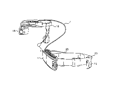
In figure 6, fiber optics bundle 7 connects the colllpul~r housing 1 with a lightweight
eyeglass head mounted display ~D 22. The H~ 22 contains an e~,holle 24 cormectedto the modified eyeglasses 25. Audio or voice activation means 17 is shown but other
lO activation means mentioned earlier in this disclosure may be used with the system of this
invention. In this embo~lim~nt of the invention, components generally found in HMD 16 (see
figure 4) can have all or a portion of the coml)onelll~ co~ ;,-ed in the CG~ uh~l housing 1
and fiber optics bundle 7 conveys all ayplolJliate signal or signals to eyeglass HMD 22.
Fiber optics bundle 7 is ~tt~ch~d to eyeglass HMD 22 and reflective area 23 reflects image
l 5 being transferred via fiber optic bundle. Reflective area 23 can also be located in left or right
eyeglass lens.
The l~lc~ d and o~,Lilllulllly ~ f~,~lc;d embodiments of the present invention have
been described herein and shown in the accolll~allying drawing to illustrate the underlying
principles of the invention but it is to be understood that llulll~ruus motlific~tions and
ramifications may be made without departing from the spirit and scope of this invention.