Language selection

Search

Patent 2219158 Summary

Third-party information liability

Some of the information on this Web page has been provided by external sources. The Government of Canada is not responsible for the accuracy, reliability or currency of the information supplied by external sources. Users wishing to rely upon this information should consult directly with the source of the information. Content provided by external sources is not subject to official languages, privacy and accessibility requirements.

Claims and Abstract availability

Any discrepancies in the text and image of the Claims and Abstract are due to differing posting times. Text of the Claims and Abstract are posted:

  • At the time the application is open to public inspection;
  • At the time of issue of the patent (grant).
(12) Patent: (11) CA 2219158
(54) English Title: A SPOKE-NIPPLE AND A METHOD FOR ITS MANUFACTURE
(54) French Title: ECROU DE RAYON ET METHODE DE FABRICATION
Status: Expired and beyond the Period of Reversal
Bibliographic Data
(51) International Patent Classification (IPC):
  • F16B 37/00 (2006.01)
  • B60B 1/00 (2006.01)
  • B60B 1/04 (2006.01)
(72) Inventors :
  • CAPPELLOTTO, GUIDO (Italy)
(73) Owners :
  • ALPINA RAGGI S.P.A.
(71) Applicants :
  • ALPINA RAGGI S.P.A. (Italy)
(74) Agent: OYEN WIGGS GREEN & MUTALA LLP
(74) Associate agent:
(45) Issued: 2008-02-26
(22) Filed Date: 1997-10-22
(41) Open to Public Inspection: 1998-04-24
Examination requested: 2002-09-06
Availability of licence: N/A
Dedicated to the Public: N/A
(25) Language of filing: English

Patent Cooperation Treaty (PCT): No

(30) Application Priority Data:
Application No. Country/Territory Date
PD96A000261 (Italy) 1996-10-24

Abstracts

English Abstract

A spoke nipple comprises a body of substantially undeformable material with a head and a shank which have an at least partially threaded axial hole for housing the thread of a spoke, and with a perforated insert of substantially deformable material fixed to the body with the holes in the body and in the insert arranged coaxially, the insert having an inside diameter such as to house the thread of the spoke with interference when it is screwed into the axial hole in the nipple body.


French Abstract

Écrou de rayon comprenant un corps d'un matériau essentiellement indéformable, avec une tête et une tige qui comporte au moins un trou axial partiellement fileté pour loger le filet d'un rayon, et avec une pièce rapportée perforée d'un matériau essentiellement déformable fixée au corps, les trous dans le corps et la pièce rapportée étant coaxiaux; la pièce rapportée comporte un diamètre interne de façon à loger le filet du rayon par interférence lorsqu'il est vissé dans le trou axial dans le corps de l'écrou.

Claims

Note: Claims are shown in the official language in which they were submitted.

WHAT IS CLAIMED IS:
1. A spoke nipple comprising:
a body of substantially undeformable material with a head and a shank
which have an axial hole for housing the thread of a spoke; and
a perforated insert of substantially deformable material, said insert having
an insert hole and being fixed to the body such that said insert hole and said
axial
hole are arranged coaxially, said insert hole being thread-engaged with
interference by the threads of the spoke when said spoke is coupled to said
nipple;
wherein the axial hole in the body is at least in part threaded to receive in
thread-engagement the threads of said spoke to retain axially said nipple to
said
spoke, and wherein the thread-engagement of the spoke and the insert is
provided
to prevent accidental rotation and loosening of the spoke relatively to the
nipple
body.
2. A nipple according to Claim 1, in which the insert is housed in a seat
formed at the free end of the head.
3. A nipple according to Claim 2, in which the insert is recessed in the head.
4. A nipple according to any one of Claims 1 to 3, in which the seat is
defined between a shoulder and a projecting lip of the head, the insert being
6

restrained in the seat between the shoulder and the lip.
5. A nipple according to any one of Claims 1 to 4, in which the material of
the body is metallic.
6. A nipple according to any one of Claims 1 to 5, in which the insert is made
of plastics material.
7. A nipple according to any one of Claims 1 to 6, in which the insert has an
approximately spherical shape.
8. A method of manufacturing a spoke nipple comprising a body of
substantially undeformable material with a head and a shank which have an
axial
hole for housing the thread of a spoke, the method comprising the steps of:
providing an insert of substantially deformable material
providing a hole in the insert and fixing it to the body with the holes in the
insert and in the body arranged coaxially, the hole in the insert having an
inside
diameter such as to house the thread of the spoke with interference when it is
screwed into the hole in the body;
nesting said insert in the axial hole of the body so that a portion of said
axial hole in the body remains free from said insert; and
threading at least in part said free portion of the axial hole in the body to
7

receive in thread-engagement the threads of said spoke so as to retain axially
said
nipple to said spoke.
9. A method according to Claim 8, in which the holes in the body and in the
insert are formed simultaneously whilst the insert is restrained in a
corresponding
seat in the body.
8

Description

Note: Descriptions are shown in the official language in which they were submitted.


CA 02219158 1997-10-22
A spoke-nipple and a method for its manuracture
DESCRIPTION
The subject of the present invention is a spoke nipple
comprising a bod_v of substantially undeformable material
with a head and a shank which have an at least partiallv
threaded axial hole for housing the thread of a spoke. The
invention also relates to a method of manufacturing the
nipple.
Nipples having the characteristics indicated above are
used widely in the construction of spoked wheels, for
restraining the threaded end of the spoke on the rim of the
wheel.
In this field, it has been noticed in the past in
wheels with conventional spokes and, more recently, with
some types of spokes, particularly so-called straight spokes
which do not have a bend at the axially opposite end to the
thread for the attachment of the nipple, that the nipple may
slowly unscrew under load, in use. This leads to inadequate
functioning of the wheel owing to the gradual loosening of
the nipples, and consequently to a dangerous weakening of
the wheel as a whole.
To prevent this problem, some wheel assemblers use
special adhesives or glues which are spread on the threaded
portions of the spoke and/or of the nipple before it is
tightened. However, the effect of these glues is difficult
to control - in some cases they may completely block the
nipple, preventing its subsequent removal - and, in any
case, the effect is cancelled out if the wheel is subjected
to successive adjustments of the tension in the spokes
involving the release of one or more nipples.
1

CA 02219158 1997-10-22
The technical problem upon which the invention is based
is that of providing a spoke nipple which overcomes the
problems complained of with reference to the prior art
mentioned.
This problem is solved by the invention by means of a
nipple having the aforementioned features and characterized
in that it comprises a perforated insert of substantially
deformable material which is fixed to the body with the
holes in the insert and in the body arranged coaxially, the
hole in the insert having an inside diameter such as to
house the thread of the spoke with interference when it is
screwed into the hole in the body.
The characteristics and advantages of the invention
will become clearer from the following detailed description
of a preferred embodiment thereof, shown by way of non-
limiting example in the appended drawings, in which:
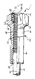
Figure 1 shows a nipple formed according to the present
invention, half as a front elevational view and half in
longitudinal section,
Figures 2 and 3 are longitudinal sections of two
successive stages of the manufacture of the nipple of Figure
1,
Figures 4 and 5 are a section of the nipple of the
preceding drawings taken on the line IV-IV of Figure 3, and
a corresponding section of a variant thereof, respectively,
Figure 6 is a longituciinal section of a variant of the
nipple of the invention,
Figures 7 to 9 are longitudinal sections of the nipple
of Figure 6 in the various stages of manufacture.
With reference to Figure 1, a nipple 1 formed in
accordance with the invention comprises a metal body 2 which
2

CA 02219158 1997-10-22
has an axis X and an axial hole 3, and in which a shank 4
and a head 5 with a polygonal key portion 7, possibly with
a notch 8 for a screwdriver, are identified. A further key
portion 6 formed on the outside of the shank 4 on an end
portion thereof is also polygonal, generally square, in plan
(figure 4) but, in a possible variant of the invention, may
have the configuration of Figure 5, that is a grooved
profile 6a.
At the opposite end to the head 5, the axial hole 3 has
an enlarged mouth 10 followed by a threaded portion 11, the
hole 3 terminating, at the free end of the head 5, in a
greatly enlarged seat 12. In this seat, a wall 13 with a
cylindrical surface of axis X, a shoulder 14 close to the
threaded portion 11, and a lip 15 at the axially opposite
end can be seen. An insert 16 of plastics material or
another material which is relatively deformable, at least
relative to the low deformability of the metal body 2, is
force-fitted in the seat 12. The insert 16 has an axial
hole 17 in which a threaded portion 18 of a spoke 19 screwed
into the nipple 1 can engage by screwing, forming its own
thread but maintaining an interference fit with the insert
16.
In the embodiment of Figures 1 to 3, the seat 12 has a
cylindrical surface and the insert 16 is in the shape of a
tubular sleeve which has a chamfered end and is fitted in
the seat 12 after the threading of the hole 3, being held
therein by the upsetting of the lip 15 from the position of
Figure 2 to that of Figure 3.
In a variant of the invention, generally indicated 20
in Figure 6, the seat 21 is generally spherical and the
external shape of the insert 22 is also spherical. The
3

CA 02219158 1997-10-22
insert is fitted in the seat 21 before the hole 3 is
machined so that the hole is formed simultaneously in the
body 2 and in the insert 22, thus achieving a better
guarantee that the holes are coaxial. This aspect is
particularly important on account of the very small
dimensions of the nipple of the invention, owing to which
serious problems may arise in the coaxial arrangement of the
holes during separate machining of the body 2, particularly
the seat 21, and of the insert 22.
With reference specifically to Figures 7 to 11,
however, it is envisaged that the metal body 2 of the nipple
20 will be produced from a blank 25 (Figure 7) produced, for
example, by upsetting or moulding, and that the hole 3,
complete with the thread 11 (Figure 8) as well as the seat
21, will then be formed therein, although without the
upsetting of the lip 15 (Figure 9). The insert 22 will then
be fitted, without a hole (Figure 10), and the lip 15 will
be upset so as to lock it in the seat 21. It will be noted
that the spherical shape of the insert facilitates its
positioning in the seat 21 and prevents it from being
damaged during the upsetting of the lip 15 by virtue of the
optimal distribution of the forces achieved precisely by
virtue of the spherical shape. The insert will then be
perforated with a tool from the head end 5 and machined to
the final shape of Figure 11.
It will also be noted that the axial extent (SI) of the
insert is quite large relative to the axial extent (SF) of
the threaded portion of the nipple. Preferred values ofthis
ratio (SI/SF) are between 0.2 and 0.4.
The invention thus conceived achieves the results set
as well as many advantages in comparison with conventional
4

CA 02219158 1997-10-22
nipples. In particular, it achieves effective clamping
which is not dependent upon actions of the assembler of the
wheel. The clamping is repeatable, even if the nipple is
subsequently rotated relative to the spoke during the
adjustment of the wheel and the result offers a lasting
guarantee of safety of the wheel. Moreover, the use of
approximately spherical inserts facilitates the location and
clamping of the nipple in the body, particularly with small
nipples. Finally, the solution of the second embodiment,
that is, the simultaneous machining of the hole in the body
of the nipple and in the insert solves any problems with the
coaxial arrangement of the holes resulting from the small
dimensions of the respective details.

Representative Drawing
A single figure which represents the drawing illustrating the invention.
Administrative Status

2024-08-01:As part of the Next Generation Patents (NGP) transition, the Canadian Patents Database (CPD) now contains a more detailed Event History, which replicates the Event Log of our new back-office solution.

Please note that "Inactive:" events refers to events no longer in use in our new back-office solution.

For a clearer understanding of the status of the application/patent presented on this page, the site Disclaimer , as well as the definitions for Patent , Event History , Maintenance Fee  and Payment History  should be consulted.

Event History

Description Date
Time Limit for Reversal Expired 2016-10-24
Letter Sent 2015-10-22
Grant by Issuance 2008-02-26
Inactive: Cover page published 2008-02-25
Inactive: Final fee received 2007-12-10
Pre-grant 2007-12-10
Notice of Allowance is Issued 2007-07-03
Letter Sent 2007-07-03
Notice of Allowance is Issued 2007-07-03
Inactive: Approved for allowance (AFA) 2007-05-30
Amendment Received - Voluntary Amendment 2006-08-25
Inactive: IPC from MCD 2006-03-12
Inactive: S.30(2) Rules - Examiner requisition 2006-02-28
Inactive: S.29 Rules - Examiner requisition 2006-02-28
Amendment Received - Voluntary Amendment 2003-06-11
Letter Sent 2002-11-13
Letter Sent 2002-10-11
Request for Examination Requirements Determined Compliant 2002-09-06
All Requirements for Examination Determined Compliant 2002-09-06
Request for Examination Received 2002-09-06
Inactive: Office letter 2001-10-26
Application Published (Open to Public Inspection) 1998-04-24
Classification Modified 1998-02-18
Inactive: First IPC assigned 1998-02-18
Inactive: IPC assigned 1998-02-18
Inactive: IPC assigned 1998-02-13
Inactive: Filing certificate - No RFE (English) 1998-01-21
Filing Requirements Determined Compliant 1998-01-21
Letter Sent 1998-01-21
Application Received - Regular National 1998-01-20

Abandonment History

There is no abandonment history.

Maintenance Fee

The last payment was received on 2007-10-10

Note : If the full payment has not been received on or before the date indicated, a further fee may be required which may be one of the following

  • the reinstatement fee;
  • the late payment fee; or
  • additional fee to reverse deemed expiry.

Please refer to the CIPO Patent Fees web page to see all current fee amounts.

Owners on Record

Note: Records showing the ownership history in alphabetical order.

Current Owners on Record
ALPINA RAGGI S.P.A.
Past Owners on Record
GUIDO CAPPELLOTTO
Past Owners that do not appear in the "Owners on Record" listing will appear in other documentation within the application.
Documents

To view selected files, please enter reCAPTCHA code :


To view images, click a link in the Document Description column. To download the documents, select one or more checkboxes in the first column and then click the "Download Selected in PDF format (Zip Archive)" or the "Download Selected as Single PDF" button.

List of published and non-published patent-specific documents on the CPD .

If you have any difficulty accessing content, you can call the Client Service Centre at 1-866-997-1936 or send them an e-mail at CIPO Client Service Centre.


Document
Description 
Date
(yyyy-mm-dd) 
Number of pages   Size of Image (KB) 
Representative drawing 1998-05-11 1 7
Cover Page 1998-05-11 1 39
Abstract 1997-10-22 1 14
Description 1997-10-22 5 188
Claims 1997-10-22 2 58
Drawings 1997-10-22 2 53
Claims 2006-08-25 3 71
Representative drawing 2008-02-04 1 7
Cover Page 2008-02-04 1 33
Courtesy - Certificate of registration (related document(s)) 1998-01-21 1 118
Filing Certificate (English) 1998-01-21 1 165
Reminder of maintenance fee due 1999-06-23 1 112
Reminder - Request for Examination 2002-06-26 1 128
Acknowledgement of Request for Examination 2002-10-11 1 176
Commissioner's Notice - Application Found Allowable 2007-07-03 1 165
Maintenance Fee Notice 2015-12-03 1 170
Correspondence 2001-10-26 6 238
Correspondence 2002-11-13 2 18
Fees 2002-10-21 1 49
Fees 2003-10-14 1 30
Fees 2007-10-10 1 33
Correspondence 2007-12-10 1 33