Note: Descriptions are shown in the official language in which they were submitted.
CA 02219237 1997-10-27
WO 96/37644 PC'TlUS96/05080
UNDRAWN TOUGFI. DURABLY MELT-BONDABLE, MACRODENIER,
TFfERMOPLASTIC. MULTICOMPONENT FILAMENTS
This invention relates to melt-extruded, melt-bondable, thermoplastic
filaments or fibers, particularly multicomponent fibers, such as bicomponent
fibers
of the sheath-core type, precursor thermoplastic polymers therefor, and
articles of
such filaments or fibers, such as open, nonwoven webs useful in the form of
entry-
way floor matting or abrasive pads. In another aspect, this invention relates
to
methods of making said filaments or fibers and articles thereof. In a still
further
aspect, this invention relates to thermoplastic alternatives for polyvinyl
chloride).
Fibers based on synthetic organic polymers have revolutionized the textile
industry. One manufacturing method of fiber formation is melt spinning, in
which
synthetic polymer is heated above its melting point, the molten polymer is
forced
through a spinneret (a die with many small orifices), and the jet of molten
polymer
emerging from each orifice is guided to a cooling zone where the polymer
solidifies.
In most instances the filaments formed by melt spinning are not suitable
textile
fibers until they have been subjected to one or more successive drawing
operations.
Drawing is the hot or cold stretching and attenuation of fiber filaments to
achieve an
irreversible extension and to develop a fine fiber structure. Typical textile
fibers
' 20 have linear densities in the range of 3 to 15 denier. Fibers in the 3 to
6 denier range
are generally used in nonwoven materials as well as in woven and knitted
fabrics for
use in apparel. Coarser fibers are generally used in carpets, upholstery, and
certain
industrial textiles. A recent development in fiber technology is the category
of
microfibers with linear densities < 0.11 tex ( 1 denier). Bicomponent fibers,
where
two different polymers are extruded simultaneously in either side-by-side or
skin/core configurations, are also an important category of fibers. Kirk-
Othmer
Encyclopedia of Chemical 'technology, Fourth Ed., John Wiley & Sons, N.Y.,
Vol.
' 10, 1993, "Fibers," pp. 541, 542, 552.
A type of bicomponent fiber is the bicomponent binder fiber, the historical
paper by D. Morgan which appears in INDA Journal of Nonwoven Research, Vol.
4(4), Fall 1992, pp. 22-26. This review article says it is worth noting that
the
majority of bicomponent fibers so far made have been side-by-side acrylics
used in
-1-
SUSSTtTUTE SHEET (RULE 28)
CA 02219237 1997-10-27
WO 96/37644 PGT/US96/05080
knitwear garments to provide bulk. Table 1 of this review article lists
suppliers of
various bicomponent fibers, which are of relatively low denier, ranging from
about 1
to up to 20.
U.S. Pat. Nos. 4,839,439 (McAvoy etet al.) and 5,030,496 (McGurran)
describe nonwoven articles prepared by blending melt bondable, bicomponent
sheath/core, polyester, staple fibers having a denier of six and larger, for
example
15, with synthetic, organic, staple fibers, forming a nonwoven web from the
blend,
heating the web to cause the melt bondable staple fibers to initially bond, or
prebond, the web, coating the web with a binder resin, and drying and heating
the
coated web.
U.S. Pat. No. 5,082,720 (Hayes) discusses prior art relating to nonwoven
webs of bicomponent melt-bondable fibers. The invention of the Hayes patent is
directed to drawn or oriented, melt-bondable, bicomponent filaments or fibers
of I
to 200 denier formed by the co-spinning of at least two distinctive polymer
components, e.g., in a sheath-core or side-by- side configuration, immediately
cooling the filaments after they are formed, and then drawing the filaments.
The
first component is preferably at least partially crystalline polymer and can
be
polyester, e.g., polyethylene terephthalate; polyphenylenesulfide; polyamide,
e.g.,
nylon; polyimide; polyetherimide; and polyolefin, e.g., polypropylene. The
second
component comprises a blend of certain amounts of at least one polymer that is
at
least partially crystalline and at least one amorphous polymer, where the
blend has a
melting point of at least I30°C and at least 30°C below the
melting point of the first
component. Materials suitable for use as the second component include
polyesters,
polyolefins, and polyamides. The first component can be the core and the
second
component can be the sheath of the bicomponent fiber.
Filaments of poly(vinylchloride) ("PVC," or simply "vinyl"), a synthetic
thermoplastic polymer, are used to make open or porous, nonwoven, three-
dimensional, fibrous mats or matting. The mats are used for covering any of a
variety of floors or walking surfaces, such as those of office building,
factory, and
residential entry-ways or foyers and hallways, areas around swimming pools,
and
machine operator stations, to remove and trap dirt and water from the bottom
(soles and heels) of shoes, protect floors and carpets, reduce floor
maintenance, and
-2
SUBSTITUTE SHEET (RULE 26)
CA 02219237 1997-10-27
WO 96/37644 PCT/US96/05080
provide safety and comfort. Generally the mats are open or porous webs of
interengaged or intertwined, usually looped, sinuous, or coifed, coarse or
large-
diameter fibers (or filaments); such fibers are typically melt-extruded from
plasticized PVC into single-component fibers which are aggregated and bonded
(usually with an applied binder coating or adhesive). An example of
commercially-
available matting product is NomadTM matting constructed of interengaged loops
of
vinyl filaments that are bonded together and may be supported on and adhered
to a
backing -- see product bulletins 70-0704-2684-4 and 70-0704-2694-8 of the 3M
Company, St. Paul, Minnesota, U.S.A.
Relatively early patents describing matting made from various thermo-
plastics including PVC are U.S. Pat. Nos. 3,837,988 (Hennen et al.), 3,686,049
(Manner et al. , 4,351,683 (Kusilek), and 4,634,485 (Welygan et al.). Common
aspects of the method described in these patents, briefly stated, comprises
extruding
continuous filaments of thermoplastic polymer downward toward and into a water
quench bath where a web of interengaged, integrated, or intermingled and spot-
bonded filaments is formed. The web can be subsequently treated with bonding
agent or resin to improve bonding, strength, or integration. Typically, in the
absence of a bonding agent or resin applied and cured subsequent to the web-
forming step, the filaments of the web exhibit a tensile strength much greater
than
that of the spot-bond itself. That is, as a result of tensile force applied to
the web
after spot welding but before application of a subsequent bonding treatment,
the
fibers of the web will separate at the sites of interfilament bonding more
frequently
than the fibers will break.
Recently polyvinyl chloride) has been said to be environmentally
undesirable because its combustion products include toxic or hazardous
hydrogen
chloride fumes. It has been reported that the existing use of PVC in Sweden
should
be phased out by the year 2000 -- see European Chemical News, 4 July 1994, p.
23.
One Swedish commercial enterprise stated it plans to stop making PVC-based
elastic flooring and launch a new, PVC-free flooring -- see Plastic Week,
August 9,
1993. Thus attention is being directed to alternatives for PVC.
Bicomponent fibers and multicomponent fibers are described in Kirk
Othmer Encyclopedia of Chemical Technology. Third Ed., Supplement Vol., 1984,
-3-
SUBSTITUTE SHEET (RULE 2fi)
CA 02219237 2005-03-29
60557-5644
pp. 372-392, and Encyclopedia of Poivmer Science and Technology, 3ohn Wiley &
Sons, N.Y.,VoI. 6, 1986,~pp. 830, 831. Patents describing certain
rnulticomponent
or bicomponent fibers include U.S. Pat. Nos. 3,589,956 (Kranz e~, 3,707,341
(Fontijn stet al.), 4,189,338 (Ejima g~, 4,211,819 (Kunimune), 4,234,655
S (Kunimune gt~, 4,269,888 (Ejima g~l,~, 4,406,850 (Hills), 4,469,540
(Jurukawa
4,500,384 (Tomioka et 1 , 4,552,603 (Harris et , 5,082,720 (Hayes),
5,336,552 (Strack stet at.l. The process of manufacture of multicomponent
fibers
and a general discussion of the method of extrusion of these fibers are also
described in Kirk-Othmer, Third Ed., loc. cit. Some patents describing
spinneret
assemblies for extruding bicomponent fibers of the sheath-core type are U.S.
Pat.
Nos. 4,052,146 (Sternberg), 4,251,200 (Parkin), 4,406,850 (Ills), and PCT
International Appln. published as WO 89/02938 (Hills Res. & Devel. Inc.).
Some other patent filings, viz., U.S. Pat. Nos. 3,687,?59 (Werner tg~l and
3,591,004 (Werner et al.), though they do not describe PVC matting, describe
1 S mattings of filaments of substantially amorphous polymer, such as
polycaprolactam,
which are formed by melt spinning into a liquid quench bath in such a manner
that
the filaments lie in the form of overlapping loops randomly bonded at their
points of
contact as they solidify in the bath. These patents state that preferably the
filaments
are spun, looped, and bonded without any substantial tension being placed on
the
filaments, or that it is preferable to avoid any substantial tension capable
of
stretching the filaments as they are withdrawn through the cooling bath so
that the
amorphous character of the initial polymer is largely retained. Matting
articles
which are formed without spinning into a liquid quench bath and consisting
essentially of melt-spun filaments which are self bonded or fused at random
points
of intersection without using any bonding agent have been described in U.S.
Pat.
No. 4,252,590 (Rasen ~.
A series of patents issued to Yamanaka , viz., U.S. Pat. Nos.
4,859,516, 4,913,757, and 4,952,265, describe various mats consisting of
$lament
loop aggregations formed by extruding thermoplastic synthetic resin vertically
toward the surface of a cooling bath of water at a speed regulated by guide
rollers
disposed in the water (to which a surface active agent can be added), the
density of
-4-
CA 02219237 1997-10-27
R'O 96/37644 PCT/gTS96/05080
the aggregations of the resulting bonded or fused aggregations being regulated
in
certain manners.
This invention, in one aspect, provides undrawn, tough, durably melt-
bondable, thermoplastic, macrodenier, multicomponent filament comprising,
consisting, or consisting essentially of the following components:
(a) first plastic comprising synthetic organic plastic polymer, preferably
a thermoplastic, which can be semicrystalline, such as nylon 6; and
(b) second plastic comprising synthetic organic thermoplastic polymer,
such as ethylene-vinyl acetate copolymer or a blend of an ethylene-
vinyl acetate copolymer and an ethylene-methyl acrylate copolymer,
which melts upon heating at a temperature lower than the
temperature which melts component (a), e.g., at least 1 S°C lower,
preferably 30°C lower, and is generally amorphous or
semicrystalline;
said components (a) and (b) being, along the length of the filament,
elongated,
contiguous, coextensive in length, and, preferably, integral and inseparable
(e.g., in
boiling water), said component (b) defining all or at least part (e.g., 5 to
90%,
preferably 20-85%) of the material-air boundary or peripheral or external
surface of
the filament. The plastic of each of said components (a) and (b) can be a
single
plastic substance or a blend of a plurality of plastic substances and can
consist or
consist essentially of such plastic substances. Said components can further
comprise or have incorporated adjuvants or additives to enhance a property of
or
impart a property to the filament, such as stabilizers, processing aids,
fillers,
coloring pigments, crosslinking agents, foaming agents, and fire retardants.
The
filament can comprise a plurality, e.g., 2 to 5, of components (a) and/or of
components (b), a preferred multicomponent filament being a bicomponent
filament,
such as a sheath-core or side-by-side filament.
Another aspect of this invention provides a method of making the above-
described multicomponent filaments. Such method comprises continuous steps of
simultaneously (or conjointly) melt-extruding, preferably at the same speed,
molten
streams of thermoplastic polymers (some of which are novel blends of polymers)
as
precursors of components (a) and (b) via one or a plurality, e.g., 1 to 2500,
SUBSTITUTE SHEET (RULE 26)
CA 02219237 2005-03-29
60557-5644
preferably 500 to 1800, extruder die openings or orifices,
. in the form of a single or a plurality of discrete and
separate hot, tacky, molten, multicomponent filaments,
cooling them, for example, in a water quench bath, and
recovering the resulting non-tacky, solidified filaments,
for example, as a tow or web of such filaments.
In another aspect of this invention, a plurality
of the above-described solidified filaments are self-bonded
to one another by heating an aggregation thereof, e.g., in
the form of an open, nonwoven web of the filaments in a
coiled form, to or above the melting point of component (b)
in order to effect durable melt-bonding at filament surfaces
in contact with melted component (b), and thereby provide a
sufficiently bonded aggregation of the filaments, e.g., an
open, nonwoven web of durably melt-bonded, undrawn, tough,
macrodenier, multicomponent filaments. Such bonding can be
accomplished without requiring or using a coating or
otherwise applying to the filaments a binder resin, solvent,
or extra adhesive or mixing the filaments with so-called
binder fibers, though such materials may be used to
supplement the self-bonding of the filaments.
According to one aspect of the present invention,
there is provided a macrodenier multicomponent filament
comprising: (a) a first plastic component comprising
synthetic plastic polymer; and (b) second plastic component
comprising lower melting, synthetic thermoplastic polymer
having a melting point at least 15°C lower than the melting
point of said component (a), said components (a) and (b)
each having a flex-fatigue resistance greater than 200
cycles to break as measured according to ASTM D2176-63T,
-6-
CA 02219237 2005-03-29
60557-5644
and being, along the length of the filament, elongated,
- contiguous, and coextensive in length, said component (b)
defining all or at least part of the material-air boundary
of said filament, said filament being durably melt-bondable
in its undrawn state.
According to another aspect of the present
invention, there is provided undrawn, tough, durably melt-
bondable, thermoplastic, sheath-core bicomponent filaments
having a linear density of 500 to 20,000 denier per
filament, and comprising the following components: (a) a
central core comprising nylon; and (b) a sheath comprising a
blend of ethylene-vinyl acetate copolymer and ethylene-
methyl acrylate copolymer, said components (a) and (b) each
having a flex-fatigue resistance greater than 200 cycles to
break as measured according to ASTM D2176-63T.
According to still another aspect of the present
invention, there is provided a filamentary structure
comprising at least one central, regularly undulating or
spiral sheath-core filament surrounded and bonded to a
plurality of straight, parallel sheath-core filaments, said
central and straight filaments being as defined herein.
According to yet another aspect of the present
invention, there is provided matting comprising an open,
nonwoven web of a plurality or filaments as defined herein,
which are durably melt-bonded at points of intersection or
contact.
According to a further aspect of the present
invention, there is provided an abrasive article comprising
an open, nonwoven web of the filaments as defined herein,
surfaces of which are bonded to abrasive particulate.
-6a-
CA 02219237 2005-03-29
60557-5644
According to yet a further aspect of the present
invention, there is provided method of a making a
macrodenier multicomponent filament as defined herein, which
method comprises the continuous steps of simultaneously
melt-extruding a molten stream of first thermoplastic,
synthetic, organic polymer and a molten stream of second
thermoplastic, synthetic, organic polymer of lower melting
point to form a hot, tacky, molten, melt-bondable,
thermoplastic, macrodenier, multicomponent filament
comprising said components (a) and (b) which are derived,
respectively, from said first and second thermoplastics,
permitting said hot filament to cool and solidify, and
recovering the resulting solidified filament without any
substantial tension being placed thereon.
According to still a further aspect of the present
invention, there is provided a method of making a
macrodenier multicomponent filament comprising: (a) a first
plastic component comprising synthetic plastic polymer; and
(b) second plastic component comprising lower melting,
synthetic thermoplastic polymer having a melting point at
least 15°C lower than the melting point of said
component (a): said components (a) and (b) each having a
flex-fatigue resistance greater than 200 cycles to break as
measured according to ASTM D2176-63T, and being, along the
length of the filament, contiguous, and coextensive in
length, said component (b) defining at least in part the
material-air boundary of said filament, said filament being
durably melt-bondable in its undrawn state; which method
comprises the continuous steps of simultaneously melt-
extruding a plurality of molten streams of thermoplastic,
-6b-
CA 02219237 2005-03-29
60557-5644
synthetic, organic polymers as precursors of said
t components (a) and (b) from an extrusion die to form a
bundle of hot, tacky, closely spaced, discrete, continuous,
macrodenier, multicomponent filaments each of which
comprises said components (a) and (b), permitting said
filaments to cool and solidify, and recovering the resulting
solidified filaments without any substantial tension being
placed thereon.
The filaments of this invention, following their
melt-extrusion and cooling to a solidified form, are not
subsequently or additionally drawn, that is, stretched,
pulled, elongated, or attenuated. In contrast, textile
fibers, including bicomponent textile fibers, are commonly
drawn as much as, for example, 2 to 6 or even 10 times their
original length, usually to increase their strength or
tenacity.
The filament of this invention, as that term is
used herein, is an elongated or slender article which is
narrow or small in width, cross section, or diameter in
proportion to its length. Generally the filament can have a
width, diameter, or cross-section dimension of at least
0.2 mm, preferably at least 0.4 mm, which dimension
generally will be in the range of 0.5 to 25 mm, preferably
0.6 to 15 mm, such dimension (and shape of the cross
section) being preferably substantially or essentially
uniform along the length of the filament, e.g., uniformly
round. The surface of the filament is typically smooth and
continuous. Because the filament is larger in cross section
in comparison to bicomponent textile-size or textile-denier
filaments or "fine" fibers (which are generally considered
-6c-
CA 02219237 2005-03-29
60557-5644
to be 1 to 20 denier per fiber or "dpf"), the filament of
this invention is relatively coarse and can be characterized
(especially as compared to textile fibers) as being or
having a
-6d-
CA 02219237 1997-10-27
R'O 96/37644 PCT/US96/05080
macrodenier (and can even be characterized as being a macrofiiament).
Generally
the filament of this invention has a linear density greater than 200 dpf and
as much
as 10,000 dpf or more, e.g., up to 500,000 dpf, but preferably the filaments
of this
invention have linear densities in the range of 500 to 20,000 dpf.
The multicomponent filaments of this invention can be in the shape or form
of fibers, ribbons, tapes, strips, bands, and other narrow and long shapes.
Aggregations of the filaments, such as open, nonwoven webs, can be made up of
a
plurality of filaments with the same or different plastic compositions,
geometric
shapes, sizes and/or deniers. A particular form of such filaments is side-by-
side (or
side-side) bicomponent filaments or, preferably, sheath-core (or sheath/core)
bicomponent filaments, each comprising said components (a) and (b) with one or
more (e.g., 1 to 9) interfaces between the components and with the material-
air
boundary of the filament defined at least in part by an external surface of
component
(b). In a typical sheath-core filament, the sheath, component (b), provides a
matrix
(with a continuous external surface, the filament's material-air boundary) for
one or
more components (a) in the form of cores. The filaments can be solid, hollow,
or
porous and straight or helical, spiral, looped, coiled, sinuous, undulating,
or
convoluted. They can be circular or round in cross section or non-circular or
odd in
cross section, e.g., lobal, elliptical, rectangular, and triangular. They can
be
continuous in length, that is, of indefinite length, or, by cutting them in
that form,
they can be made in a short, discontinuous, or staple form of definite length.
The
components (a) and (b) can be solid or noncellular, or one or both components
can
be cellular or foamed with open and/or closed cells. Both of the components
(a)
and (b) can have the same form or shape or one of them can have one form or
shape
and the other component can have a different form or shape.
In characterizing the multicomponent filament of this invention as durably
melt-bondable, this means that a plurality or aggregation of such filaments,
such as
an open, non-woven web, can be bonded together at their points of contact or
intersection to form an interfilament-bonded structure by heating the
filaments
sufficiently to or above the melting point of their component (b) in order to
melt
component (b) without melting their component (a), and then cooling the
filaments
to solidify component (b), thereby causing the filaments to become bonded, to
one
SUBSTITUTE SHEET (RUi.E 2s)
CA 02219237 1997-10-27
w0 96/37644 PGT/US96l05080
another by a bond of component (b) at each of their contiguous material-air
boundaries, points of contact, or intersections. Such melt-bonding of the
filaments
is a self bonding in that it is effected without using or requiring the
application of an
external bonding agent, or solvent, or adhesive coating applied to the
filaments or
mixing so-called binder fiber therewith. This self bonding feature is thus an
environmental or cost advantage of the filaments of this invention vis-a-vis
those
known filaments or fibers that use or require such agent, solvent, coating, or
binder
fiber for bonding. This self bonding may additionally be characterized and
differentiated from spot- or tack-bonding, spot welding, or removably-welding
by
the strength of the bond formed. The melt-bond achieved by the filaments of
this
invention is a durable bond in that it is su~ciently strong or fracture
resistant that
interfilament melt-bond strength generally is at least as great as that of the
strength
of the filament itself, and generally the melt bond strength exceeds 1.4 MPa,
and
preferably is at least 4.8 MPa (ca 700 psi), based on the cross-section area
of the
filament before breaking stress is applied thereto. In a tack-bonded
structure, such
as that of an open, nonwoven web of coiled filaments, tack-bonded filaments
can be
relatively easily separated from the structure, e.g., by a pulling stress of
less than
0.02 MPa (ca 3 psi), based on the cross-section area of the filaments before
breaking stress is applied thereto, without distorting or breaking the
filaments
themselves. The fact that melt-bonded filaments of this invention themselves
break,
rather than their melt-bonds, attests to the durably melt-bondable character
of the
filaments (as well as to the durable melt-bonded character of a melt-bonded
aggregration of the filaments, such as an open nonwoven web). Furthermore, the
multicomponent nature of the filaments provides an unexpected advantage by
allowing component (a) thereof to provide a structural role in supporting the
shape
of the web of such filaments in either a post-formation melt-bonding step.
Because the filaments of this invention are self or melt-bondable, webs
formed from the melt-bonded filaments of this invention are durable without
requiring the application of binding agent, or adhesive coating, or solvent
and can
be used for article fabrication once the webs are melt-bonded. Contrariwise,
many
nonwoven webs made in whole or part from so-called binder fiber, which are
y typically textiie-size fibers, e.g., 3 to 15 dpf, are often additionally
bonded,
_g
SUBSTITUTE SHEET (RULE 26)
CA 02219237 2005-03-29
60557-5644
strengthened, or reinforced with binder resins that are roll- or spray-coated
on the
thermally-bonded web, especially when durability and toughness are needed.
The multicomponent filaments of this invention may be fabricated into
filamentary articles or structures or three-dimensional aggregations
comprising a
plurality of the filaments, which can be in either continuous or staple form.
For
example, said aggregations may be in the form of open, permeable or porous,
lofty
webs or balls of interengaged, intertwined, interlocked, or entangled
filaments or
twisted, woven, or braided filaments that can be generally straight or
helical, spiral,
looped, coiled, curly, sinuous or otherwise convoluted filaments which can
extend
from one end of the web to the other end. 'The contiguous material-air
boundaries
of the filaments can be melt-bonded at their points of intersection or contact
to form.
a water permeable, lofty or low bulk density, unitary, monolithic, coherent or
dimensionally-stable, three-dimensional filamentary stnreture or mass, such as
an
open, nonwoven web, minimal, or any, melted thermoplastic filling up the
interfilament gaps or interstitial spaces of the structure. Webs can be cut to
desired
sizes and shapes, for example, in lengths and widths useful, for example, as
floor
covering or door mats for building entrances and other walkway surfaces. If
desired, the web can be first melt-bonded on one side to suitable backing,
such as a
thermoplastic sheeting, prior to cutting into mats. Such masses, aggregations,
or
structures, when used as matting, provide resilient cushioning in the form of
lofty,
open, low bulk density, pliable mats or pads to cover floors or walking
surfaces to
protect the same from damage by dirt, liquid, or traffic wear, to provide
safety and
comfort to those people who walk or stand thereon, and to improve the
aesthetic
appearance of such substrates. Such mats can be stood or walked upon by people
over a very long time with comfort and safety and without losing their
durability.
The mats are preferably of such low bulk density or high void volume that, in
holding them up to a light source, light can be seen therethrough and dirt or
water
tracked thereon readily falls or penetrates therethrough. Generally, such mats
can
be used where PVC matting has been or can be used and as an alternative
thereto,
and, specifically, for those applications described in the above-cited 3M
Company
bulletins. The filamentary mass or web of this invention can also be used as a
spacer or cushioning web, a
-9-
CA 02219237 2005-03-29
60557-5644
filter web, as the substrate of scouring pads, erosion-control or civil
engineering
matting for retaining soil on embankments, dikes, and slopes and the like to
protect
them from erosion, as a substrate or carrier for abrasive particles and the
like, and
as a reinforcement for plastic matrices.
The multicomponent filaments of this invention can be fabricated with
indeterminate length, that is, in truly continuous form and, if desired, made
as long
in length as the supply of melt precursor or feed thereof lasts and having a
length
dependent only on the limitations of the fabricating equipment. Webs formed
from
these continuous filaments can be readily cut to desired dimensions, for
example,
after they are intertwined or intermeshed as looped or coiled, bonded
filaments in
the form of an open, nonwoven web or matting. Alternatively, these continuous
filaments can be cut into staple length fibers, for example, 2.5 - 10 cm in
length, and
such short lengths can used, for example, in a bonded aggregation as a
substrate for
abrasive cleaning and polishing pads in applications like those whose
fabrication is
described in said U.S. Pat. No. 5,030,496 and U.S. Pat. No. 2,958,593 (Hoover
e~
~L).
Preferably the filaments of this invention are melt-extruded as a bundle or
group of free falling, closely spaced, generally parallel, discrete,
continuous,
multicomponent filaments of hot, tacky, deformable, viscous polymer melts, for
example, as sheath~core bicomponent fibers, the hot filaments then being
quickly
cooled, or quenched, to a non-tacky or non-adhesive solid state. The hot
filaments
can be so-cooled or quenched to form a tow of non-tacky, essentially solid,
discrete
continuous filaments by contact with a cooling means or medium, such as a
liquid
quench bath, e.g., a body of water. The tow can then be advanced or conveyed
through the bath and withdrawn therefrom. The tow may then be further cooled,
if
desired. The tow can be used to fabricate nonwoven pads, such as those whose
fabrication is described in U.S. Pat. No. 5,025,591 (Heyer a al , used for
scouring
pots and pans, etc., or the tow can be cut into staple lengths which can be
used to
make abrasive pads, such as those whose fabrication is described in
U.S. Pat. No. 2,958,593 (Hoover et al.). If.the speed at which the
-10-
CA 02219237 2005-03-29
60557-5644
tow is withdrawn from the quench bath, i.e., the take-away speed, is equal to
or
greater than the speed of the hot filaments entering the quench bath, the tow
will
comprise essentially straight, non-coiled, non-convoluted, discrete filaments.
A tow comprised of helically shaped, coiled, or convoluted, discrete,
continuous, multicomponent filaments, one such filament being shown in Figure
4,
can be formed in the above-described fashion if the tow is conveyed through
the
quench bath at a take-away speed which is less than the speed of the filaments
entering the quench bath so as to permit the falling, molten, still defonmable
filaments to coil into an essentially helical shape adjacent the surface of
the quench
bath. The free-falling molten filaments preferably are sufficiently spaced-
apart to
prevent individual filaments from interfering with the coiling action of
adjacent
filaments. The use of a surfactant (for example, as described in said U.S.
Pat. No.
3,837,988) in the quench bath may be desirable to aid coil formation.
A web of coiled, muiticomponent filaments can be formed by permitting the
bundle of melt-extruded, free-falling filaments to (i) deform, coil, wind, or
oscillate
in a sinuous manner, (ii) interengage, intertwine, or aggregate in a desired
ordered
or random pattern to a desired web weight, (iii) tack- or spot-bond upon
contact
with each other, and (iv) immediately thereafter cool to a non-tacky, solid
state.
The free-falling molten filaments in the bundle are sufficiently spaced-apart
to allow
intermingling of the coiling and overlapping filaments. The take-away speed of
the
web preferably is sufficiently slow relative to the speed of the filaments
entering the
quench bath so as to allow the falling, coiling filaments to aggregate
adjacent the
surface of the quench bath as described in said U.S. Pat. No. 4,227,350 or
alternatively to aggregate on one or more contact surfaces adjacent the
surface of
the quench bath. The contact surfaces) may be in motion, as for example the
surface of a rotating cylindrical drum as described in said U.S. Pat. No.
4,331,683,
so as to collect the newly-forming web and help convey it into andlor through
the
quench bath. The substrate may alternatively be stationary, for example, a
plate as
described in said U.S. Pat. No. 3,691,004. The lightly-unified web thus
formed comprises overlapping or entangled loops or coils of filaments
and has sufficient structural integrity to allow the web to be conveyed,
-11-
CA 02219237 1997-10-27
WO 96/37644 PCT/I1S96/05080
transported, or otherwise handled. The web can be dried and stored if
necessary or
desired prior to the melt-bonding step. This melt-bonding step involves
heating the
lightly-unified web to cause melting of the lower-melting plastic of component
(b)
without deforming component (a), and then cooling the web to re-solidify
S component (b) in order to effect melt-bonding at points of intersection of
the
filaments to form an open, durably melt-bonded web.
In the above-described methods of fabricating multicomponent filaments of
this invention, unlike methods commonly used to manufacture single component
or
bicomponent fibers, such as textile fibers, the multicomponent filaments of
this
invention, as stated above, are undrawn. That is, the filaments of this
invention are
not mechanically, aerodynamically, or otherwise drawn, stretched, or pulled
after
they are quenched. The filaments, after having been quenched, are not
attenuated,
as for example, with a mechanical draw unit, air aspirator, air gun, or the
like, so as
to reduce their diameter, width, or cross-sectional area . After the hot
filaments are
cooled and solidified from their hot, tacky, molten state to their non-tacky,
solidified state, their diameters, widths, or cross-sectional areas and shape
remain
substantially or essentially the same in their finished state, that is, after
tow
collection or web formation and subsequent melt-bonding steps, as when first
cooled to the solid state. In other words, although the cooled and solidified
filaments can be thereafter aggregated, melt-bonded, conveyed, wound, or
otherwise handled or processed, such handling is done in a relatively relaxed
manner
without any substantial tension being placed on the solidified filaments.
Thus, once
solidified, the filaments of this invention are processed in an essentially
tension-less
manner, without substantial or significant attenuation, so that their denier
or
magnitude after processing to their finished form can be essentially the same
as that
upon first cooling the viscous filaments; consequently, the filaments are said
to be
undrawn.
Notwithstanding the multicomponent filaments of this invention are
undrawn, they are tough, that is, strong and flexible but not brittle or
fragile, and
the melt-bonded aggregations of such filaments are durable, that is, resistant
to
fatigue due to constant flexing, even though their bonding is achieved without
use
of an added or applied bonding or adhesive agent, such as coating with an
adhesive
-12
SUBSTITUTE SHEET (RULE 26)
CA 02219237 1997-10-27
WO 96/37644 PCTIUS96/05080
coating solution or mixing the filaments with added known binder fibers. In
contrast to drawn fibers, the cooled, solidified filaments of this invention
can be
readily stretched or drawn by grasping such a filament by two hands - one on
each
end of a segment (e.g., 10 cm long) - and pulling the segment between them,
for
example, to 2 or more times its initial length, thereby attenuating the
filament
diameter or cross-sectional area.
Because of the non-PVC thermoplastics which can be used to fabricate the
multicomponent filaments of this invention, environmental regulations which
restrict
the use of PVC will not necessarily be applicable to the fabrication, use, or
disposal
of the filaments of this invention. Another environmental advantage is that no
adhesive or volatile solvents are required to durably bond the filaments of
this
invention in the form of a unitary or monolithic structure, such filaments
being self
bondable, that is, melt-bonding at their contiguous material-air boundaries or
surfaces that are heated to melt the lower melting plastic of component (b) of
such
filaments and thermally bond the same at said boundaries or surfaces.
In the accompanying drawing, which depicts or illustrates some
embodiments and or features of this invention, and where like reference
numbers
designate like features or elements:
FIGURE lA is a schematic view in elevation and partial cross-section
showing one embodiment of apparatus that can be used to make a tow of straight
or
uncoiled, multicomponent filaments of this invention;
FIGURE IB is a schematic view in elevation and partial cross-section
showing another embodiment of apparatus that can be used according to this
invention to make coiled multicomponent filaments and an open, nonwoven web
thereof;
FIGURES 1C and 1D are schematic views in elevation and partial cross-
section showing embodiments of apparatus that can be used to make backed,
open,
nonwoven webs of coiled multicomponent filaments in accordance with this
invention;
FIGURE 2A is a schematic view in elevation and cross section of a portion
of an extruder die assembly useful in the apparatus of FIGURES 1 A - 1 D for
melt-
extruding sheath-core filaments of this invention;
-13
SIJBSTiTUTE SHEET (RULE 26)
CA 02219237 1997-10-27
WO 96/37644 PCTIUS96/05080
FIGURE 2B is a enlarged view in cross section of a portion of FIGURE 2A;
FIGURE 3 is a enlarged view of a portion of FIGURE 1B;
FIGURE 4 is a schematic isometric view of a single multicomponent
filament of this invention in its helical or coiled form;
FIGURE 5 is a schematic view in elevation and cross section of a portion of
another extruder die assembly useful in the apparatus of FIGURES lA - 1D;
FIGURE 6 is a partial cross-section and enlarged view of FIGURE 5 taken
along the line 6-6 thereof;
FIGURES 7 to 14 are schematic cross-sections of sheath-core
multicomponent filaments of this invention;
FIGURES 15 to 17 are schematic cross-sections of side-by-side
multicomponent filaments of this invention;
FIGURE 18 is a schematic cross-section of a bundle of unbonded, con-
tiguous, sheath-core filaments of this invention;
FIGURE 19 is a schematic cross-section showing the bonding of the
filaments of FIGURE 18;
FIGURE 20 is a schematic perspective view of portions of two unbonded
contiguous sheath-core filaments of this invention;
FIGURE 21 is a schematic perspective view showing the bonding of the
filaments of FIGURE 20 at their points of contact;
FIGURE 22 is a schematic view in perspective of a portion of a filamentary
matting of this invention;
FIGURE 23 is a schematic cross-section in elevation of a portion of a
filamentary matting of this invention which is bonded to a backing;
FIGURE 24 is a schematic isometric view of a portion of a matting of this
invention which is embossed on one side with a grid of channels;
FIGURE 25 is a schematic isometric view of a portion of bonded filaments
of this invention showing a broken filament and the residue of a broken melt-
bond;
and
FIGURE 26 is an isometric view of abrasive-coated filaments of this
invention.
-14-
SUBSTITUTE SHEET (RULE 26)
CA 02219237 2005-03-29
60557-5644
Referring now to the drawing, and initially to FIGURE 1 A, a first
thermoplastic polymer composition, to be used to form component (a) of
bicomponent filaments of this invention; is fed in pellet, crumb, or other
form into
the hopper l0a of a melt extruder 1 la, from which a stream of polymer melt
(e.g.,
at 100° to 400°C) is fed, optionally under pressure of a
metering pump 12a, into a
bicomponent extrusion die assembly 13. Similarly, a second thermoplastic
polymer
composition to be used to form component (b) of the bicomponent filaments is
fed
into the hopper l Ob of melt extruder 1 lb, from which a stream of polymer
melt is
fed, optionally under pressure of metering pump 12b, into the extrusion die
assembly 13. Examples of equipment for extruding bicomponent fibers are
described in Kirk-Othmer, Third Ed., Supp. Vol. sua~, p. 380-385. Examples of
extrusion die assemblies in the form of spinnerets are described in U.S. Pat.
Nos.
4,052,146 (Sternberg), 4,406,850 (Hills) and 4,251,200 (Parkin), PCT Appln. WO
89/02938 (Hills Research and Development Ine.), and Brit. Pat. 1,095,166
(Hudgell). Examples of extrusion dies are described by Michaeli, W. in
Extrusion
Dies. Designs and Computations, Hanser Pub., 1984, pp. 173-180.
The equipment therein can be modified in dimensions and configuration by
those skilled in the art for use in extruding the macrodenier, multicomponent
filaments of this invention in light of the description of it herein.
FIGS. 2A and 2B illustrate the bicomponent, filament, extrusion die
assembly 13 of F1G 1 A, such assembly being made of a number of machined metal
parts having various chambers, recesses, and passages for the flow of molten
thermoplastic and rigidly held together by various means (not shown in the
drawing), such as bolts. Assembly 13 comprises a dual-manifold of the slit
type
made up of mating blocks 14a and 14b each having a manifold passage disposed
therein and separated by a vertical plate 15. Manifold blocks 14a and 14b are
provided with opposing recesses at the lower ends in which is inserted a
mating pair
of prelip blocks 16a, 16b with flared, opposed iru~er surfaces separated by
the lower
portion of plate 15. Blocks 14a, 14b surmount a lower die holder 25 having a
recess to accommodate an inserted extrusion die pack 26 of the castellation
type
and comprising stacked plates, viz., top plate 18, center or distribution
plate 19, and
-15-
CA 02219237 1997-10-27
WO 96/37644 PGT/US96/05080
lower or orifice plate 20 from which issue hot, viscous, tacky, sheath-core
filaments
formed in the pack. Viscous core polymer composition, component (a) of the
filaments, is caused to flow from a feed passage 22a within manifold block 14a
to
distribution manifold passage 22b and thence into chamber 22c in top plate 18
that
functions as a local manifold from which the core polymer melt flows into an
array
ofvertical core flow passages 23 in plate 19. Viscous sheath polymer
composition,
component (b) of the filaments, is simultaneously caused to flow from a feed
passage 24a within dual manifold block 14b to a second polymer distribution
manifold passage 24b and thence into a second and separate chamber 24c in top
plate 18 that functions as a local manifold from which the sheath polymer melt
flows downwardly through a rectangular channel (shown by the broken line) in
center plate 19 to a horizontal recess or cavity 24d disposed between center
plate
19 and orifice plate 20. The latter has an array of circular vertical channels
27
axially aligned with core flow passages 23. Channels 27 communicate at their
upper ends with recess 24d and terminate at their lower ends with extruder
nozzles
having orifices 28. As shown clearly in FIG. 2B, the upper face of the orifice
plate
defining the bottom of recess 24d is machined with an array of raised,
circular
protuberances, buttons, or castellations 29, each surrounding the upper or
inlet end
of a channel 27 and defining a fine gap 30 between their upper surface and the
20 lower face of distribution plate 19 (or top of recess 24d) to ensure
uniform sheath
thickness. The sheath melt flows in fine gap 30 and enters channels 27 around
the
respective streams of core melt flowing from passages 23 into the cores of the
channels so that bicomponent sheath-core filaments issue from orifices 28, the
cross
section of such a filament being shown in FIG. 7.
Referring again to FIG. 1 A, the extruder die assembly 13 continuously
extrudes downwardly, in relatively quiescent air, a plurality or bundle 31 of
hot,
' viscous, tacky, closely-spaced, discrete, continuous, macrodenier,
multicomponent
filaments 32 which fall freely into a body or bath 33 of quench liquid, such
as water,
in an open-top tank 34. The surface 35 of the bath 33 is disposed a suitable
distance below the lower face of the extrusion die assembly 13 in order to
maintain
the discrete nature of falling filaments in the zone of cooling air above the
bath.
The bundle 31 upon entering the bath 33 is quickly cooled or quenched from the
-16-
SUBSTITUTE SHEET (RULE 26)
CA 02219237 2005-03-29
60557-5644
extrusion temperature, e.g., 100 to 400°C, down to about SO°C,
and solidified to a
non-tacky state. The discrete, quenched filaments 32 are continuously gathered
or
collected and are guided around turnaround roll 36 as a taw 30 which is
conveyed
by a pair of pinch rolls 37a and 37b out of the bath. The tow 30 may then be
wound on winder 38 to form a tow winding 40.
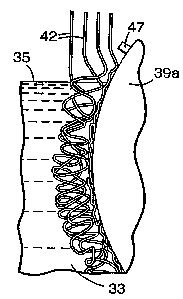
In a similar fashion, referring now to FIG. 1B, the extruder die assembly 13
(which, as in FIG. 1 A, is connected to extruders and optionally to metering
pumps,
not shown in FIG. 1B) extrudes downwardly a plurality or bundle 41 of hot,
viscous, tacky, closely-spaced, discrete, continuous, macrodenier,
multicomponent
filaments fibers 42 which fall freely in the quiescent ambient air into tank
34. The
bundle 41 can be aligned so that some of the hot, viscous filaments 42 are
permitted
to make glancing contact with the outer surface of a guide roll 39, optionally
provided with spaced-apart guide pins or pegs 47 (see FIG. 3), or some other
type
of guide, such as a stationery plate, to guide the hot, viscous filaments as
they move
toward the surface 35 of a body or bath 33 of quench liquid, such as water, in
tank
34, the surface of the liquid being disposed a suitable distance below the
lower face
of the extruder die assembly of 13 so as to achieve the desired diameter of
the
filaments as they enter the bath. The roll 39 can be set to cause glancing
contact
with the filaments 42, as described in said U.S. Pat. No. 4,351,683.
As the hot, viscous filaments 42 fall in the ambient air, they
begin to cool from the extruding temperature (which can
range, for example, from 100°C to 400°C). The guide roll 39 (as
well as optional
roll 48 and other rolls downstream) can be set to rotate at a predetermined
speed or
rate such that the rate of lineal movement of the filaments 4Z as they enter
the body
33 of quench liquid is slower than the rate of linear movement of the hot,
viscous
5laments upstream of the guide roll(s), gince the take-away speed is slower
than
the speed of the hot filaments entering the quench bath 33, and the filaments
42 are
still in a sufficiently viscous, deformable, or 'molten state, the filaments
accumulate
or aggregate themselves by coiling, undulating,, or oscillating and
interengaging just
above the surface 35 of the quench liquid 33 into which they enter and can
further
cool, e.g., to about 50°C, quickly enough so that their shape does not
deform, and
solidify or rigidify just below the surface 35. A degree of resistance is
imparted to
_17_
CA 02219237 1997-10-27
w0 96/37644 PGT/US96/05080
the flow or free fall of the hot, viscous filaments 42 above the surface 35 by
the
already quenched, aggregated filaments in the quench bath 33 below its
surface,
which causes the still deformable filaments entering the quench bath to coil,
oscillate, or undulate just above the surface of the bath. This motion
establishes
irregular or random periodic contact between the still-hot filaments,
resulting in
spot- or tack-bonding of contiguous surfaces of the filaments at their points
of
contact or intersection. Consequently, the filaments 42 assume a coiled,
looped,
sinuous, or undulating configuration and become interengaged as illustrated in
FIG.
3, one such filament being shown in FIG. 4. The filaments 42 upon entering the
quench liquid 33 and passing adjacent immersed guide roll 39 form an
integrated
web 43 of lightly spot- or tack-bonded, solidified filaments.
The web 43 can be conveyed and withdrawn from the tank 34 by means of
pinch rolls 44a and 44b and wound by roll 45 to form a winding 46 of the web.
In
this tack- or spot-bonded form, the filaments, though interengaged and lightly
bonded, generally can be individually and easily pulled by hand from the web
43 and
stretched to uncoil or straighten them in continuous form under such hand-
pulling
and without attenuation, showing that their tack-bonding is not durable. The
web
43 can be unwound from winding 46 and placed in an air-circulating oven or the
like to heat the web to an appropriate temperature for a sufficient time,
e.g., 120° to
300°C, preferably 140° to 250°C, for 1 to 5 minutes, and
then cooled to room
temperature (e.g., 20°C) to cause durable melt-bonding of the
contiguous surfaces
of the filaments in the web at their points of contact and form a finished,
integral,
unitary web with high void volume, e.g., 40 to 95 vol. %. The time and
temperature for this melt-bonding will be dependent upon selecting the desired
polymers for components (a) and (b) of the multicomponent filaments.
Referring to FIG. 1C, a web of coiled filaments is fabricated as in FIG. 1B,
but the web is Daminated with a thermoplastic backing as both are formed. For
such
lamination a separate extruder 1 lc, provided with hopper lOc, is used to
provide a
thermoplastic melt which is supplied to a film die 49 which extrudes a backing
film
or sheet 50 which can comprise a thermoplastic of the types used to form
filament
component (b). Such film 50 is directly cast on roll 48 prior to the zone on
roll 39
that is also used to form a densified surface of filaments on the web. Some of
the
-18
SUf3STITUTE SHEET (RULE 26)
CA 02219237 1997-10-27
WO 96/37644 ~'GT/US96/05080
downwardly-extruded, hot filaments that comprise the densified portion of the
web
are laid down on the still hot, cast backing, thereby ensuring good bonding
between
the backing and the web. The resulting web-backing laminate 51 is conveyed to
winder 46 to provide a winding 52 of backed web, which can be placed in a melt-
bonding oven to ensure durable melt-bonding.
Referring to FIG. 1D, a web of coiled filaments is also fabricated as in
FIG 1B, but an unheated or cool preformed backing 53, which can be
thermoplastic
of the types used for filament component (b), is supplied by roll 54 and
placed in
contact by roll 48 with the hot web of filaments and tack-bonded to the
surface
thereof, the resulting web-backing laminate 51 being conveyed by rolls 44a,
44b and
wound by roll 46 to form a winding 52, which can also be melt-bonded in an
oven.
FIGS. 5 and 6 illustrate a multicomponent, five-layer filament extrusion die
version of extrusion die assembly 13 of FIGS. 1 A and 1 B, the die pack 90 of
this
version comprising top plate 18, center distribution plate 96, and lower or
orifice
plate 97 from which issue hot, viscous, tacky, five-layer filaments formed in
the
pack. One such filament, with side-by-side alternate layers, is depicted in
FIG. 15
and as having three layers 67 of component (b) separated by two layers 66 of
component (a). Viscous polymer composition, used to form layers 67 of the
filament of FIG. 15, is caused to flow from feed passage 22a to feed manifold
22b
to a chamber 94 in top plate 18 that functions as a local manifold from which
the
polymer melt flows into an array of vertical flow passages 101 each disposed
outwards from a central channel 103 in center plate 96. Viscous polymer
composition, used to form layers 66 of the filaments, is simultaneously caused
to
flow from feed passage 24a to feed manifold 24b to a chamber 93 in top plate
18
that functions as a local manifold from which the polymer melt flows into an
array
of vertical flow passages 102 disposed outwards from a central channel 104 in
center plate 96. Channels 103 and 104 axially align with chambers 94 and 93,
' respectively. Lower plate 97 has an array of circular, vertical channels 99
that is
axially aligned with the center of a set of interposed arrays of vertical flow
passages
101 and vertical flow passages 102. Channels 99 communicate with the set of
arrays of vertical flow passages 101 and 102 and terminate at their lower ends
with
extrusion nozzles having orifices 100. The upper face of orifice plate 97 is
-19
SUBSTiTUTE SHEET (RULE 2S)
CA 02219237 1997-10-27
WO 96/37644 PC"T/US96/05080
machined with rectangular countersunk depressions 98, each surrounding the
upper
or inlet end of a channel 99 and defining a cavity between its upper surface
and the
lower face of distribution plate 96. The component melt streams that will form
layers 66 and 67 of the filament shown in cross section in FIG. 15 flow
through the
passages 102 and 101, respectively, of plate 96, entering the cavity in plate
97,
merging to form a single melt stream of five alternating layers and entering
channel
99 so that five-layer, multicomponent filaments issue from orifices 100.
In general, the bulk density (or void volume), width, thickness, and loftiness
of the webs made from filaments of this invention can be varied by selecting
the
desired polymers and combinations thereof for forming the multicomponent
filaments, the configuration or geometry and dimensions of the extrusion die
pack
(and the number, size, and spacing of the orifices thereof), and the speed of
the
various rolls used to convey the web in the quench tank and to wind up the
finished
web.
Referring again to the accompanying drawing, FIGS. 7, 8, 9, 11, and 14
illustrate the cross sections of round, circular or trilobal, sheath-core
filaments of
this invention, each with a single core 151 and a single sheath 152 with a
single
interface 153 between them. In FIG. 7, the core 151 and sheath 152 are
concentric.
In FIG. 8, the core 151 is eccentrically disposed within the sheath 152. In
both
FIGS. 7 and 8, the material-air boundary or peripheral surface 154 of the
filaments
is defined by the exposed surface of the sheath 152. In FIG. 9, the material-
air
boundary 154 of the filament is defined in part by the peripheral surface of
the
sheath 152 and in part by an exposed portion of the core 151 (if that exposed
portion were larger, the filament might be more properly called a side-by-side
filament). In FIG. 14, the core component 151 is essentially centrally
disposed
within a trilobal sheath 152.
FIG. 11 shows a core 151 which is foamed or cellular, reference number 55
designating one of the many closed cell dispersed therein. FIG. 10 illustrates
another embodiment of a sheath-core filament of this invention where the
sheath
156 surrounds or provides a matrix for a plurality of spaced-apart parallel
cores 157
of the higher-melting filament component (a). In FIG. 12, two, spaced-apart,
parallel cores 161, 162 of dissimilar plastic components (a) are disposed
within the
-20
SUBSTITUTE SHEET (RULE 28)
CA 02219237 1997-10-27
WO 96/37644 PCT/US96/05080
sheath 163. FIG. 13 shows a filament having central core 164 and sheath 165
with
generally rectangular or'elliptical cross-sections.
_ FIGS. 15, 16, and 17 illustrate various embodiments of side-by-side
multicomponent filaments of this invention. In FIG. 15, layers 66 of the
higher
melting plastic component (a) and layers 67 of the lower melting plastic
component
(b) are alternately disposed in the filament. FIG. 16 illustrates a side-by-
side
bicomponent filament composed of the higher melting component 70 and lower
melting component 71. In FIG. 17, the bicomponent filament is generally
rectangular in cross section and composed of a stripe or ribbon 68 of the
higher
melting plastic component (a) and a contiguous strip 69 of the lower melting
plastic
component (b).
FIG. 18 illustrates a bundle or aggregation 73 of bicomponent sheath-core
filaments 74 (such as those shown in FIG. 7). FIG. 19 shows how the
corresponding bundle of FIG. 18 looks upon melt-bonding, namely, bundle 73'
which is made up of sheath-core filaments 74' in the bonded form, there being
fillets
76 of the lower-melting sheath component formed at the points of contact.
Similarly, FIG. 20 shows the exterior of the unbonded contiguous filaments 74
and
FIG. 21 shows the exterior of the corresponding bonded filaments 74' with the
fillets 76 formed at the points of contact thereof.
FIG. 22 illustrates a mat 77 of this invention that can be cut from the
finished webbing 43 of FIG. 1B.
FIG. 23 illustrates how the mat of FIG. 22 can be bonded on its lower
surface to a backing 78 to form a backed or supported mat 79. The backing 78
can
be a thermoplastic material which can be pre-embossed on its lower surface
with a
pattern, such as that shown, for example, to impart slip resistance to the mat
79.
FIG. 24 illustrates how the mat of FIG. 22 can be embossed on one surface
to form an embossed mat 81 having raised portions 82 and recessed or depressed
portions or channels 83, the dimensions of which raised and recessed portions
can
vary.
FIG. 25 illustrates the toughness of the multicomponent filaments of this
invention and the durable melt-bond obtained when an aggregation of the
filaments
are melt-bonded. In FIG. 25, a representative portion of such an aggregation
of
SUBSTITUTE S~EET (RULE 26)
CA 02219237 1997-10-27
WO 96/37644 PGT/US96l05080
filaments are shown after they were melt-bonded and subjected to a pulling
stress.
Upon exerting such stress, some of the melt-bonds remained intact, as depicted
by
intact melt bond 120 between intersecting filaments 121 and 122, while other
melt
bonds broke, as depicted by the remnant 123 of a broken melt-bond, and some of
the filaments broke, one of which, depicted as 124, attenuated before it
broke.
FIG. 26 illustrates two of the multicomponent filaments 13 l, 132 of this
invention which can be covered or coated with abrasive mineral particulate or
grains
133 bonded to the thermoplastic component (b) defining the surface of the
filaments. An aggregation or web of such abrasive-coated filaments can be used
as
an abrasive pad or tool.
Thermoplastics (including blends of two or more thermoplastics) which can
be used to prepare the multicomponent filaments of this invention are melt-
extrudable, normally solid, synthetic organic polymers. The particular
application
of multicomponent filaments of this invention may dictate which melt-
extrudable
thermoplastics are selected therefor, based on their melting points. In
addition to
melting point as a selection guide, the desired toughness of a particular
fclament,
and application thereof may also serve as a selection guide. Preferably the
thermoplastic precursors can be melt-extruded into filaments that, when cooled
and
solidified, are tough in their undrawn state and do not embrittle upon
subsequent
thermal steps, such as melt-bonding, embossing, and backing. The level or
degree
of adhesion between the two components of the multicomponent filament at their
interface (interfacial adhesion) is important to consider when selecting the
type of
polymers) for the sheath or core. While good interfacial adhesion is not
necessary
to achieve a tough, macrodenier, multicomponent filament, such adhesion may be
desirable for abrasion resistance and toughness.
We have found that not all thermoplastics will be useful in making the tough
multicomponent filaments of this invention. Specifically, common
thermoplastics
used to make drawn, bicornponent, textile fibers may not produce tough,
macrodenier, multicomponent filaments in their undrawn state. For example,
some
polyethylene terephthalates and some polypropylenes, said to be useful in
making
drawn bicomponent binder fibers, have been found by us to produce undrawn,
-22
SUBSTITUTE SHEET (RL!LE 26)
CA 02219237 1997-10-27
WO 96/37644 PCT/LTS96/05080
macrodenier, bicomponent fibers which are brittle and weak, thereby exhibiting
poor flexibility and toughness.
Thermoplastics which can be used to prepare the multicomponent
macrofilaments of this invention are preferably melt-extrudable above
38°C and
generally are filament-forming. The thermoplastics useful for component (b)
must
melt at a temperature lower than the melting point of component (a) (e.g. at
least
15°C lower). Furthermore, the thermoplastics for both components (a)
and (b) are
preferably those which have a tensile strength of 3.4 MPa or greater and
elongation
to break of 100 % or greater, as.measured by ASTM D882-90. Each of such
thermoplastics is tough, preferably having a work of rupture, as defined by
Morton
and Hearle in Pl~sical Properties of Textile Fibers, 1962, of 1.9x10' J/m3 or
greater, as measured from the area under the stress-strain curve generated
according to ASTM D882-90 for both components (a) and (b). Additionally, both
components preferably have flex-fatigue resistance, or folding endurance,
greater
than 200 cycles to break, as measured according to ASTM D2176-63T, before and
after heat aging or any melt-bonding step. The flex-fatigue resistance can be
performed on a 15 mm x 140 mm strip of film of the thermoplastic, as outlined
in
instruction Booklet No. 64-10, Tinius Olsen Testing Machine Co., Easton Road,
Willow Grove, Pennsylvania. As mentioned earlier, the filaments of this
invention
are durably melt-bondable. A simple test of the melt-bondability of the
filaments,
herein referred to as Filament Network Melt-Bond Strength Test, has been
devised
to measure such melt-bondability and is described below.
The Filament Network Melt-Bond Strength Test Employs a filament-
supporting jig in the form of a 3 inch x 4 inch x 3/8 in (7.7 cm x 10.2 cm x 1
cm)
rectangular block of aluminum, having a central rectangular opening extending
from
one face to the other and measuring 1 1/4 inch x 2 1/4 inch (3.2 cm x 5.7 cm).
Eight straight grooves of equal length are cut in the top face of the block
and
extending from the central opening to the edges of the block to support a
network
to be formed by two sets of intersecting identical specimens or segments of a
filament whose melt-bonded strength is to be measured and compared with that
of
the filament itself. One set of the grooves consists of a pair of parallel,
longitudinally-cut grooves, 1/2 inch (1.2 cm) apart and deep enough to
-23
SUBSTITUTE SHEET (RUSE 26)
CA 02219237 1997-10-27
WO 96/37644 PGT/L1S96105080
accommodate the width or diameter of the filamenf specimen placed therein and
extending across the block from one edge thereof to the opening and in
alignment
with a second pair of line grooves extending from the opening to the opposing
edge
of the block. The other set of the grooves consist of two similar pairs of
grooves,
3/4 inch (1.5 cm) apart, extending transversely across the block from one edge
to
the opposing edge. The specimens of the filament to be melt-bonded are cut
long
enough to be laid into and extend beyond the grooves and each is pulled taut
to
remove slack (and without drawing) to fonm a network or grid (in the form of a
"tic-tao-toe" figure) and maintained in that position with pieces of pressure-
sensitive
adhesive tape, e.g., masking tape, 1 inch (2.54 cm) wide. The filament jig
assembly
is placed in a circulating-air oven and heated sufficiently to cause melt-
bonds to
form, one bond at each of the four points of intersection (over the central
opening)
of the specimens of filaments. The assembly is removed from the oven and
allowed
to stand at room temperature to cool and solidify the melt-bonds. The masking
tape is then removed and the strength of the melt-bonds in the bonded filament
network is then determined by using a Chatillon force gauge, type 719, and a
stiff,
round rod, such as a 1/4 inch (0.5 cm) diameter pencil or wood dowel. The hook
of the gauge is placed so as to grasp a first specimen at its center between
the two
melt bonds that bond it to two other specimens and permit the gauge to be
pulled
longitudinally by hand away from the network. The rod is placed vertically
within
the rectangle formed in the network and held against a second specimen
opposite
the first specimen and centrally between the two melt bonds that bond the
second
specimen to said two other specimens. With the gauge hook and rod so-
positioned,
the gage is pulled until a melt bond or a network filament breaks, and the
gauge
reading is noted at the time of such break. This test is repeated 1-5 times
with other
specimens of the same filament and the gauge readings at break are recorded
together with the nature of the breaks (i.e., melt-bond break or filament
break).
The average force is calculated. A durably melt-bonded filament has, as
mentioned,
a melt-bond whose breaking force exceeds 1.4 NiPa, based on the cross-section
area of the filament before breaking stress is applied.
Preferred properties of thermoplastic polymers useful as components of
tough, undrawn, macrodenier, multicomponent filaments of this invention, e.g.,
-24
SUBSTITUTE SHEET (RULE 26)
CA 02219237 1997-10-27
WO 96/37644 PGT/US96/05080
sheath-core bicomponent filaments, are set forth in Table 1, together with
test
methods for determining such properties.
TABL 1
Material Pro ert Com onent a Com onent
Melting Poiat, C at least 15C >38C
greater than
melting point
of
(ASTM D2117) Com nent
Tensile Strength, MPa >_ 3.4 >_3.4
(ASTM D882-
90) ,
Elongation, /. >_ 100 >_100
ASTM D88Z-90
Work of Rupture, J/m3 >_ 1.9x10⁷ >_1.9x10'
(Morton and Hearle, loc.
cit.
Fle: Fatigue Resistance, > 200 > 200
Cycles to
Break (ASTM D2176-63T,
modified
to tle: under 2.46 MPa
constant
stress
Melting temperature or point (the temperature that a material turns from a
solid to a liquid), tensile strength at break, and elongation at break for the
thermoplastics to be used in making the multicomponent filaments of this
invention
may be found in published information on the thermoplastics, such as vendor
literature, polymer handbooks, or material databases. The tensile strength,
elongation, toughness (work of rupture), and the flex-fatigue resistance of
such
thermoplastic can be determined on pressed, molded, or extruded film or sheet
that
has not been drawn and which has been heat aged at the desired melt-bonding
temperature and time to be used in melt-bonding the filaments.
Examples of thermoplastic polymers which can be used to form components
- (a) and (b) of the macrofilaments of this invention include polymers
selected from
the following classes, which preferably meet the criteria set forth in Table
1:
polyolefins, such as polyethyienes, polypropylenes, polybutylenes, blends of
two or
more of such polyolefins, and copolymers of ethylene and/or propylene with one
another and/or with small amounts of copolymerizable, higher, alpha olefins,
such
as pentene, methylpentene, hexene, or octene; halogenated polyolefins, such as
-25-
SUBSTITUTE SHEET (RULE 26~
CA 02219237 1997-10-27
WO 96/37644 PGT/US96105080
chlorinated polyethylene, poly(vinylidene fluoride), poly(vinylidene
chloride), and
plasticized polyvinyl chloride); copolyester-ether elastomers of cyclohexane
dimethanol, tetramethylene glycol, and terephthalic acid; copolyester
elastomers
such as block copolymers of polybutylene terephthalate and long chain
polyester
glycols; polyethers, such as polyphenyleneoxide; polyamides, such as
poly(hexamethylene adipamide), e.g., nylon 6 and nylon 6,6; nylon elastomers;
such
as nylon 11, nylon 12, nylon 6,10 and polyether block polyamides;
polyurethanes;
copolymers of ethylene, or ethylene and propylene, with (meth)acrylic acid or
with
esters of lower alkanols and ethylenically-unsaturated carboxylic acids, such
as
copolymers of ethylene with (meth)acrylic acid, vinyl acetate, methyl
acrylate, or
ethyl acrylate; ionomers, such as ethylene-methacrylic acid copolymer
stabilized
with zinc, lithium, or sodium counterions; acrylonitrile polymers, such as
acrylonitrile- butadiene-styrene copolymers; acrylic copolymers; chemically-
modified polyolefins, such as malefic anhydride- or acrylic acid- grafted homo-
or
co-polymers of olefins and blends of two or more of such polymers, such as
blends
of polyethylene and poly(methyl acrylate), blends of ethylene-vinyl acetate
copolymer and ethylene-methyl acrylate; and blends of polyethylene and/or
polypropylene with polyvinyl acetate). The foregoing polymers are normally
solid,
generally high molecular weight, and melt-extrudable such that they can be
heated
to form molten viscous liquids which can be pumped as streams to the extrusion
die
assembly and readily extruded therefrom under pressure as the multicomponent
filaments of this invention. The same thermoplastic substance can serve as
component (b), e.g., a sheath, in one embodiment of the filaments and as
component (a), e.g., a core, in another embodiment of the filaments.
Examples of some commercially-available polymers useful in the practice of
this invention are those sold as Elvax~'"~ ethylene-vinyD acetate copolymers,
such as
ElvaxT"~ 40W, 4320, 250, and 350 products; EMAC''"' ethylene-methyl acrylate
copolymer, such as EMACT"' DS-1274, DS-1176, DS-1278-70, SP 2220 and SP-
2260 products; Vista FlexT"~ thermoplastic elastomer, such as Vista FIexT~ 641
and
671; PrimacorT"' ethylene-acrylic acid copolymers, such as PrimacorTM 3330,
3440,
3460, and 5980 products; FusabondTM malefic anhydride-g-polyolefin, such as
FusabondT"~ MB-110D and MZ-203D products; HimontTM ethylene-propylene
-26
SUBSTtTUTE SHEET (RULE 2fi)
CA 02219237 1997-10-27
WO 96/37644 PGT/US96I05080
copolymer, such as I-iimontTM KS-057, KS-075, and KS-OS1P products; FINATM
polypropylene, such as FINATM 3860X product; EscoreneTM polypropylene such as
EscoreneTM 3445; VestoplastTM 750 ethylene-propylene-butene copolymer;
SurlynT"t ionomer, such as SurlynT"~ 9970 and 1702 products; UltramidT"'
polyamide, such as UltramidTM B3 nylon 6 and UltramidTM A3 nylon 6,6 products;
ZytelTM polyamide, such as ZytelTM FE3677 nylon 6,6 product; ltilsanTM
polyamide
elastomer, such as BMNO P40, BESNO P40 and BESNO P20 nylon 11 products;
PebaxTM polyether block polyamide elastomer, such as PebaxTM 2533, 3533, 4033,
5562 and 7033 products; HytrelTM polyester elastomer, such as HytrelTM 3078,
4056 and 5526 products. The above-described ELVAX , EMAC , Primacor,
Rilsan, Pebax, Hytrel and Surlyn products may be used, alone or as blends, as
component (b); and the above descrybed Vistaflex, Fusabond, Himont, Escorene,
Fina, Ultramid and Zytel products can be used alone or as blends of two or
more to
form component (a). Exemplary combinations of these polymers are set forth in
Table 2.
ABL 2
CorrnbinationComponent (b) Component (a)
I 75 wt% ELVAX 350 Ultramid B3
25 wt% EMAC SP 2220
II 75 wt% ELVAX 350 Himont KS-075
25 wt% EMAC SP 2220
III 75 wt% ELVAX 350 40 wt% Vestoplast
25 wt% EMAC SP 2220 750
60 wt% Escorene 3445
IV BMNO P40 Z el FE 3677
V Hytrel 5526 Zytel FE 3677
VI Pebax 3533 Ultramid A3K
Blends of two or more polymers to form component (a) or (b) of the
' 20 filaments of this invention may be used to allow the custom modification
of materyal
properties such that the components meet the performance targets required for
a
particular application.
-27-
SUSSTITUTE SHEET (RULE 2fi)
CA 02219237 1997-10-27
WO 96/37644 PCT/L1S96/05080
Some blends (two of which are believed to be novel) of thermoplastic
polymers useful in this invention have been found to possess synergistic flex-
fatigue
resistance. Such blends have one or more property values listed in Table 1
which
are surprisingly superior over those corresponding property values of the
individual
S thermoplastic polymers that are in the blends. The blends can be prepared by
simple
mixing of the thermoplastic polymers in the appropriate ratios. One such blend
is a
blend of 85 to 15 wt % polyethylene-vinyl acetate), such as ElvaxTM copolymer,
with 15 to 85 wt % polyethylene-acrylic acid), such as PRIMACORTM polymer,
which blend is useful to form a sheath of a sheath-core bicomponent fiber of
this
invention. Such blend exhibits better flex-fatigue resistance than either
polyethylene vinyl acetate) or polyethylene-acrylic acid) ep r se. Subsequent
heat-
aging, however, will degrade these flex-fatigue properties, but the heat-aged
blend
still meets the property values of Table 1. The polyethylene-vinyD acetate)
component of the blend generally will have a weight average molecular weight,
Mw,
of 50,000 to 220,000 and will have S to 45 mol% of its interpolymerized units
derived from the vinyl acetate comonomer and the balance of units from
ethylene.
The polyethylene-acrylic acid) component of the blend generally will have a M"
of
50,000 to 400,000 and have 1 to 10 mol% of its interpolymerized units derived
from acrylic acid and the balance from ethylene.
Another such novel blend is a blend of 20 to 70 wt % poly(ethylene-
propylene-butene) terpolymer having Mw of 40,000 to 150,000 and derived from
equally large amounts of butene and propylene and a small amount of ethylene),
such as VestoplastT"t 750 polymer, with 80 to 30 wt % isotactic polypropylene,
such blend having highly superior flex fatigue properties as compared to
Vestoplast
750 or isotactic polypropylene components per se. Surprisingly, heat aging was
found to improve the blend's flex-fatigue resistance. Such blends are useful
in
forming the core of sheath-core filament of this invention.
Another blend that which can be used in making the multicomponent
filaments is a blend that contains from 15 to 85 wt % polyethylene-vinyl
acetate)
and 85 to 15 wt % polyethylene-methyl acrylate), such as EMAC''~ polymer. The
polyethylene-vinyl acetate) component of this blend can have a molecular
weight
and composition like that described above. The poly(methyl acrylate) component
-28-
suBSmu~ sHEEr ~RU~E 2s~
CA 02219237 1997-10-27
WO 96/37644 PGT/US96/05080
can have a M" of 50,000 to 200,000 and 4 to 40 mol% of its interpolymerized
units
derived from the methyl acrylate comonomer. The blend has superior flex
fatigue
resistance as compared to polyethylene-vinyl acetate) component pgr ~ or
polyethylene-methyl acrylate) component per sass. Subsequent heat-aging of the
blend further increased flex fatigue resistance above that of the blend prior
to heat
aging. Such blend is also useful in forming the core of sheath-core filament
of this
invention.
The above-described synergistic blends also have utility in the form of film,
tapes, or tubing, which involve no heat-bonding, and the blends can also be
used as
heat-bonding film.
The multicomponent filaments of this invention and/or articles incorporating
such filaments may be modified by a number of post-extrusion operations to
further
enhance utility. Some examples of such operations are the~following.
Hot Quench Bath Process (For Melt-Bonding).
In the preparation of articles incorporating the macrodenier,
multicomponent filaments of this invention, the temperature of the quench bath
described above, e.g., in FIGS. lA and 1B, may be an elevated temperature to
permit durable melt-bonding of the filaments, thus eliminating the need for a
thermal
bonding step after the filaments are withdrawn from the quench bath. Because
of
the multicomponent nature of the filaments of this invention, the quench
medium in
this operation can be heated to a temperature above the melting point of
component
(b) but below that of component (a). If the web of such filaments is
maintained at
this temperature, the tackiness or flowability of the still hot component (b)
of the
filaments is retained, while the now essentially-solidified component (a)
provides
dimensional stability to the filaments, and, as a result, component (b) has
time to
melt-bond at the initial tack-bonding sites and provide similar if not equal
strength
to that achieved in a post-quench thermal bonding step that otherwise would be
necessary for durable melt bonding. In contrast, single component filaments
cannot
be heated to these elevated quench temperatures without seriously distorting
or
destroying their as-quenched, tack-bonded filamentary structure obtained at
lower
quench temperatures. This operation, wherein the quench medium can both quench
SUBSTITUTE SHEET (RULE 26)
CA 02219237 1997-10-27
WO 96/37644 PCT/L1S96/05080
and simultaneously permit melt-bonding, does away with the need for additional
bondings step(s). The bath medium for this operation can be selected to match
the
various filament components and their melt temperatures. The medium may be
water or other heat-exchange fluids, such as inert silicone oil or inert
fluorochemical
fluids. The bath for this operation may be heated by a variety of methods,
e.g.,
electrical immersion heaters, steam, or other liquid heat-exchange means. For
example, steam heat may be used to heat a water quench bath to a temperature
below the boiling point of water but to a temperature hot enough to melt
thermoplastics like polyvinylacetate when used for component (b) of the
filaments,
while nylon 6 may be used for component (a) which will be quenched at these
temperatures. The time and temperature that a web of such multicomponent
filaments experiences in the elevated-temperature bath will also affect
interfilament
bond strength. In conveying the web through the elevated-temperature quench
medium and any associated rolls and guiding devices, it may be desirable or
1 S necessary to support the web continuously through the medium. It may also
be
advantageous to add a further cooling station to satisfactorily cool the
heated web
prior to any additional conveying, handling, or processing.
Embossing Webs
Embossing the melt-bonded, open, nonwoven webs of the macroderuer,
multicomponent filaments of this invention is another way of providing a
change in
either the surface appearance of a web article or in the functionality of the
article.
Embossing the web article can change the physical appearance of the structure,
e.g.,
by adding a recessed grid pattern or message (e.g., "THINK SAFETY") or a
flattened edge to a mat. Additionally, articles comprising the filaments can
be
embossed by passing such an article between patterned or embossing roils while
the
article is still hot and soft from the melt-bonding step and before it is
completely
cooled. Such an embossed article is shown in Fig 24. This embossing operation
may be utilized to reinforce a web of the multicomponent filaments in both the
machine direction and cross direction. The multicomponent filament nature of
the
webs considerably improves the ease by which embossing for a nonwoven
filamentary web may be achieved. Embossing a pattern may comprise heating a
-30-
SUBSTITUTE SHEET (RULE 26)
CA 02219237 1997-10-27
WO 96/37644 PCT/US96105080
multicomponent filament web (without undue distortion or collapse of the web)
and
then imparting the pattern from a suitably-shaped platen under pressure which
also
functions to cool the hot web. Alternatively, a heated platen can be used to
locally
soften and compress a cool web without distorting the remaining uncompressed
and
unheated web. Desired patterns of either a continuous or noncontinuous nature
can
be embossed readily without the need for an additional and later reheating
step and
without undesired collapse of the web structure.
In one method of forming such a patterned web, the above-described Hot
Quench Bath Process can be utilized in conjunction with a pair of patterned or
embossing rolls that are located after web formation so as to pattern the so-
formed
web while component (b) of the multicomponent filaments thereof is still hot
and
tacky and while the web is still easily deformable but yet bonded. This method
isolates the web-embossing step from the web-formation step where any
excessive
surface or wave motion of the bath, that could arise from complex patterns of
a
surface embossing roll interacting with the bath surface interface, would
ultimately
cause the resulting web to be nonuniform. The embossing rolls may be contained
within the quench bath or may even be located outside of the quench bath but
impart their patterning while the web is still hot and before it is cooled to
ambient
conditions. A patterned web may also be formed by embossing bonded web
emerging from a hot air-bonding oven (in cases where hot bath-bonding may not
be
desirable) with an embossing roll, which typically will be chilled Because of
the
multicomponent filament nature of the web, web temperatures higher than the
collapse temperature of component (b) of the filaments can be achieved so that
embossing with excellent flow characteristics can be accomplished without
undesired web collapse or distortion. This process patterning would be much
more
difficult if not impossible with monocomponent fibers that require bonding
with an
additional bonding agents) and web collapse would be a limiting factor.
Foaming Multicomponent Filaments
By dispersing a chemical blowing agent, such as azodicarabonanude, sodium
bicarbonate, or any other suitable gas-generating or foam-inducing agent,
physical
or chemical, to a composition used to form a component of the macrodenier,
-31
SUBSTITUTE SHEET (Rl!LE 2fi)
CA 02219237 1997-10-27
WO 96/37644 PCT/US96/05080
multicomponent filaments of this invention, a foamed or cellular structure can
be
imparted to some or all of the components of the filaments. Such foaming may
be
used to alter the material properties (e.g., resiliency, specific gravity,
adsorption
characteristics, antislip properties, etc.) ofthe articles made from the
foamed or
cellular multicomponent filaments. Such foaming may tend to swell the
thickness of
the individual filaments as well as the overall thickness of webs formed from
these
filaments. A surprising and unexpected result of macrodenier, multicomponent
filaments of this invention with foamed cores is the superior tensile strength
of webs
formed from such foamed filaments as compared to web made with unfoamed
multicomponent filaments.
Laminating
The macrodenier, multicomponent filaments or webs of this invention may
be laminated to one or more preformed elements or backing, such as
thermoplastic
films or sheets. These elements can be solid or porous (in the case of a
foamed
film). The backing may act as an impervious barrier to either particulates or
fluids
as in the case of backed floor mats of open, non-woven webs of the
multicomponent filaments, or the backing may act as a reinforcing agent
imparting
dimensional stability to such mats. The melt-bondable nature of the
multicomponent filaments of this invention is particularly useful in achieving
their
excellent self bonding to such backings without the need for additional
bonding
agents. The bonding and laminating temperatures can be sufficient to cause the
filaments to become hot and tacky to allow fusion between the backing and
filaments while component (a) thereof is above the melt-bonding temperature.
Although not restricted to like materials, better bonding can be achieved
between
similar materials, that is, when the laminating backing is of the same
thermoplastic
composition as component (b) of the multicomponent filament of this invention.
Additionally, the backing may be embossed, prior to lamination, with a
secondary
pattern, for example, raised pegs or projections, to impart a texture or
frictional
aspect to the backing or the backing may be embossed as a result of a pattern
transferred from a supporting carrier web, for example, a metal grid or mesh,
that
-32-
SUBSTITUTE SHEET (RULE 2s)
CA 02219237 1997-10-27
WO 96!37644 PGT/US96/05080
carries the backing and web through a melt-bonding oven to produce a backed
web
as described hereinabove and shown in FIG 23.
The backing may also be thermoformed prior to lamination. The lamination
may be carried out by a variety of methods, such as illustrated in FIG. 1 C.
In another lamination process, such as shown in FIG. 1D, a cool preformed
backing may be used instead of the cast backing illustrated in FIG. 1 C, and
sufficient tack- bonding can be developed between the cool backing and the web
to
allow the laminate to be conveyed to the bonding oven where durable melt-
bonding
can be achieved. Alternatively, the Hot Quench Bath Process described above
can
be used to durably melt-bond multicomponent filaments of the laminate.
In another lamination process, a preformed thermoplastic backing may be
positioned below the web just prior to the melt-bonding oven, whereby the
weight
of the web in contact with the backing is sufficient to obtain the durable
melt-bond
of the web-backing laminate. These laminations can be considered to be ambient
lamination without any undesired or added pressures, but these laminations can
also
be formed using compressive forces to deform hot webs so as to form additional
embossing (described hereinbefore) in combination with laminating process.
Abrasive Articles
Abrasive articles can be made using the macrodenier, multicomponent
filaments of this invention or webs thereof. These articles can be used for
abrasive
cutting or shaping, polishing, or cleaning of metals, wood, plastics, and the
like.
Additionally, coating abrasive particulate or grains on the multicomponent
filament
surfaces can provide antislip or friction. Current methods of creating an
abrasive
article as taught in U.S. Patent No. 4,227,350, for example, typically rely on
first
coating a suitable substrate with a durable binder resin and, while it is
still tacky,
then coating thereon abrasive particles or other materials, and finally curing
the
abrasive or antislip composite structure to achieve durability, toughness, and
functionality. Such a process typically requires high performance resin
systems that
contain solvents and other hazardous chemicals that necessitate additional
careful
monitoring to ensure adequate cure with minimization of residual ingredients
as
well as sophisticated pollution control schemes to control harmful solvent
-33-
SUBSTITUTE SHEET (RIILE~2~~
CA 02219237 1997-10-27
WO 96/37644 PCT/US96/05080
emissions. The tough, multicomponent filaments of this invention allow
simplification to the overall abrasive- or particle-holding binder systems by
elimination of solvent-coating techniques, the ability to use 100% solids
systems
instead, and elimination even of the need for additional bonding agent in the
cases
where a prebond resin system must be used prior to any abrasive binder resin
system. The multicomponent filaments of this invention can simultaneously
provide
bonding and "make coat" capability. Materials suitable for the abrasive
particulate
component can be granules of regular or nonregular shape, of virtually any
size, and
selected from a broad variety ofclasses of natural or synthetic, abrasive,
mineral
particulate, such as silicon carbide, aluminum oxide, cubic boron nitride,
ceramic
beads or grains such as CubitronT"~ abrasive materials, and plastic abrasive
grains,
as well as agglomerates of one or more of these materials. The ultimate use of
the
abrasive article will determine what materials are suitable for component (b)
of the
multicomponent filament of such article.
Different methods of applying or coating the abrasive particulate on or to
the filaments or webs of this invention can be used. Because of the
multicomponent
nature of the filaments of this invention, the higher melting point component
(a)
thereof allows structural integrity of the filaments while allowing component
(b) to
retain its hot, tacky nature when the filaments are heated in a melt-bonding
oven.
24 By sprinkling, dropping, blowing or otherwise coating the abrasive
particulates onto
the hot, tacky surface of the filaments, the particulates will adhere to such
surface.
Depending on the heat capacity, crystallinity, and melting point of component
(b),
adhesion of room temperature or cool abrasive particulates can occur. Enhanced
adhesion can occur when abrasive mineral particulate is preheated prior to
dropping
onto the hot component (b) surface such that localized cooling is minimized.
Adhesion to higher melting point thermoplastics is especially enhanced by
preheating the abrasive mineral. In addition, surface treatments of the
abrasive
particulates may also enhance adhesion, for example, by a silane surface
treatment.
Another method of coating filaments or webs of this invention is passage of
either
the filaments or previously prebonded webs thereof into a fluidized bed of
heated
abrasive mineral particulate. This process has the particular advantage of
more
forcefully pushing the hot abrasive mineral into heated component (b). After
-34-
SUBSTITUTE SHEET (RULE 26)
CA 02219237 1997-10-27
WO 96/37644 PCT/US96/05080
cooling, the abrasive particulates are adhered onto and into component (b). A
further size coat of suitable resin, such as a polyurethane or resole phenolic
resin,
may be used to further lock the abrasive particulate to the surface of the
multicomponent filament or webs thereof.
Filamentary Structures
The multicomponent nature of the filaments of this invention may also be
advantageously used to enhance bonding when articles or webs in the form of
filamentary structures, for example, as generally taught by U.S. Patent Nos.
4,631,215 (Welygan e~ g>J, 4,634,485, and 4,384,022 (Fowler) are fabricated
from
both straight and undulating or spiral filaments. Bonding occurs when the
undulating or spiraling, hot, extruded, multicomponent filaments contact
adjacent
straight filaments and then are quenched in a cooling bath to retain the shape
of the
so-formed filamentary structure. The multicomponent nature of the filaments
provides an unexpected advantage by allowing component (a) thereof to provide
a
structural role in supporting the shape of the web of such filaments in either
a post-
formation melt-bonding step or by utilizing the above-described Hot Quench
Bath
Process without the need for any additional process steps. In this fashion a
tough,
durable web of filamentary structure of multicomponent filaments can be
prepared.
Fire Retardancy
As mentioned hereinbefore, fire retardant additives may be incorporated or
dispersed in the filaments of this invention. Examples of such additives are
ammonium polyphosphate, ethylenediamine phosphates, alumina trihydrate,
gypsum, red phosphorus, halogenated substances, sodium bicarbonate, and
magnesium hydroxide. Such additives can be blended with the particulate
thermoplastic precursor of components (a) and/or (b) of the filaments of this
invention or can be added to the melts thereof in the melt extruders used to
prepare
them. Preferably such additives, where used to impart fire retardancy to
filaments
of this invention, are incorporated only in a component (a) which does not
have an
external surface that defines the material-air boundary of the filaments such
as the
core of bicomponent sheath-core filaments. By so-incorporating the fire
retardant
-35-
SUBSTITUTE SHEET (RULE 26)
CA 02219237 1997-10-27
R'O 96/37644 pCT/US96/05080
additive in the core of the filament, the melt-bonding capability of the
sheath,
component (b), and thus the durability of the resulting melt-bonded structure,
remain uncompromised, even if a high amount of the fire retardant additive is
used.
The particular fire retardant additive used for this purpose and the amount
thereof
to be incorporated will depend upon the particular filament to be made fire
retardant, the particular thermoplastics thereof, and the application to be
made of
the filament. Generally, the amount of fire retardant additive, such as
magnesium
hydroxide, will be 10 to 40 wt% or more, based on the total weight of the fire
retardant additive and filament or, functionally stated, an amount sufficient
to
render the filament fire retardant as determined by ASTM D-2859-76.
EXAMPLES
The following examples are meant to be illustrative of this invention and
objects and advantages thereof, and should not be construed as limiting the
scope of
this invention. The measurement values given in these examples are generally
average values except where otherwise noted.
EXAMPLE 1
Extrusion, quenching, and web collection equipment like that ofFIG. 1B
was used to make open, non-woven web of concentric sheath-core bicomponent
filaments like those whose cross-section is shown in FIG. 7. In this example,
an
amount of 98 parts of LTltramid B3 nylon-6 pellets (previously dried under a
nitrogen blanket at 100°C) were blended with 2 parts nylon pigment
pellet
concentrate (supplied by Reed Spectrum Co.). The blend was extruded as a
stream
ofviscous core melt through a 38 mm single-screw extruder having a 36/1 L/D
ratio (length/diameter) and neck tube into a coextrusion die assembly of the
castellation type, like that illustrated in FIGS. 2A, 2B, at a temperature of
280-
290°C and at a rate of 20.3 kg/hr to form the core of sheath-core
bicomponent
filaments of this invention. Specifications of the extrusion die assembly are
given in
Table 3.
-36-
SUBSTITUTE SHEET (RULE 26)
CA 02219237 1997-10-27
WO 96/37644 PGT/US96/05080
TABLE 3
Number of rows of die orifices5
Orifice row spacing 4.064 mm
Orifice spacing 6.350 mm
Orifice diameter 0.572 mm
Orifice L/D 4/1
Number of orifices 75
Castellation diameter 2.997 mm
Castellation width 0.737 mm
Castellation gap 0.254 mm
Vertical channel diameter 1.524 mm
Elvax 350 ethylene-vinyl acetate copolymer and EMAC SP2220 ethylene-
methyl acrylate copolymer were blended together at a weight ratio of 3/l,
respectively. The resulting blend was extruded, simultaneously with the
extrusion
of the above-described polymer core melt, as a stream of viscous, sheath melt
through a 30 mm single-screw extruder having a 30/1 LID ratio into the same
coextrusion extruder die assembly as described above, at a temperature of 230-
240°C and at a rate of 30.7 kg/hr to form the sheath of the bicomponent
filaments.
The resulting bundle of hot, tacky, macrodenier, sheath-core bicomponent
filaments continuously extruded from the extrusion die assembly was allowed to
fall
freely in quiescent ambient air for a distance of about 300 mm before coiling
and
advancing as a web in a water quench bath (about 25 to 32°C) containing
0.03 wt%
dioctyl-sodium sulfosuccinate surfactant, where the filaments cooled and
solidified
. with the interengaged filaments tack- or spot- bonded together in an open
web.
The falling filaments made glancing contact on a quench roll partially
immersed in
the quench bath and thereby differentially quenched in the quench bath, as
described
in said U.S. Pat. No. 4,351,683. The filaments were advanced through the bath
at a
take-away speed of 2.1 meters per minute, producing open nonwoven web having a
densified layer portion from contact with the quench roll and an opposing
-37
SUBSTITUTE SHEET (RULE 26)
CA 02219237 1997-10-27
WO 96/37644 pCT1US96/05080
nondensified layer portion adjacent the noncontacting side of the bundle. The
final
diameter of the quenched bicomponent filaments ranged from 0.712 to 0.737 mm
with a 60/40 sheath to core ratio by volume. The web of filaments had a weight
of
1.8 kg/m2. The web was removed from the bath and air-dried. Filaments were
removed from the tack-bonded web and the melt-bondability thereof was
determined according to the Filament Network Melt-Bond Strength Test; filament
breakage occurred at 8.9 N or 22.4 MPa. The filaments in the dried web were
made to durably melt-bond at their points of contact by heating the web in a
circulating-air oven at 150 to 160°C for 3 minutes. The melt-bonded web
was
removed from the oven and allowed to cool to ambient conditions. The resulting
open, nonwoven web comprising undrawn, durably melt-bonded, continuous,
intermeshed, macrodenier, multicomponent filaments, with a sheath-core volume
ratio of 60/40, was 15.3 mm thick and generally resembled the web illustrated
in
FIG. 22.
EXAMPLE 2
Using the process described in Example 1 to make concentric sheath-core,
macrodenier bicomponent filaments and web thereof, Escorene 3445 polypropylene
pellets and Vestoplast 750 terpolyrneric olefin pellets were blended together
at a
weight ratio of 1/1 with 12 wt % magnesium hydroxide flame retardant
concentrate
(LR 84827, supplied by Ampacet Co.) and 2 wt % olefin pigment concentrate
(supplied by Reed Spectrum Co.). The blend was extruded at 230 to 240°C
and at
a rate of 27.5 kglhr to form the core of sheath-core bicomponent filaments of
this
invention. Elvax 350 ethylene-vinyl acetate copolymer and EMAC SP2220
ethylene-methyl acrylate copolymer were blended together at a weight ratio of
3/1,
respectively. The blend was simultaneously extruded at 230 to 240°C and
at a rate
of 27.5 kg/hr to form the sheath of the sheath-core bicomponent filaments of
this
invention. The final diameter of the quenched macrodenier filaments was 0.712
to
0.737 mm and filament breakage occurred at 5.8N or 14.6 MPa.
Using thermal-bonding conditions of Example 1, the resulting open,
nonwoven, melt-bonded web comprising undrawn, durable, continuous,
intermeshed, macrodenier sheath-core filaments with a sheath to core ratio of
-38
S1J3STITUTE SHEET (RUL.E 26)
CA 02219237 1997-10-27
WO 96/37644 PCT/US96/05080
50/50, had a web weight of 2.0 kg/m2, was 15.6 mm thick and generally
resembled
the web illustrated in FIG. 22.
A sample of the web was found to be fire retardant when subjected to the
flame retardancy test of ASTM D-2859-76, which corresponds to the Flammability
Test of the U.S. Dept. of Commerce, DOC FF 1-70.
EXAMPLE 3
Using the process described in Example 1 to make concentric sheath-core,
macrodenier, bicomponent filaments and web thereof, Himont KS-075 ethylene-
propylene graft copolymer pellets were blended with 12 wt % magnesium
hydroxide flame retardant concentrate (LR 84827 from Ampacet Co.) and 2 wt
olefin pigment concentrate (from Reed Spectrum Co.). The resulting blend was
extruded at a rate of 27.5 kg/hr to form the core of the sheath-core
bicomponent
filaments of this invention. Elvax 350 ethylene-vinyl acetate copolymer and
EMAC
SP2220 ethylene-methyl acrylate copolymer were blended together at a weight
ratio
of 3/1, respectively. The resulting blend was simultaneously extruded at a
temperature of 230 to 240°C and at a rate of 27.5 kg/hr to form the
sheath of the
sheath-core bicomponent filaments of this invention. The final diameter of the
quenched bicomponent filaments was 0.737 to 0.787 mm.
Using thermal bonding conditions of Example 1, the resulting open, durably
melt-bonded web, comprising undrawn, continuous, intermeshed, macrodenier
filaments with a sheath-to-core weight ratio of 50/50, had a web weight of 2.4
kg/m2, was 16.3 mm thick, and generally resembled the web illustrated in FIG.
22.
EXAMPLE 4
Using the process described in Example 1 to make concentric sheath-core,
macrodenier, bicomponent filaments and web thereof, and sheath and core
materials
as described in Example 3, a continuous web was made of filaments having
diameters of 0.737-0.787 mm (after a free fall of 310 mm) and that were
advanced
in the quench bath at a take away speed of 2.0 m/min. The water bath
temperature
was raised to 80°C, at which point melt-bonding of the filaments at
their points of
contact occurred over the initial spot- or tack-bonding of the web formed at
the
-39
SUBSTITUTE SHEET (RULE 26)
CA 02219237 1997-10-27
WO 96/37644 PC'd'/US96/05080
lower bath femperature. The web was withdrawn from the bath, cooled and air-
dried. The resulting open, permanently melt-bonded web comprising undrawn,
durable, continuous, intermeshed, macrodenier, sheath-core filaments with a
sheath-
core volume ratio of 50/50, had a web weight of 2.1 kg/m2, was about 15 mm
thick
and generally resembled the web illustrated in FIG. 22.
Surprisingly no further heat treatment of the web was needed to produce a
durably
melt-bonded web equivalent to the web subject to the oven bonding process, as
shown in Table 4.
TABLE 4
Web Tensile Stren
th, N/cm
Condition Cross Tensile Len th Tensile
Water Temp. = 34C 18.3 4.6
no oven bondin
Water Tem . = 80C 90.4 70.7
Water Temp. = 34C 67.1 44.1
(oven bonded 3
min at I
150C) ~
In another run, using the process described in Example 1 to make concentric
sheath-core, macrodenier, bicomponent filaments and web thereof, Zytel FE3677
1 S nylon 6,6 pellets (previously dried under a nitrogen blanket at
100°C) were
extruded at 280 to 290°C and at a rate of 19.3 kg/hr to form the core
of the sheath-
core bicomponent filaments of this invention. Rilsan BMNO P40 nylon 11 pellets
were extruded at a temperature of 230 to 240°C and at a rate of 23.7
kg/hr to form
the sheath of the sheath-core bicomponent filaments of this invention.
Continuous
webs having filament diameters of 0.406 to 0.440 mm after free falling 310 mm
and
a web weight of 0.98 kg/m2 were made. After water quenching and air drying,
this
spot- or tack-bonded web was conveyed into another quench bath containing a
high
temperature silicone fluid (Product #17,563-B of the Aldrich Chem. Co., CAS
No.
63148-58-3) heated to 180°C. The web was held for 2 min in the bath to
cause
durable melt-bonding of the filaments to take place.
-40
SUBSTITUTE SHEET (RULE 26)
CA 02219237 1997-10-27
WO 96/37644 PLT/I1S96/05080
EXAMPLE 5
Web's made as described in Examples 1, 2, and 3 were heated in a
- circulating-air oven at 160°C for 3 min, removed from the circulating
air oven, and,
while still hot, the web was laid on a cool, flat surface, and was embossed on
its top
surface with a checkboard pattern using an embossing plate having a raised
pattern
that allowed compression or embossing of selected areas of the hot web while
having sufficient clearance so as not to distort or compress the remaining
areas of
the web. The embossing plate was applied to the top surface of the web with a
force of about 1 kg/cm2. The duration of embossing was 30 seconds. Upon air-
cooling of the hot web, the resulting embossed pattern was permanent and
consisted
of undeformed web of durably melt-bonded filaments and having squares about 2
by
4 cm separated by compressed or embossed channels having a width of 1 cm. The
embossed webs are illustrated in FIG. 24.
EXAMPLE 6
Web made in an 80°C temperature quench bath as described in
Example 4
was passed between the nip of a rotating embossing roll (replacing roll 44a of
FIG.
1B) at 2 m/min and a smooth backup roll (designated 44b ofFIG. 1B). The web
still being hot was thereby embossed on its top with a checkboard pattern as
in
Example 5.
EXAMPLE 7
An open, durably melt-bonded web comprising undrawn, durable,
continuous, intermeshed, macrodenier filaments with a sheath-core ratio of
50/50,
having a web weight of 2.1 kg/m2, and thickness of 16.3 mm, made as described
in
Example 3, was placed on a silicone rubber-covered buffer cloth. The layered
combination was put onto the platen surface of a 6 KW ThermatronT"i radio
frequency (RF) press. A 9.5 mm thick magnesium etched-plate having a design
comprised of the raised lettering "3M," about 6.1 mm high and having a surface
area of about 32 cm , was placed on the top surface of the web-cloth
combination.
The press was closed and pressure applied with an air piston having a diameter
of
15.24 cm and pressurized at 0.66 NiPa. The RF heating cycle of the press was
10
-41-
SUBSTITUTE SHEET (RULE 26)
CA 02219237 1997-10-27
WO 96/37644 PCT/US96/05080
sec. at 30% power with a cooling cycle (under pressure) of 7 sec. The press
was
opened and the resulting web had the recessed lettering "3M" clearly embossed
on
the top surface of the web without any undue distortion of the portion web
surrounding the lettering.
EXAMPLE 8
Using the process described in Example I to make concentric sheath-core,
macrodenier bicomponent filaments and web thereof, Ultramid B3 nylon 6 pellets
(previously dried under a nitrogen blanket at 100°C) were extruded at
280-290°C
and at a rate of 3.4 kg/hr to form the core of the sheath-core bicomponent
macrodenier filaments of this invention. Elvax 350 ethylene-vinyl acetate
copolymer and EMAC SP2220 ethylene-methyl acrylate copolymer were blended
together at a weight ratio of 3/1, respectively; the blend was simultaneously
extruded at 230 to 240°C and at a rate of 15.9 kg/hr to form the sheath
of the
sheath-core bicomponent filaments of this invention. Continuous webs having
filament diameters of 0.712 to 0.747 mm after free-falling 300 mm and a web
weight of about 0.75 kg/m2 were made of the sheath-core filaments. Instead of
forming a single core within the sheath, a different distribution plate (item
18 of
FIG. 2B) was used having three orifices (each 3.81 mm in diameter) arranged in
a
triangular pattern with the orifices at the apices of an equilateral triangle
but yet
located within the flow boundary of the vertical channel (item 27 of FIG. ZB).
The
centerline of each orifice was 4.572 mm from the centerline of the vertical
channel.
The core melt was directed to said orifices to allow three core components to
be
formed within the sheath component of each macrodenier filament. The cross-
section of such a fiber is illustrated in FIG. 10.
EXAMPLE 9
A batch of Himont KS-075 ethylene-propylene graft copolymer pellets were
extruded through a 38 mm extruder having a 36/1 L/D ratio and a neck tube into
a
coextrusion die assembly having slot-shaped, major and minor extrusion die
orifices
capable of forming a filamentary structure consisting of bicomponent sheath-
core
filaments, rectangular in cross section. The structure was otherwise in the
form of a
-42-
SUBSTlTUTE SHEET (RULE 28)
CA 02219237 2005-03-29
60557-5644
central regularly undulated filament extruded via the major slots and
surrounded
p and bonded to a plurality of straight, parallel, spaced, filaments, extruded
via the
minor slots and forming a cage for the undulated filament, as described in
U.S. Pat. No. 4,631,215 and shown in FIG. 7 hereof. The
extrusion was carried out at a temperature of 230-240°C
and at a rate of 18.2 kg/hr. Specifications of the extrusion die assembly
similar to
that used in Example 1 are given in Table 5.
Major slot width 2.591 mm
Major slot height ?.874 mm
Minor slot width 1.803 mm
Minor slot height 8.636 mm
Slot spacing 7.163 mm
Number of major slots 6
Number of minor slots ?
Castellation width 0.61 mm
Elvax 350 ethylene-vinyl acetate copolymer and EMAC SP2220 ethylene-
methyl acrylate copolymer were blended together at a weight ratio of 3/1,
respectively. The blend was extruded at 230 to 240°C and at a rate of
32.6 kg/hr to
form the sheath of the sheath-core bicomponent filaments of this invention.
?he as-
extruded filamentary structure consisting of melt-extruded, bicomponent,
undulated
and straight filaments from the extruder die assembly was allowed to fall
freely
therefrom for a distance of 108 mm before entering into the water quench bath
where they were quenched as described in U.S. Patent No. 4,631,215. The
finished
web weighed about 3.8 kg/m2.
-43-
CA 02219237 1997-10-27
WO 96/37644 PGTliJS96/05080
EXAMPLE 10
Multilayer side-by-side filaments having a cross-section like that illustrated
in FIG. 15, were prepared by melt-extruding two different thermoplastics,
designated "A" and "B" for clarity in description, in five alternating layers,
that is,
ABABA, using extrusion, quenching, and web collection equipment like that
illustrated in FIG. lA. To form the "A" layers, Surlyn 1702 ionomer resin was
extruded through a 38 mm single-screw extruder having a 36/1 L/D ratio and
neck
tube into the die assembly at a temperature of 285-290°C and a rate of
9.1 kg/hr.
To form the "B" layers, Elvax 250 ethylene-vinyl acetate copolymer was
extruded
through a 30 mm single-screw extruder having a 30/1 L/D ratio into the
coextrusion
die assembly at a temperature of 205-275°C and at a rate of 7.7 kg/hr.
Details of
the coextrusion die assembly to form these multilayer filaments are given in
Table 6.
TABLE 6
Number of rows of die orifices4
Orifice row spacing 5.715 mm
Orifice spacing 3.1?5 mm
Orifice diameter 0.889 mm
Orifice L/D 5
Number of orifices 120
Vertical channel diameter 1.080 mm
Vertical flow passageway width0.381 mm
Vertical flow passageway spacing6.350 mm
Orifice cavity entrance width1.080 mm
Orifice cavity entrance length4.445 mm
Continuous webs comprised of these quenched five-layer filaments were
thus made having filament diameters of 0.432 to 0.508 mm after free falling
300mm
and a web weight of 1.27 kg/m2. The filaments were differentially quenched in
the
bath, which contained 0.03 wt% dioctyl sodium sulfosuccinate surfactant, at a
take-
-44-
SUBST~TUTE SHEET (RULE 2fi)
CA 02219237 1997-10-27
WO 96/37644 PCT/LTS96/05080
away speed of 2.1 meters pee minute. The resulting open, nonwoven web of
coiled
five-layered macrodenier filaments had a densified surface from contact with
the
quench roll and an opposing undensified surface on the noncontacting side of
the
filament bundle.
S
EXAMPLE 11
The process described in Example 1 was used to make four open, non-
woven webs of concentric sheath-core, macrodenier bicomponent filaments with
the
same sheaths but with the cores being different for each web. For these webs,
Escorene 3445 polypropylene pellets and Vestoplast 750 terpolymeric olefin
pellets
were first blended together at a weight ratio of I/I with 12 wt % magnesium
hydroxide flame retardant concentrate (LR 84827 supplied by Ampacet Co.). Four
separate core precursor batches using this preblend were then prepared by
adding to
three of the batches a chemical blowing agent, KemporeTM 125 (an
azodicarbonamide supplied by Uniroyal Chemical Co.), the quantity of the
chemical
blowing agent used in each batch being different. The blends were extruded in
separate batches at 230 to 240°C and at a rate of 27.5 kg/hr to form
the core of
sheath-core bicomponent filaments of this invention. For the sheath, Elvax 350
ethylene-vinyl acetate copolymer and EMAC SP2220 ethylene-methyl acrylate
copolymer were blended together at a weight ratio of 3/l, respectively. The
resulting blend was simultaneously extruded with each of the separate core
precursor batches described above at a temperature of 230 to 240°C and
at a rate of
28.4 kg/hr to form the sheath of the sheath-core bicomponent filaments of this
invention. The hot, tacky, melt-extruded, sheath-core filaments were allowed
to fall
freely in quiescent air for a distance of about 290 mm before coiling and
advancing
in the water quench bath as a web. The filaments were differentially quenched
in
the bath (which contained 0.03 wt% dioctyl sodium sulfosuccinate surfactant)
at a
take-away speed of 2.4 meters per min. The resulting open, nonwoven web of
coiled, continuous filaments had a densified surface from contact with the
quench
roll and an opposed non-densified surface from the noncontacting side of the
bundle
of filaments. A cross section of the sheath-core filaments under a microscope
revealed a cellular structure as depicted in FIG. 11 with the cellular content
varying
-45-
SUBS~ITUTE SHEET (RULE 2fi)
CA 02219237 1997-10-27
WO 96/37644 PCT/US96/05080
with the amount of chemical blowing agent. The tensile strength of the
quenched
web containing chemical blowing agent was unexpectedly stronger than that of
the
web which contained no chemical blowing agent even though the thickness and ,
weight of the webs remained relatively constant. The final diameter of the
quenched bicomponent filaments, web thickness, and tensile data with the
amount
of chemical blowing agent present are detailed in Table 7.
The tensile strength of the various webs were measured using an Instron
tensiometer with a crosshead speed of 50.8 cm/min. Sample size was 5 cm across
by 18 cm. Tensiometer jaw spacing was 5 cm. The webs were not heat bonded.
The results of such measurements, set forth in Table 7, surprisingly show that
the
use of a blowing agent significantly increased the strength of the tack-bonded
web
as compared to web made from bicomponent filaments that did not contain
blowing
agent.
TABLE 7
Web No. Amount of Web Web Filament Cross Length
foaming agentWeight ThicknessDiameter Tensile,Tensile,
(wt %) (kg/ (mm) (mm) (N/cm
m=) (N/cm)
1 0 2.51 21.3 .711 30.1 10.5
2 0.1 2.43 19.2 .787 52.9 20.5
3 0.2 2.56 2 .787 60.2 27.8
2.0
-0.4 J 2.57 _ - -1,041-X4.1 42.9
22.6 I
--
~
E7~ANN>PLE 12
Web made as described in Example 2 but not heat bonded was separated
into helical strands, chopped using a guillotine cutter into 25-38 mm staple,
sheath-
core filaments, and the staple was air-dropped onto a tray of Teflon'i'M
plastic to
produce a random three-dimensional array of the staple filaments. The array of
staple filaments was heated in a circulating-air oven at 150°C for 3
min. to durably
melt-bond the staple at points of contact and produce a tough, open, nonwoven
web of the bonded staple filaments.
-46-
SUBSTITUTE SHEET (RULE 2fi)
CA 02219237 1997-10-27
WO 96/37644 PCT/US96/05080
EXAMPLE 13
Web made as described in Example 1 and as illustrated in FIG. 22 was
placed onto a tray of TeflonTM polymer and heated in a circulating-air oven at
150°C for 3 min. Immediately after removal from the oven, 80 grit
particulate
aluminum oxide mineral was dropped onto the hot, tacky, top surface of the web
until it was essentially covered. The coated web was cooled to produce a
bonded
abrasive web of the sheath-core filaments. Similarly, Polyhard Type III
plastic (30-
40 mesh) abrasive blasting media was applied to the surface of the above web
of
bicomponent sheath-core filaments.
Using the process described in Example 1 to make concentric sheath-core
bicomponent filaments and web thereof, Zytel FE3677 nylon 6,6 pellets
(previously
dried under a nitrogen blanket at 100°C) were extruded at 304-
310°C and at a rate
of 11.4 kg/hr to form the core of the sheath-core bicomponent filaments of
this
invention. Rilsan BMNOTM P40 nylon 11 pellets were extruded at a temperature
of
218 to 240°C and at a rate of 20.7 kg/hr to form the sheath of the
sheath-core
bicomponent filaments of this invention. The filament bundle was allowed to
fall
freely for a distance of 250 mm before coiling and advancing into the water
quench
bath. The filaments were quenched in a water quench bath at a take-away speed
of
approximately 5.3 meters per minute producing a non-woven web having a
slightly
densified surfaces from contact with the quench rolls and a resulting web
weight of
0.98 kg/m2 and web thickness of 22-24 mm. The final diameters of the quenched
filaments were 0.48 - 0.51 mm. The web was heated in a circulating-air oven
for 3
min. at 215°C. Silicon carbide abrasive mineral (80 grit) was also
heated in an
aluminum pan at 21 S°C in the same oven for 3 minutes and sprinkled
onto the still
hot web. The mineral-coated web was allowed to cool upon removal from the
oven. The mineral was su~ciently adhered to the web to allow moderate handling
without dislodging the mineral. A polyurethane size-coat comprising AdipreneTM
BL-35 (67.69 wt % polyurethane prepolymer, mixed with a 35% solution of
methylene-diamine in 2-ethoxyethanol acetate) was prepared for subsequent
overcoating of the mineral-coated webs. The size-coat mixture was heated
slightly
to assist in mixing and reduce viscosity. The previously prepared mineral-
coated
-47-
SU&~TITUTE SHEET (RULE 26)
CA 02219237 1997-10-27
WO 96/37644 PGT/US96/05080
webs were die-cut into 10 cm diameter disks. Two of these disks (having 80-
grit
mineral) were coated with size and then spun to remove excess coating. The
disks
were then cured at 150°C for 20 minutes. The finished disks were
attached to a
heavy-duty, rotary, air tool, capable of approximately 18,000 rpm, with a self
tightening mandrel. A small amount of topical lubricant was applied to
minimize
smearing. The disks were tested by abrading a stainless steel strip. Wheel
integrity
was very good without web breakup or dislodging of the mineral. Abrasion of
the
stainless steep strip was observed as would be expected of an aggressive
abrasive
wheel.
Using the same coating procedures as described above, 180 grit silicon
carbide abrasive was also applied to the surface of the web of bicomponent
sheath-
core filaments comprised of Itilsan BMNOT"t P40 nylon 11 sheath and ZytelT"~
FE3677 nylon 6,6 core and tested in the same fashion. Table 8 summarizes the
composition of these composite abrasive articles.
TABLE 8
Wt., g/154
cm=
Web
80 Grit 180 Grit
SiC SiC
Web only 10.47 10.47
Web and mineral coat 41.22 19.65
Web and mineral and size 50.14 23.61
coat
EXAMPLE 14
A variety of web or mat composites, Lots D to I, similar to that illustrated
in
FIG. 23 (but without the embossed pattern on the backing), were prepared from
different combinations of webs comprised of macrodenier, sheath-core
bicomponent
filaments of this invention and certain sheet backings. The sheet backings
consisted
of either blends of Elvax 350 and EMAC SP2220 or blends of Elvax 260 and
Primacor 3460, as detailed in Table 10. In addition, the sheet backing of Lot
I was
foamed using a chemical blowing agent.
-48-
SU13STITUTE SHEET (RULE 28)
CA 02219237 1997-10-27
WO 96/37644 PGT/US96/05080
Each of the unfoamed sheet backings was about 0.762 mm in thickness and
was prepared by extruding, at a temperature of about 183°C, a mixture
of
components, as described in Table 10, from a 63.5 mm single-screw extruder,
having an L,/D ratio of 30/1, through a 508 mm film die into a film falling 75
mm
before being contacted by a set of polished, chilled, steel nip rolls. The
rolls were
chilled to 15°C and the sheet collected at a line speed of 1.3
meters/min.
The foamed film backing was about 0.5 mm in thickness and was prepared
by extruding at a temperature of about 190°C a mixture of components,
as
described in Table 10, from a 89 mm single-screw extruder, having an L/D ratio
of
36/1 containing a single-flighted, two-stage screw having two dispersive
mixing
sections, through a static Kenics'~'M mixer which was 28.5 mm in diameter and
279
mm in length and consisted of nine static elements, and finally through a 1290
mm
film die into a film falling about 4mm before contacting a polished, chilled,
steel roll.
The 610 mm diameter roll was chilled to 12°C and the film collected at
a line speed
of 7.6 meters/min.
In making each of the web or mat composites D, E, F, H, I, the first
prepared webs were placed on the top surface of the prepared films, the
combinations as described in Table 10, to form a two-layer combination. This
combination was then passed through a two-zone, circulating-air oven (7.6 m
long)
having first zone at a temperature of 155°C and a second zone at a
temperature of
130°C. Each composite was moved through the oven on a carrier belt (a
mesh with
6 mm square openings) at a line speed of 3 m/min. The composites were then
removed from the circulating-air oven and cooled to ambient conditions. The
resulting composites were durably melt-bonded at the web-backing interface and
at
the contiguous or crossover points of contact of the individual web filaments.
A second sample of composite F was similarly treated but at 165°C
for
about 3.5 min. The resulting composite had a pronounced mesh pattern embossed
on the lower surface of the backing, providing slip resistance to the
composite.
Lamination of the backing sheet to the web of Lot G was also accomplished
by feeding the previously formed backing sheet onto the quench roll and, while
melt-extruding the bicomponent filaments by the process described in Example
3,
allowing the hot and tacky bicomponent macrodenier filaments to differentially
-49
SUBSTITUTE SHEET (RULE 26)
CA 02219237 1997-10-27
WO 96/37644 PCT/US96/05080
quench against the sheet. Surprisingly the resulting web was durably melt-
bonded
to the backing, resulting in a tough, durable backed mat.
TABLE 10
Amounts
of
Ingredients,
wt
Lot
D E F G H I
Ingredients
Sheath
Elvax 350 73.5 73.5 73.5 73.5 73.5 73.5
EMAC SP 2220 24.5 24.5 24.5 24.5 24.5 24.5
Pigment conc. 2.0 2.0 2.0 2.0 2.0 2.0
Core
Escorene 3445 43 43
Vestoplast 750 43 43
I-iimont KS-075 77.5 77.5
Fusabond 110D 8.5 8.5
Ultramid B3 100 100
Mg(OIT)2 lal 12.0 12.0 12.0 12.0
Pigment conc. 2.0 2.0 2.0 2.0
Backing Sheet
Elvax 350 75.0 75.0 75.0
EMAC SP 2220 25.0 25.0 25.0
Elvax 260 80.0 80.0 19.8
Primacor 3460 20.0 20.0 79.2
Foaming agentlol 1.0
(a) The Mg(OI-~2 was a nuxture of equal parts of Mg(OIT)2 and Elvax 3 50.
(b) The foaming agent was SafoamTM RIC50.
-50-
SUBSTITUTE SHEET (RULE 2fi)
CA 02219237 1997-10-27
WO 96/37644 PCT/US96105080
EXAMPLE 15
To demonstrate that the processes of this invention do not impart significant
orientation to the filaments produced thereby (i.e., they are essentially
undrawn) or
articles made therefrom, the unoriented, macrodenier sheath-core filaments of
Lots
J, K, and L were prepared and analyzed for degree of orientation. The
filaments
were prepared using the process described in Example 1 except for the
differences
noted hereafter. Web of the filaments of Lot J was prepared in the same
fashion as
Example 3 except that the sheath contained 2 parts of pigment concentrate per
100
parts of sheath precursor and the .core was prepared from a blend of 77.5 wt%
Himont KS-075 ethylene-propylene graft copolymer; 8.5 wt% Fusabond MB-1 lOD
linear, low density, malefic anhydride-graft-polyethylene; 12 wt% magnesium
hydroxide concentrate (equal amounts of magnesium hydroxide and Elvax 260
ethylene-vinyl acetate copolymer), and 2 wt% color pigment concentrate. Web of
filaments of Lot K was prepared in the same fashion as Example 2 except that
the
sheath contained 2 parts of pigment concentrate per 100 parts of sheath
precursor
and the magnesium hydroxide fire retardant of the core component was dispersed
in
Elvax 260 instead of polypropylene. The tow of filaments of Lot L was prepared
in
the same fashion as Example 1 except that the sheath contained 2 parts of
pigment
concentrate per 100 parts of sheath precursor. Instead of allowing the
filaments to
oscillate or coil and form a web as in the webs of filaments of Lots J and K,
the take
away speed used to make filaments of Lot L was increased to equal the
extrusion
speed such that straight filaments resulted. The final diameter of the
quenched,
sheath-core filaments was 0.712-0.737 mm.
The filaments were pulled by hand (without attenuation) from tack-bonded
webs of filaments of Lots J and K and from the tow of filaments of Lot L. The
pulled filaments were examined by flat plate x-ray diffraction analysis for
molecular
orientation using a transmission pinhole camera (a Statton camera as described
Experiments in Polymer Science. Edward A. Collins, Jan Bares and Fred W.
Billmeyer, p. 194, John Wiley and Sons Inc., 1973) with nickel-filtered Cu Ka
radiation. The individual filaments were aligned vertically and parallel with
respect
to the photographic film. The so-analyzed undrawn filaments were then pulled
under ambient conditions to the natural draw ratio, that is, elongated
(stretched) to
-51-
SUBSTITUTE SHEET (RULE 26)
CA 02219237 1997-10-27
WO 96/37644 PCT/I1S96/05080
the point where further elongation would result in breakage of the filament.
The so-
drawn filaments were then re-examined by the x-ray diffraction analysis
described
above.
Examination of the resultant photographic images provided information
S regarding crystallinity and orientation of the filaments. Crystallinity was
evidenced
by the presence of rings or arcs. Orientation was evidenced by the presence of
arcs,
the smaller the arc length, the greater the orientation. Totally unoriented
material
display concentric rings, called Debye rings (cf. Fred W. Billmeyer Jr.,
Textbook of
Pol,~rmer Science. 2nd Ed., p. 114, John Wiley and Sons, Inc., 1971). The
results of
such analysis is set forth in Table 11 and demonstrate that the undrawn
macrodenier
multifilaments of this invention are unoriented.
TABLE 11
Filaments X-ray pattern analysis
LOT Geomet Undrawn fihment Drawn filament
J coiled uniform Debye ringsarcs (well oriented)
unoriented
K coiled uniform Debye ringsarcs (well oriented)
unoriented
L straight uniform Debye ringsarcs (highly oriented)
unoriented
EXAIViPLE 16
Durable, individual, unoriented, multicomponent, macrofilaments were
prepared using the process generally outlined in Example 1 except that the
speed of
the take-away rolls (FIG. 1B) was adjusted to allow each filament to coil
slightly
without intermingling or contacting adjacent filaments and forming a web as
they
were quenched and withdrawn from the quench bath. The resulting individual
filaments resembled those illustrated in figure 4 and show a helical twist to
the
filament.
In another run using the process generally outlined in Example 1 and the
materials of Example 13, straight, individual, undrawn macrofilaments were
prepared. The speed of the take-away roll (FIG. 1 B) was increased to equal
the
-52-
SUBSTITUTE SHEET (RULE 26)
CA 02219237 1997-10-27
WO 96/37644 PCT/US96/05080
extrusion speed to allow the filaments to be withdrawn straight but yet
undrawn and
fully quenched from the quench bath.
EXAMPLE 17
Four different films, ranging in thickness from 0.3 to 0.38 mm, were
prepared by blending 80 to 20 wt% Elvax 260 ethylene vinyl-acetate copolymer
with 20 to 80 wt% Primacor 3460 ethylene-acrylic acid copolymer, extruding the
blend at 220°C from a 32 mm single-stage extruder having an L/D of
30/1, through
a 81m die having a 0.5 mm orifice into a film falling 3 mm before being
contacted by
a set of polished, chilled, nip rolls. The rolls were chilled to 22°C
and the films
were collected at a line speed of 1.9 meters/minute. Film samples were allowed
to
equilibrate at ambient conditions for 168 hours, after which films were
evaluated for
flex-fatigue resistance according to ASTM D2176-63T, modified to provide a
constant I .14 MPa load. Table 12 illustrates the synergistic improvement of
the
films made from the blends in flex-fatigue resistance over the films made from
the
unblended polymers. For comparison, a film of Elvax 260 copolymer and a film
of
Primacor 3460 copolymer were similarly prepared and evaluated.
TABLE 12
Film Com position, Fle: Fati a Resistance,
Amt. of of mer
wt %
Film Elvaz 260 copolymerPrimacor 3460 Cycles to Break,
co of mer Before Heat A 'n
A 0 100 68,0
B 20 80 250,000*
C 40 60 250,000*
D 60 80 250,000*
E 80 20 250,000*
F 100 0 150,000
* Test stopped at 250,000 cycles. No failure was noted.
Similarly, blends of 50 to 80 wt% Elvax 350 ethylene vinyl-acetate copolymer
and
50 to 20 wt% Primacor 3460 ethylene-acrylic acid copolymer were extruded into
films according to the process described above and evaluated according to ASTM
D2176-63T, modified to provide a constant 1.14 MPa load. Table 13 illustrates
the
effect of heat aging at about I 49°C for 3 minutes.
-53
SUBSTITUTE SHEET (RULE 26)
CA 02219237 1997-10-27
WO 96/37644 PCT/US96/05080
TABLE 13
Film Composition, Flex Fatigue
Amt. of Resistance,
polymer, Cycles to
wt % Break
Film Elva= Primacor 3460 Before After Heat
350 co of mer Heat A in A in
co of
mer
H 80 20 200,000 18,400
I 50 50 307,600 155,800
The data of Tables 12 and 13 show that the blends of Films B, C, D, E, H,
and I would be particularly useful as components (a) or (b) in the fabrication
of
multicomponent filaments of this invention because of their desirable flex-
fatigue
resistance.
EXAMPLE 18
Four different films, ranging in thickness from 0.2 to 0.66 mm, were
prepared by melt blending 50 g batches of blends of Elvax 350 ethylene-vinyl
acetate copolymer and 80 to 20 wt% EMAC SP2220 ethylene-methylacrylate
copolymer, using a Brabender mixer fitted with a sigma blade, at 130°C
and 40
RPM for 5 minutes. Each molten polymer blend was removed from the Brabender
and pressed between metal plates coated with TeflonT~' plastic to form film,
using a
hydraulic press at 130°C and 6.89 MPa pressure. The plate-film
assemblies were
removed from the press and quenched in 16°C water, the film was removed
and
allowed to stand in ambient air for about 1 week. The films were evaluated for
flex-
fatigue resistance according to ASTM D2176-63T, modified to provide a constant
stress of 2.46 MPa. For comparison, films of the unblended polymer components
' were similarly prepared and evaluated. Table 14 sets forth actual flex-
fatigue
resistance measurements and illustrates the synergistic improvement in flex
fatigue
resistance of the films of the blends over polymer components ep r se both
before
and after heat aging at about 149°C for 3 minutes. Heat aging of
compositions K,
M, and N increased flex life.
-54
SUBSTITUTE SHEET (RULE 26)
CA 02219237 1997-10-27
WO 96/37644 PCT/US96/05080
TABLE 14
Film Composition, Flex Fatigue
Amt. of Resistance,
of mer, C cles to
wt % Break
Film Elvax 350 EMAC SP2220 Before Heat After Heat
co of mer co of mer A in A in
J 0 100 24,000 13,000
K 20 80 31,000 97 000
L 40 60 106,000 70,000
M 60 40 46,000 86,000
N 80 20 7,000 69 000
O 100 0 18,000 8,000
EXAMPLE 19
Five different films ranging in thickness from 0.25 to 74 mm, were prepared
by melt-blending 30 to 90 wt% Escorene 3445 isotactic polypropylene with 10 to
70 wt% Vestoplast 750 ethylene-propylene-butene copolymer, according to the
process of Example 18, except the blends were mixed at 210°C in the
Brabender
mixer. The films were evaluated for flex-fatigue resistance according to ASTM
D2176-63T, modified to provide a constant stress of 2.46 MPa. Table 15 sets
forth
actual flex-fatigue measurements and illustrates the outstanding synergistic
improvement in flex-fatigue resistance of the films (after heat aging at about
149°C
for 3 min.) of the blends over the films of the unblended polymer components
ge_r
sg.
TABLE 15
Film Composition,
Amt. of polymer,
Wt %
Film Escorene 3445 polymerVestoplast Flex-Fatigue Resistance,
750 Cycles to Break,
polymer After Heat A in
P 0 100 **
30 70 16,000
R 40 60 1,000,000*
S 60 40 1,000,000*
T*** 70 30 1,000,000*
U 90 10 158,000
V 100 0 196,000
SUBSTITUTE SH~ET (RULE 26)
CA 02219237 1997-10-27
WO 96/37644 PGTlUS96/05080
* Tests stopped at 1,000,000 cycles. No failure was noted.
** Broke immediately,
*** The flex-fatigue resistance cycles to break before heat aging of the film
of Lot
T was 660,000.
Various alterations and modifications of this invention will become apparent
to those skilled in the art without departing from the scope and spirit of
this
invention. .
-56
SUBSTITUTE SHEET (RULE 26)