Note: Descriptions are shown in the official language in which they were submitted.
CA 02219293 1997-10-27
FIELD OF THE INVENTION
The invention relates to a power conversion system for bi-direc-
tional conversion between hydraulic and electrical energy, which
are respectively to be provided to the power systems of a vehi-
cle, and particularly the power systems on-board an aircraft.
The electrical and/or hydraulic power needs at any time on-board
the vehicle are met by appropriately and selectively bi-direc-
tionally converting and providing energy or power of the appro-
priate type (electrical or hydraulic) as needed.
~o BACKGROUND INFORMATION
The operational reliability of on-board energy systems in known
vehicles is largely ensured through the provision of plural
autonomously operating energy sources, which provide hydraulic
and/or electrical energy or power in a constant manner to the
power consuming devices of various safety-critical energy systems
installed within the power system of the vehicle. Namely, such
critical components or systems installed in a vehicle include the
hydraulic operating systems for controlling the vehicle, such as
steering and braking systems, and various electrical or elec-
zo tronic systems including the electrical power management system
and a computer system for navigation, communication, and/or
control of the vehicle. Such fail-safe hydraulic and electrical
on-board energy systems of a conventional type generally comprise
plural, redundant, independent energy sources such as electrical
z5 generators or hydraulic pumps that are arranged on or connected
to each of the engines of the vehicle, as well as a distribution
system primarily including an alternating current (AC) bus and
a hydraulic network into which the power is respectively provided
- 2 -
CA 02219293 1997-10-27
by the generators and pumps. Various particular system configu-
rations of the above-mentioned electrical and hydraulic on-board
energy systems are known, and will now be described in connection
with Figs. 1, 2, and 3, which are simplified schematic circuit
s diagrams.
Fig. 1 shows a schematic circuit diagram of one conventional
system of the above-described type, which is typically used as
an on-board energy system in a vehicle such as an aircraft having
four engines (1A', 1B', 1C' and 1D'). Each one of the engines
~o has connected or integrated therein an integrated drive generator
or IDG ( 2A' , 2B' , 2C' and 2D' ) including a respective three-phase
AC generator and an integrated constant speed drive train or
transmission. In normal operation, the generators (1A', 1B', 1C'
and 1D') generate and provide electrical energy into the respec-
15 tive AC bus bars (3A', 3B', 3C' and 3D') connected thereto. In
the event of a failure of one or more of these engines ( 1A' , 1B' ,
1C' and 1D') or one or more of the integrated drive generators
(2A', 2B', 2C' and 2D'), the only available corrective course of
action is to disconnect or isolate the inoperative generator
zo ( 2A' , 2B' , 2C' and 2D' ) from the respective effected AC bus ( 3A' ,
3B', 3C' and 3D') by means of a bus disconnect switch (4A', 4B',
4C' and 4D') respectively interposed between the generators and
the bus bars.
The generator-supplied main bus bars (3A', 3B', 3C' and 3D') are
2s connected together by means of a further one or more cross-con-
nect bus (5') that is connected to each of the main buses (3A',
3B', 3C' and 3D') by a respective disconnect switch (5A', 5B',
5C' and 5D'). In this manner, in the event of an engine failure
or generator failure, the essential electrical power consuming
- 3 -
CA 02219293 1997-10-27
devices can be cross-supplied with electrical power through any
one of the still-functioning AC buses ( 3A' , 3B' , 3C' and 3D' ) via
the corresponding respective disconnect switches (5A', 5B', 5C'
and 5D') and the cross-connect bus (5').
s Moreover, such known on-board energy systems conventionally
include at least one device that operates as an emergency power
generator. Such devices typically include a constant speed motor
generator (CSMG) ( 6 ) that converts hydraulic energy to electrical
energy, which is then provided into an AC bus for supplying
~o electrical energy to the especially critical or essential power
consuming devices. In the system shown in Fig. 1, a ram air
turbine (RAT) (7' ), or available hydraulic power on the hydraulic
system (10B), drives the constant speed motor generator (6'),
which produces electrical energy and provides this energy to the
critical or essential AC bus (AC ESS) (3E'). More generally,
the primary energy for driving the CSMG emergency power generator
is hydraulic power that can be extracted from any one of the
three hydraulic systems (10A', 10B', and 10C') of the overall
power system. This hydraulic power is provided into the three
2o hydraulic systems by the engine driven hydraulic pumps ( 9A' , 9B' ,
9C' and 9D') or the ram air turbine (7'). The generation of
electrical emergency power by the emergency generator is defini-
tively triggered by a multiple system failure, for example a
failure of all generators connected to the engines, various
zs combination failures of engines and generators, a temporary
failure of all four engines, or the like. In order to provide
a further source or route for providing emergency power in the
event of such individual failures, the system includes an addi-
tional redundancy or safety bus (5F') that is connectable to at
30 least two of the AC buses (3B' and 3C') through a multi-path
- 4 -
CA 02219293 1997-10-27
switch (8'), so that emergency power may be provided from the
critical or essential bus (3E') to the two buses (3B' and 3C')
or vice versa in an emergency situation.
As mentioned above, the hydraulic on-board energy system of the
s vehicle includes three independent hydraulic systems (10A', 10B'
and 10C'), among which two of these systems (10A' and 10C') are
each primarily or exclusively hydraulically pressurized by one
respective hydraulic pump (9A' and 9D') connected to and driven
by the respective engines (1A' and 1D'). Generally, these pumps
~o (9A' and 9D') are constant pressure regulated pumps. The third
hydraulic system or circuit (10B') is hydraulically pressurized
by two pumps (9B' and 9C') respectively connected to and driven
by the two engines (1B' and 1C'). In order to be able to make
due with a minimum of hydraulic energy in the emergency situation
15 Of a multiple failure of engines and/or engine-driven hydraulic
pumps, a hydraulic pump connected to or incorporated in the ram
air turbine ( 7 ' ) provides hydraulic energy to at least one of the
independent hydraulic circuits (10A', 10B', 10C') as generally
represented by the connection of hydraulic circuit (10B') to the
zo pump of the ram air turbine (7').
Further connected to each independent hydraulic system (10A',
10B' and 10C') are respective pressure regulated hydraulic pumps
(11A', 11B', 11C' and 11D'), which are respectively driven by a
corresponding electric motor, typically an asynchronous AC motor,
2s which in turn is electrically powered from one of the electrical
buses. Generally, these additional electric motor driven hydrau-
lic pumps (11A', 11B', 11C' and 11D') serve to provide hydraulic
power to the hydraulic system when the engine-driven hydraulic
pumps or even the engines themselves, individually or altogether,
- 5 -
CA 02219293 1997-10-27
are not operating, for example when the aircraft is parked, or
especially also during maintenance work and test operations.
However, with appropriate circuit interconnections, these addi-
tional hydraulic pumps also serve to boost the available hydrau-
s lic power in normal operation of the vehicle during periods of
high hydraulic power demands, or to provide hydraulic power to
the respective circuit in the event of failure of the correspond-
ing respective engine-driven hydraulic pump. This situation is
very relevant in practice especially for two of the independent
~o hydraulic systems (10A' and 10C') which are only equipped with
or powered by a single respective engine-driven hydraulic pump.
Moreover, a hydraulic power transfer unit PTU (121') can be
connected to the hydraulic systems, and particularly intercon-
nected between two of the respective hydraulic systems. Such a
hydraulic power transfer unit can be used in addition to or as
an alternative to the above discussed installed additional elec-
tric motor driven hydraulic pumps (11A', 11B' and 11C'). Such
a power transfer unit serves for the bi-directional cross-supply-
ing of hydraulic power from one of the independent hydraulic
2o systems having a power surplus to another one of the independent
hydraulic systems having an insufficient power supply, for exam-
ple at a lower pressure or at a lower supply flow rate, or for
an increased power requirement.
Finally in the schematic circuit of Fig. 1, respective trans-
2s former-rectif ier units ( TRU 1' and TRU 2 ' ) serve to transform and
rectify the respective AC power provided by the two engine-driven
AC generators separately to the respective AC buses (3A' and
3D'). Thus, the individual transformer rectifier units (TRU 1'
- 6 -
CA 02219293 1997-10-27
and TRU 2') respectively and independently provide DC power onto
two DC buses (DC bus 1' and DC bus 2').
Two further typical on-board energy systems relate or apply to
a vehicle having two engines, which will respectively be de-
scribed in connection with Figs. 2 and 3. In each case, each of
the two engines of the vehicle has connected thereto an inte-
grated drive generator including an AC generator and an inte-
grated constant rotational speed drive train. The integrated
drive generators respectively provide electrical energy to corre-
~o sponding AC buses in the normal operation condition. The two
systems of this type that will be described in the following each
respectively have three independent hydraulic circuits or sys-
tems, but only have two engines and two AC buses, in comparison
to the above system configuration having four engines and four
AC buses. Furthermore, both of the following systems comprise
essentially the same components in the way of hydraulic pumps,
engine-driven generators, ram air turbine driven hydraulic pumps,
emergency power generators, etc., while these various components
are simply interconnected in different circuit arrangements in
2o the two following systems in order to supply respective power to
the three independent hydraulic systems and the two AC buses as
well as the safety or essential AC power bus.
In view of the above, Fig. 2 shows a known system in which each
of the two engines (1A" and 1B") respectively drives two hydrau-
lic constant pressure regulated primary pumps (9A" and 9B"; 9C"
and 9D" ) as well as a main generator ( 2A" and 2B" ) . Furthermore,
the hydraulic systems respectively comprise an electric motor
driven constant pressure pump ( 11A" , 11B" and 11C" ) for providing
hydraulic power while on the ground (i.e. while the engines of
CA 02219293 1997-10-27
the aircraft are not operating) , as well as at least one pump
driven by a ram air turbine (7") for providing emergency hydrau-
lic power. Two AC buses ( 3A" and 3B" ) are respectively connected
to and supplied with power from the engine driven generators ( 2A"
s and 2B" ) , and a cross-connect bus ( 5" ) is selectively connectable
between the two main buses ( 3A" and 3B" ) by means of a disconnect
switch ( 5A" ) , in order to cross-connect electrical power from one
of the main buses to the other in the event of failure of one of
the main generators.
~o The AC power available on the AC buses (3A" and 3B") is further
converted and rectified by two transformer rectifier units
(TRU 1" and TRU 2") into DC power that is provided to two DC
buses (3C" and 3D"). A further AC safety or essential bus (3E")
is provided to supply AC power to the critical or essential
15 devices in an emergency situation, from either one of the AC
buses (3A" and 3B") through a multi-path switch (8"). In the
event that both of the main generators (2A" and 2B") fail, the
emergency or safety bus (3E") is provided with power from an
emergency power generator CSMG (6"), which produces the electri-
2o cal power using hydraulic power from the main or central hydrau-
lic system (10B"). In the event of a complete engine failure or
a combination failure of one of the engine-driven hydraulic pumps
and the other or second engine, then an emergency hydraulic pump
coupled to a ram air turbine ( 7 " ) can provide emergency hydraulic
2s power to the central hydraulic system (10B") and therewith also
generate emergency electrical power through the CSMG (6").
Fig. 3 schematically shows a third and final variant of a known
system for a vehicle having two engines (1A " ' and 1B " '), which
has a system architecture generally similar to that of Fig. 2.
_ 8 -
CA 02219293 1997-10-27
The essential differences in comparison to Fig. 2 are that each
engine only drives one hydraulic pump ( 9A" ' and 9B " ' ) , whereby
each of these two pumps is connected to a respective independent
hydraulic system (10B " ' and lOC " '). Moreover, an electric
s motor driven hydraulic pump (11A " ') provides primary hydraulic
power to a third hydraulic system ( 10A' ' ' ) , also in normal opera-
tion. In order to provide emergency power, the third hydraulic
system (10A " ') is connected to a ram air turbine driven hydrau-
lic pump (7 " '), which provides emergency hydraulic power to a
~o further hydraulic motor (6 " ') that is also connected to the
third hydraulic circuit (10A " ') and is further mechanically
connected to an emergency power generator, which in turn provides
emergency electrical power to the emergency AC power bus AC ESS
(3E " ') which provides power to the critical or essential elec-
15 trical components. Furthermore, similarly to the above arrange-
ment of Fig. 2, a hydraulic power transfer unit (121 " ') is
connected between the two hydraulic circuits ( lOB " ' and lOC " ' )
to selectively transfer hydraulic power in either one of two
directions between the two independent hydraulic systems ( lOB " '
zo and lOC " '). This hydraulic power transfer unit may, for exam-
ple, replace an electric motor driven hydraulic pump in the
hydraulic circuit, as described above with reference to Fig. 1.
However, the present configuration may further include an elec-
tric motor driven hydraulic pump (11B " ') to provide hydraulic
z5 power boost or the like.
As a general summary, it is noted that all three of the above
described variants of a hydraulic and electrical on-board energy
system of a vehicle each include the redundant systems or devices
that will now be generally discussed, and that serve the same
3o functions and purposes in the various alternative systems but are
_ g -
CA 02219293 1997-10-27
merely arranged and interconnected in different configurations
relative to the individual hydraulic circuits and electrical
buses in the three different alternative systems. In this con-
text, plural pressure regulated hydraulic pumps driven by elec-
s tric motors are used for producing the necessary hydraulic power
for normal ground operation or alternative operation of the
vehicle such as an aircraft. In individual cases, these hydrau-
lic pumps can also be connected to the hydraulic circuit to act
as primary pumps in normal operation or as an alternative.
~o Thereby, electrical energy is converted into mechanical energy
to drive a shaft or other mechanical drive train, by which the
mono-functional hydraulic pumps are driven. In other words,
energy is uni-directionally converted from electrical energy to
mechanical energy and further to hydraulic energy. Further,
~s these on-board energy systems include a mono-functional emergency
power generator which produces emergency electrical energy using
the available hydraulic energy from at least one of the hydraulic
systems in the event of a failure of the primary electrical
generators. Moreover, each one of the engines considered in the
2o system configuration carries or incorporates at least one AC
generator and one hydraulic pump, and the system configuration
according to Fig. 2 even includes two hydraulic pumps for each
engine. In this manner, the reliability and safety of the system
is improved, not only by the redundancy of the available engines,
2s but also by the redundant number of primary hydraulic and elec-
trical energy sources, namely pumps and generators, whereby the
individual availability and accessibility of the primary energy
sources is also improved. In view of the above, the known system
configuration necessarily include a relatively high number of
3o partial functional systems, in order to achieve a high power
supply reliability of both the hydraulic energy system and the
- 10 -
CA 02219293 1997-10-27
electrical energy system, and in order to ensure safety of the
installed on-board energy system by providing a constantly avail-
able source of hydraulic energy and source of electrical energy.
For the above reasons, the complexity, effort and cost of instal-
s lation of such systems in vehicles like aircraft is disadvanta-
geously high, and simultaneously the total vehicle weight and the
operating costs for the vehicle with all its systems, including
fuel costs, maintenance costs, and repair costs, are also disad-
vantageously increased. Finally, it is noted that none of the
~o above described known systems make use of a bi-directional con-
version and cross-connection of the hydraulic and electrical
energy systems.
SUMMARY OF THE INVENTION
In view of the above it is an object of the invention to embody
a power conversion system of the general type discussed above in
such a manner that it can carry out all the above described
functions of such a power conversion system, while requiring
fewer components and partial systems yet achieving the same or
a higher level of safety and reliability of the hydraulic and
zo electrical on-board power systems in a vehicle, as compared to
the prior art. It is a further object of the invention that the
total installed power generation output of the overall system can
be reduced by providing the capability of using bi-directional
conversion and cross-connection between hydraulic energy and
z5 electrical energy into the respective energy system requiring
additional energy at any particular time. Moreover, the power
conversion system according to the invention aims to achieve a
need-controlled power management of the hydraulic and electrical
- 11 -
CA 02219293 1997-10-27
on-board energy in the vehicle such as an aircraft, while the
integration of this system in the on-board energy system of the
vehicle leads to a reduction in the production, installation and
operation costs of the on-board energy system and further
s achieves a reduction in the total weight of the vehicle.
The above objects have been achieved in a power conversion system
according to the invention, for bi-directionally converting the
power between an on-board hydraulic energy system and an on-board
electrical energy system. The on-board hydraulic system includes
~o a hydraulic circuit or network, at least one hydraulic power
source such as a hydraulic pump, and at least one hydraulic power
consuming device, respectively connected to the hydraulic net-
work. The electrical system includes an electrical distribution
system such as a power bus, at least one electrical power source
such as a generator, and at least one electrical power consuming
device, respectively connected to the electrical distribution
system.
The power conversion system according to the invention especially
comprises a hydraulic partial system or circuit and an electrical
zo partial system or circuit, between which a bi-directional power
transfer is to be achieved. The electrical partial system is
coupled to the electrical distribution system of the vehicle,
while the hydraulic partial system is coupled to the hydraulic
line system or network of the vehicle. The electrical partial
zs system comprises an electrical conversion machine, and the hy-
draulic partial system comprises a hydraulic conversion machine,
which are respectively mechanically rotationally coupled together
by a drive shaft or drive train. Each partial system further
comprises a respective switching element, namely an electrical
- 12 -
CA 02219293 1997-10-27
switching element in the electrical system and a hydraulic
switching element in the hydraulic system. A control unit de-
tects the respective operating condition of each partial system
and accordingly switches or sets a respective one or both of the
s switching elements in order to activate one of the two bi-direc-
tional conversion functions of the partial systems. Namely, if
inadequate electrical power is available on the electrical dis-
tribution system of the vehicle, and an excess of hydraulic power
is available on the hydraulic distribution system of the vehicle,
~o in consideration of the relative importance or priority of power
consuming devices connected to the two energy distribution sys-
terns, then excess hydraulic power is converted to electrical
power and fed into the electrical distribution system. The
opposite conversion operation of excess electrical power to
~s needed hydraulic power is carried out in a similar manner.
BRIEF DESCRIPTION OF THE DRAWINGS
In order that the invention may be clearly understood, it will
now be described by way of example with reference to the draw-
ings, wherein:
2o Fig. 1 is a schematic diagram of a typical first embodiment
of a conventional hydraulic and electrical energy
generation and supply system in a transport aircraft
having four engines;
Fig. 2 is schematic diagram showing a typical second embodi-
zs ment of a hydraulic and electrical energy generation
and supply system in a transport aircraft having two
engines;
- 13 -
CA 02219293 1997-10-27
Fig. 3 is a schematic circuit diagram showing a third conven-
tional embodiment of a typical hydraulic and electri-
cal energy generation and supply system in a transport
aircraft having two engines;
s Fig. 4 is a general or overview schematic block circuit dia-
gram of a power conversion system for bi-directional
conversion between hydraulic and electrical energy,
according to the invention, shown connected to the
power systems and the cockpit controls of a vehicle;
~o Fig. 4A is a more detailed schematic diagram showing the bi-
directional hydraulic-electrical power conversion
system of Fig. 4;
Fig. 5 shows a circuit arrangement similar to that of
Fig. 4A, but particularly in a bi-directional hydrau-
15 lic-electric power conversion system using high qual-
ity or high effectiveness rotational speed regulation
of the hydraulic motor, whereby the electrical regula-
tion may be simplified;
Fig. 6 is a simplified schematic diagram showing the bi-di
zo rectional power conversion system according to either
Fig. 4A or Fig. 5;
Fig. 7A shows the general bi-directional power conversion
system in the electro-pump operating mode;
- 14 -
CA 02219293 1997-10-27
Fig. 7B shows the bi-directional power conversion system, for
example according to Fig. 7A, but operating in the
alternative or emergency generator mode;
Fig. 7C shows the bi-directional power conversion system oper-
s ating in a hydraulic system to primarily provide the
hydraulic power, while a ram air turbine provides
additional hydraulic power;
Fig. 8A is a schematic diagram showing a hydraulic and elec-
trical energy generation and supply system generally
~o according to the configuration of Fig. 3, but further
using the bi-directional power conversion system ac-
cording to the invention;
Fig. 8B is a schematic diagram showing a hydraulic and elec-
trical energy generation and supply system generally
according to the configuration of Fig. 2, but further
using the bi-directional power conversion system ac-
cording to the invention; and
Fig. 8C is a schematic diagram showing a hydraulic and elec-
trical energy generation and supply system generally
Zo according to the configuration of Fig. 1, but further
using the bi-directional power conversion system ac-
cording to the invention.
DETAILED DESCRIPTION OF PREFERRED EXAMPLE EMBODIMENTS AND OF THE
BEST MODE OF THE INVENTION
z5 It is generally known to provide electrical and hydraulic emer-
gency and alternative energy sources in the electrical and hy-
- 15 -
CA 02219293 1997-10-27
draulic energy or power systems on-board aircraft. Presently,
such energy sources are embodied as plural or redundantly in-
stalled, mono-functional uni-directional energy converters such
as pumps and generators. In this context, electrically driven
s hydraulic pumps and hydraulically driven emergency generators are
used, namely are integrated into the known system configurations
as described above with reference to Figs . 1 to 3 . More specifi-
cally, Fig. 1 shows a typical hydraulic and electrical energy
generation and distribution system of an aircraft having four
~o engines, while Figs. 2 and 3 respectively show such systems in
an aircraft having two engines. In comparison to such systems,
the present invention provides various improved configurations
and embodiments using a bi-directional power conversion system,
as will be described below, whereby the previously criticized
15 disadvantages and shortcomings of the prior art systems can be
avoided or overcome. For a detailed discussion of the prior art
arrangements, the above description of Figs . 1 to 3 should be
consulted, and will not be repeated here. It may further be
noted, however, that certain reference numbers bearing prime
zo marks, e.g. 1A' designating an engine in Figs. 1 to 3, are used
consistently without prime marks to represent similar components,
e.g. reference number 1 designating a turbine jet engine, in the
inventive configurations discussed in the following in connection
with Figs. 4 to 8C. More specifically, the structural arrange-
z5 ment and the functioning of the bi-directional power conversion
system according to the invention will now be described in con-
nection with Figs. 4 to 8C.
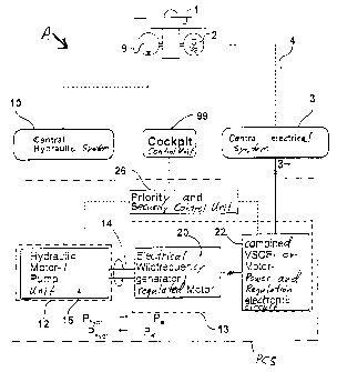
Fig. 4 shows a simplified block circuit diagram giving a general
overview of the power conversion system for the bi-directional
- 16 -
CA 02219293 1997-10-27
conversion of hydraulic power to electrical power and vice versa,
according to the invention. As an example, the present power
conversion system PCS is installed in an aircraft A having an
electrical system 3 and a hydraulic system 10, and primary
s sources for generating or providing the two different energy
types, i.e. electrical energy and hydraulic energy, that are
separately to be introduced into the respective electrical and
hydraulic systems. Namely, the aircraft A has an engine 1, with
a hydraulic source 9 and an electrical source 2 connected to and
~o driven by the engine 1. The hydraulic source 9, for example,
comprises an engine driven main hydraulic pump that sucks hydrau-
lic f luid out of a storage tank or a return f low system, and
pressurizes and pumps the fluid into the hydraulic supply lines
of the hydraulic conduit system 10 of the vehicle. The electri-
cal source 2 for example comprises a three-phase AC generator
which is connected to the electrical distribution system 3 of the
vehicle through a disconnect switch 4. The hydraulic conduit
system 10 comprises an interconnected network or circuit of pipes
or conduits or other hydraulic lines to form a central hydraulic
zo network, while the electrical distribution 3 comprises an elec-
trical interconnection of plural electrical buses to form a
central electrical bus network. It should be understood that the
two engine driven main energy sources 2 and 9 shown here in an
exemplary manner can also be provided in a plural or redundant
z5 manner in connection with plural engines 1 of the vehicle, or may
be distributed over several of such engines.
Most generally, the present power conversion system PCS includes
a hydraulic partial system 12 and an electrical partial
system 13, which are mechanically and preferably rotationally
- 17 -
CA 02219293 1997-10-27
connected to one another by a drive shaft 14 or a gear train or
other mechanical drive transmission, and are respectively con-
nected to the corresponding power systems of the aircraft. The
power conversion system further generally includes a control
s unit 26 especially in the form of a priority and safety switching
unit, which is connected to the hydraulic partial system 12 and
to the electrical partial system 13 for respectively controlling
the operation thereof.
The hydraulic partial system 12 essentially comprises a hydraulic
~o motor/pump unit 15, which may be a hydraulic displacement
machine 15 for example, which includes a rotationally supported
machine element that is provided to be mechanically coupled to
the shaft or the like 14. The primary component of the electri-
cal partial system 13 is an electrical synchronous machine 20,
which includes a generator/motor such as an electrical wild
frequency generator that also functions as a regulated motor 20,
having a rotationally supported machine element that may be
connected to the shaft 14. The electrical partial system 13
further includes a so-called variable speed constant frequency
zo (VSCF) motor power control electronic circuit, embodied as an
electronic control unit 22, which is electrically connected to
the electrical machine 20. The respective rotatably supported
machine elements of the hydraulic and electrical machines 15
and 20 are mechanically and rotatably coupled together by the
z5 shaft 14 or other mechanical drive train in such a manner, with
such matched rotational speeds, that the operating efficiencies
or power conversion operating rates of the two partial systems 12
and 13 are optimized and tuned to one another as needed for the
respective nominal operating power conditions.
- 18 -
CA 02219293 1997-10-27
Further specific details of the construction of the hydraulic and
electrical partial systems 12 and 13, and the functioning of the
elements integrated therein, will be discussed in further detail
below with regard to Fig. 4A. However, additional general as-
s pects of the system will now be described still with reference
to Fig. 4. The partial systems 12 and 13 further include mode-
specific or system-specific switching elements 18 and 21, e.g.
a hydraulic switching arrangement 18 and an electrical switching
arrangement 21, which are shown in Fig. 4A and will be discussed
~o in detail below. The power conversion system PCS further in-
cludes a control unit 26 cooperating with the switching arrange-
ments for controlling and actuating the operation and power flow
in the system. The control unit 26 which is electrically con-
nected for signal transmission to the two partial systems 12
~s and 13, serves the function of the so-called priority and safety
switching circuit, which carries out an overall monitoring of the
system. Namely, the control unit 26 monitors the two partial
systems 12 and 13 and appropriately actuates and controls the
hydraulic or the electrical partial system 12 or 13, or more
2o specifically the hydraulic or the electrical machine 15 or 20,
through the corresponding switching arrangements 18 and 21,
responsive to and based on the detected actual operating condi-
tion respectively of the hydraulic conduit system 10 or the
electrical distribution system 3, and in view of the respective
2s priority allocated to the power consuming devices demanding
electrical or hydraulic power from the respective power systems
at any given time. By means of the actuation and control carried
out by the control unit 26, the switching elements 18 and 21
respectively integrated into the two partial systems 12 and 13
3o are appropriately set or switched, so that one of the two possi-
- 19 -
CA 02219293 1997-10-27
ble bi-directional conversion functions of the system is acti-
vated.
Responsive to and depending upon the above-mentioned operating
status or condition, the control unit 26 controls the operating
s mode of the two partial systems 12 and 13 to carry out a conver-
sion from hydraulic energy to electrical energy, or vice versa,
by converting the received excess type of energy into rotational
mechanical energy and applying this mechanical energy to the
drive transmission or shaft 14 by means of one of the partial
~o systems 12 and 13, and then receiving the rotational mechanical
energy from the transmission or shaft 14 and converting it into
the respective required type of energy in the other one of the
two partial systems 12 and 13, so as to provide the needed type
of energy into either the hydraulic on-board power system or the
electrical on-board power system of a vehicle. For example, the
electrical machine 20 operating as a regulated motor, is driven
by excess electrical energy from the central electrical bus
network 3, to in turn drive the shaft 14 and the hydraulic ma-
chine 14, which transfers hydraulic energy in the form of pumped
2o hydraulic fluid into the hydraulic conduit system or network 10
that is connected to the hydraulic partial system 12 by means of
conduits or the like. On the other hand, for example, available
hydraulic energy from the hydraulic network 10 can be used to
drive the hydraulic machine 15 operating as a hydraulic motor,
2s which in turn transfers the energy from the rotating shaft 14 to
the electrical machine 20 operating as a generator to convert the
rotational mechanical energy of the shaft 14 into electrical
energy. The output of the electrical machine 20 is connected to
the electronic unit 22, which functionally operates as a combined
- 20 -
CA 02219293 1997-10-27
variable speed constant frequency motor power and regulation
electronic control unit, which further processes the electrical
energy output by the generator 20. This further processed elec
trical energy is then transferred to the electrical distribution
s system 3 of the vehicle.
Fig. 4 further shows a general schematic block indicating a
centralized electronic control input and monitoring unit 99, such
as an input keyboard and a display monitor screen, arranged in
the cockpit of the vehicle. This cockpit mounted control unit
~o is connected via an automatic circuit to the control unit 26 in
order to transmit control signals therebetween, for example over
electrical conductors. An operating mode logic circuit of the
control unit 26, in addition to the above-mentioned automatic
circuit, appropriately activates the power conversion system PCS
in a selected mode of the two available bi-directional modes in
the event of a detected pressure drop in the hydraulic system 10
of the vehicle or a voltage drop in the central electrical
system 3 of the vehicle. Through the connection with the cockpit
mounted control unit 99, the operating mode control unit 26 can
zo further activate the operation of the power conversion system PCS
in accordance with input commands entered by the pilot or some
other operator of the system into the cockpit mounted control
unit 99, for example in order to carry out test operations and/or
to switch off or override the automatic operation of the operat
z5 ing mode logic circuit of the control unit 26.
Fig. 4A shows a particular example embodiment of the present
power conversion system for use in an aircraft for example, in
greater detail. As already described above, the present embodi-
- 21 -
CA 02219293 1997-10-27
ment of Fig. 4A includes a hydraulic machine 15 that can operate
as a hydraulic pump or as a hydraulic motor, and an electrical
machine 20 that can operate as a generator or a motor, coupled
together by a rotatable shaft 14. Thus, the conversion operation
s from hydraulic energy to electrical energy or vice versa is
carried out generally as described above.
In the specific embodiment of Fig. 4A, the hydraulic partial
system 12 essentially comprises a hydraulic machine 15 such as
a hydraulic pump~motor 15 in the form of an adjustable hydraulic
~o displacement machine, preferably an axial piston machine with an
adjustable angled disk 15A, of which the stroke volume can be
adjusted by means of an adjustment device 16 such as an adjust-
ment piston 16 or an electro-mechanical adjusting device, as well
as electrical, electronic, or hydro-mechanical regulation units
~s or controllers 17A and 17B connected to be effective on the
adjustment device 16, and the hydraulic switching arrangement 18
connected by conduits to the hydraulic displacement machine 15.
The hydraulic switching arrangement 18 is embodied as, and car-
ries out the function of, a valve assembly, which for example
zo comprises two valves 18A and 18B connected together in parallel
by appropriate conduits or channels. More specifically, the
first valve 18A is a non-return or check valve, while the second
valve 18B is a selectable mufti-position blocking valve or shut-
off valve. The input sides of the two valves 18A and 18B are
2s fluid-f low connected to a f first input branch point 18C that forms
the inlet of the hydraulic partial system 12 that is connected
to a hydraulic conduit 98 of the hydraulic system 10 of the
aircraft, while the outlet or output sides of the two valves 18A
- 22 -
CA 02219293 1997-10-27
and 18B are connected for fluid flow to a second branch
point 18D, which in turn is hydraulically connected to the hy-
draulic displacement machine 15. It should be understood that
the terms "inlet" and "outlet" are used only as a convenient
s reference, but that fluid may f low in both directions through the
valve assembly.
In the present embodiment, the first valve 18A is not electri-
cally activated as it may be in another embodiment, but rather
is a passive spring-biased non-return valve, that is biased by
~o a spring into a passive base position preventing fluid flow from
the hydraulic system 10 to the hydraulic machine 15, and only
opening under the influence of hydraulic pressure to allow fluid
flow from the hydraulic machine 15 to the hydraulic system 10.
In this manner, the non-return valve 18A prevents hydraulic power
15 from being removed from the hydraulic system 10 through the
valve 18A, but allows hydraulic power to be provided back into
the hydraulic system 10 through the valve 18A when the hydraulic
machine 15 is operated in a hydraulic pump mode. The non-return
valve 18A cooperates with the actuatable control valve 18B as
2o follows.
The control valve 18B is normally in a closed or shut-off posi-
tion preventing fluid flow in both directions. When the
valve 18B is actuated, for example by an electrical signal power-
ing an electro-mechanical actuator to open the valve against a
z5 spring bias force, the valve 18B opens to allow fluid flow there-
through from the hydraulic system 10 to the hydraulic machine 15
to activate the hydraulic motor operating mode of the hydraulic
machine 15. In this manner, with such a valve setting, hydraulic
- 23 -
CA 02219293 1997-10-27
power can be removed from the hydraulic system 10 to drive the
hydraulic motor 15 and thus provide mechanical power through the
shaft 14 into the electrical partial system 13 as will be de-
scribed below. The same functions carried out by the two valves
s 18A and 18B can also be carried out by a single, differently
embodied valve, such as a so-called non-return~free flow valve.
In such a single valve, the non-return function of the first
valve 18A would be incorporated into the closed position of the
second valve 18B.
~o The hydraulic partial system 12 operates either as a pressure
regulated pump using the components enclosed within a first
dashed line 19A, or as a rotational speed controlled or secondary
controlled hydraulic motor using the components enclosed within
the second dashed line 19B. Namely, the pressure regulated pump
involves the hydraulic machine as a pump 15, in connection with
a first controller 17A that operates as a constant pressure
controller, and the adjustment device 16, while the hydraulic
motor operation involves the hydraulic machine operating as a
motor 15 in connection with a second controller 17B that operates
zo as a constant rotational speed controller, and the adjustment
device 16. The two controllers 17A and 17B are separately or
independently connected for control signal transmission to the
adjustment device 16. Furthermore, the first controller 17A is
connected to at least one pressure sensor 17A1 that is integrated
2s into a conduit connection between the outlet junction 18D of the
valve arrangement 18 and the hydraulic displacement machine 15,
or alternatively the sensor may be incorporated in the first
controller 17A. Similarly, the second controller 17B is con-
nected to a rotational speed sensor 17B1 which is arranged to
- 24 -
CA 02219293 1997-10-27
sensitively detect and measure the rotational speed of the
shaft 14. These two controllers 17A and 17B can be embodied in
any manner known in the art, for example electrically, electro-
mechanically, or hydro-mechanically, to correspondingly use
s electrical signals and operation, electro-mechanical signals and
operation, or hydraulic signals and operation.
When the hydraulic displacement machine 15 is operating in the
pump mode, the first controller 17A operates as a pressure con-
troller which sensitively detects the output pressure po of the
~o pump 15 and appropriately regulates the operation of the pump 15
via the adjustment device 16 based on the respective output
pressure pa, for example to achieve a constant output pressure
matched to the nominal pressure of the hydraulic system 10. In
this pump operating mode, the hydraulic fluid being provided
under pressure by the pump 15 flows through the non-return
valve 18A into the hydraulic system 10, while the second
valve 18B remains closed. The hydraulic fluid is sucked by the
pump 15 from a return line system lOR and/or a reservoir tank lOT
of the hydraulic system 10. On the other hand, when the hydrau-
20 lic displacement machine 15 is operating in the hydraulic motor
mode, the second controller 17B operates as a rotational speed
controller or regulator, which sensitively detects the rotational
speed nH of the hydraulic motor 15 and appropriately regulates
the operation of the motor 15 via the adjustment device 16 to
zs achieve a constant rotational speed. This motor operating mode
is achieved by activating the second valve 18B to the through-
flow or open valve position so that hydraulic fluid will flow
from the high pressure conduit 98 to the hydraulic motor 15,
- 25 -
CA 02219293 1997-10-27
which is thus driven thereby, whereafter the f luid f lows back
through the return line lOR to the tank 10T.
The second controller 17B can be a hydro-mechanical controller
or regulator, which mechanically senses and reacts according to
s the rotational speed nH. Alternatively, the second control-
ler 17B may be an electro-hydraulic controller using an electri-
cal sensor for measuring the rotational speed nH. These two
controllers 17A and 17B are correlated with or through the valve
assembly 18 and particularly the second valve 18B, and are fur-
~o they selectively operably or switchably connected to the hydrau-
lic displacement machine 15. The first controller 17A can be a
hydro-mechanical or an electronic controller using an electro
hydraulic adjustment mechanism, that is respectively effective
on the adjustment device 16 for the angled disk 15A of the con
15 trollable hydraulic machine 15.
In the embodiment in which the first controller 17A comprises an
electronic controller, two special circuit arrangements or oper-
ating modes are possible. In the first special circuit operation
of the electronic controller 17A, a start-up phase of the pump
2o is carried out in order to run-up the pump of the bi-directional
power conversion system from a standstill to a normal operating
speed in the fastest, load-free manner. To achieve such a start-
up phase the operating mode logic circuit of the control unit 26
provides the appropriate control signals, and the angled disk 15A
2s of the adjustable pump 15 is maintained at a zero or null stroke
setting to allow a load-free operation until the pump 15 substan-
tially reaches a synchronous rotational speed of the electrical
machine 20 of the electrical partial system 13. Only then does
- 26 -
CA 02219293 1997-10-27
the first controller 17A control the operation of the pump 15 so
as to achieve and maintain the desired constant pressure po.
The second special operating mode of such an electronic control-
ler 17A relates to an operation based on a prescribed nominal
s pressure or control pressure. The desired or nominal pressure
may either have a constant value corresponding to the nominal
pressure po of the output of the engine driven main hydraulic
pumps 9A to 9D shown in Figs. 8A to 8C, or may be a variable or
adjustable pressure as will be described below. The constant
~o value, prescribed nominal pressure thus corresponds to the so-
called flat cut-off characteristic of the hydraulic pumps 9A
to 9D, and is prescribed in the first controller 17A via the
operating mode logic circuit of the control unit 26 when the bi-
directional power conversion system is to be operated as a sup-
15 plementary or boosting hydraulic pump for better supporting peak
hydraulic power requirements, while simultaneously operating the
primary hydraulic pumps 9A to 9D in parallel therewith. As
mentioned above, the prescribed nominal pressure po can alterna-
tively have a variable value that is adjusted dependent upon the
zo pump output volume flow, corresponding to the so-called soft cut-
off characteristic of pressure regulated pumps. Such a soft cut-
off prescribed nominal pressure is set in the first
controller 17A via the operating logic circuit of control unit 26
preferably in such situations when the bi-directional power
z5 conversion system is to be used as the sole source or as a re-
placement source of hydraulic power for the hydraulic system,
when the primary pumps 9A to 9D have failed or are otherwise
unavailable, and if the maximum motor power required to achieve
this shall be more sharply or strongly limited.
- 27 -
CA 02219293 1997-10-27
The electrical partial system 13 as shown in Fig. 4A essentially
comprises the electrical machine 20, the second operation spe-
cific switching arrangement 21, and the electronic unit 22. The
electrical machine 20 is, for example embodied as an AC synchro-
s nous machine which operates either as an electrical motor or an
electrical generator in the system. The second operation spe-
cific switching arrangement 21 is a multi-pole electrical pole
reversing switching arrangement, whereby the contacts or connec-
tions of the electronically or electrically controllable devices
~o of the synchronous machine and of the mufti-pole electrical pole
reversing switching device or arrangement 21 are connected to a
voltage regulator. The electronic unit 22 is a generally known
power electronics control and processing unit comprising, in
order, and connected electrically in series, a rectifier, a DC~AC
converter or inverter, and a filter, each having respective
output stages. The three-phase AC contacts of the synchronous
machine are connected to the corresponding contacts, namely the
base or root contacts of the switching member, of the pole rever-
sal switching device 21. The main input contacts of the recti-
zo fier are connected to one of the switch selectable AC contacts
of the mufti-pole switching member of the pole reversal switching
arrangement 21.
The other AC contacts of the pole reversal switching
arrangement 21, which has at least two switching positions, are
2s electrically connected to the conductor contacts of an AC power
connection, which in turn is electrically connected through a
disconnect switch 23A to a first AC bus 3A. In a similar manner,
the main output contacts of the filter output stage of the power
electronics unit 22 are connected to a second AC interconnection,
- 28 -
CA 02219293 1997-10-27
which in turn is connected through a second disconnect switch 23B
to a second AC bus 3B. It is alternatively possible to provide
a single electrical bus instead of the two independent buses 3A
and 3B, in which case it is further possible to replace the two
s disconnect switches 23A and 23B by a single disconnect switch.
As a further variant embodiment in the construction and function-
ing of the power electronics unit 22, it may be desirable to
provide appropriate switching stages to reverse the series ar-
rangement of the rectifier and the DC/AC converter, in order to
~o achieve a controlled or regulated start-up phase of the electri-
cal machine 20 in the operating mode when it is to be driven as
a motor using electrical power from the power system 3. Namely,
in such a case the rectifier stage would have to be powered, i . a .
connected at its input to the electrical power system 3, while
15 the output of the rectifier would be provided to the DC/AC con-
verter, from which the output would be connected to the electri-
cal machine 20.
It should further be understood within the scope of the invention
that the electrical machine 20 and/or the on-board electrical
zo power system 3 are not necessarily embodied for three-phase AC
power. Instead, it is also possible to use any other desired
known electrical machine 20, for example a single-phase machine,
that can be operated as either a motor or a generator.
In the event that the electrical machine 20 and the on-board
z5 electrical power system 3 are not tuned or matched to one an-
other, then the power electronics unit 22 must be switched to
operate as a control and commutation electronic circuit for
- 29 -
CA 02219293 1997-10-27
driving the electrical machine 20 operating as a motor, whereby
the power electronics unit 22 would be switched essentially in
a reverse direction, so to speak, in comparison to the above
described operation for a controlled start-up phase of the motor.
s As a further alternative, for a relatively low power electrical
machine 20, it is also possible to operate the electrical mach-
ine 20 connected directed to a single-phase or multi-phase AC
voltage power net, without using the otherwise bi-directionally
operating power electronics unit 22. Moreover, the system can
~o be operated on a DC voltage power net, whereby the DC/AC con-
verter is bypassed by means of appropriate switches, while the
system is operating in the generator mode. In any event, the
DC/AC converter is required for carrying out electronic commuta-
tion while the electrical machine 20 is operating in a motor
mode, whereby it is understood that the DC/AC converter can be
completely eliminated or avoided if a mechanical commutator is
used.
By means of the pole reversal switching arrangement 21, the
electrical machine 20 may be switched to operate either as a
zo motor or as an AC generator, in two modes as follows. When the
switching element of the pole reversal switching arrangement 21
is switched into a first or upper switching position in the view
schematically shown in Fig. 4A, then AC power flows from the on-
board electrical system 3 of the aircraft, namely from the first
z5 AC bus 3A through the first disconnect switch 23A through the
pole reversal switching arrangement 21 to the AC synchronous
electrical machine 20, which thus operates as a motor using the
available electrical power from the on-board electrical system 3.
- 30 -
CA 02219293 1997-10-27
On the other hand, if the switching element of the pole reversal
switching arrangement 21 is switched to the second or lower
switching position in the view shown in Fig. 4A, then the output
contacts of the electrical machine 20 operating as an AC genera-
l for will be connected to the power electronics unit 22 and from
there through the second disconnect switch 23B to the second AC
power bus 3B of the electrical system 3 of the aircraft. In this
operating mode, the electrical machine 20 operates as an AC
generator having a constant effective voltage U and a constant
~o frequency f, if the drive transmission or shaft 14 is driven by
the hydraulic machine 15 operating as a hydraulic motor, and the
rotating shaft 14 in turn drives the electrical machine 20 as a
generator. This second operating mode, namely the generator
operating mode, and the associated switching condition of the
15 pole reversal switching arrangement 21, generally corresponds to
the known functional principle of an electrical system for gener-
ating a constant voltage and constant frequency output while
having a variable or oscillating input drive rotational speed nE,
i . a . a variable speed constant frequency ( VSCF ) electrical gener-
zo ation principle. In this switching condition, the multi-poled
pole reversal switching arrangement 21 closes a circuit or con
tact with the respective individual pole switching elements
between the AC contacts that are connected to the main input
contacts of the rectifier, and the separate respective root or
z5 base contacts.
Fig. 4A further shows a voltage regulator 20A connected between
the electrical machine 20 and the input of the power electronics
unit 22, which can be any known voltage regulator for achieving
the voltage regulated operation of the electrical machine 20 in
- 31 -
CA 02219293 1997-10-27
the manner discussed above. In the present example embodiment,
the output of the electrical machine 20 operating as a generator
is a three-phase AC electrical current having a constant voltage,
but a variable frequency, which is rectified to provide at the
s output of the rectifier a three-phase rectified current having
a constant voltage level, which is then further processed through
the DC/AC converter and filter stages to provide a final output
of a three-phase AC current having a voltage of 115200 V and a
frequency of 400 Hz that is further to be provided into the
~o aircraft electrical system 3.
The hydraulic partial system 12 and the electrical partial
system 13 are mechanically connected together through the drive
transmission or the shaft 14, which preferably has an adjustable
transmission ratio such that the hydraulic motor rotational
speed nH of the hydraulic machine 15 can be matched, i . a . stepped
up or stepped down, as necessary relative to the drive rotational
speed nE of the electrical machine 20, in order to provide opera-
tion with the best possible partial efficiencies within the two
partial systems 12 and 13, namely within the two machines 15
2o and 20, while operating at the nominal power level. In order to
achieve this, the drive transmission or shaft 14 may comprise any
known mechanical power transmission arrangement, including
switchable gear drives, constantly variable transmissions, and
the like.
z5 The operating mode control of the bi-directional power conversion
system PCS is achieved by the above-mentioned operating mode
logic circuit, which may be an electrical or electronic logic
circuit, integrated into the control unit 26. A sensitive pres-
- 32 -
CA 02219293 1997-10-27
sure sensor 24A1 arranged in the hydraulic system 10 of the
aircraft is connected to the control unit 26 via a dataline 24A
which thus provides pressure dependent sensor signals to the
control unit, while respective electrical sensors 24C1, 24B1
s arranged to sense the electrical status of the two AC buses 3A
and 3B are connected to the control unit 26 via datalines 24C
and 24B which thus provide voltage dependent sensor signals to
the control unit. Furthermore, the above-mentioned cockpit
control and input unit 99 is connected to the control unit 26 via
~o a dataline 27. The operating mode logic circuit within the
control unit 26 evaluates and processes the various input sig-
nals, and responsively provides logical switching signals 25 that
are provided to appropriately control the hydraulic valve ar-
rangement 18 and the electrical pole reversal switching arrange-
ment 21 of the two partial systems 12 and 13 in order to activate
either an electrical motor and hydraulic pump operating mode or
a hydraulic motor and electrical generator operating mode.
The operating mode logic circuit advantageously may comprise an
automatic circuit (not shown), which automatically activates the
zo bi-directional power conversion system in the proper operating
mode upon the occurrence of a pressure drop in the hydraulic
system 10 of the aircraft or a voltage drop on the power buses 3A
or 3B of the electrical system 3 of the aircraft. As described
above, pilot-entered input signals or other data provided by the
z5 cockpit unit 99 are received and evaluated by the operating mode
logic circuit through the conductor 27, for example to carry out
a test operation of the system or to override or switch off the
operating mode activated by the automatic circuit. Moreover, it
may advantageously be provided that various measured signals for
- 33 -
CA 02219293 1997-10-27
monitoring the operation of the hydraulic partial system and the
electrical partial system are evaluated in the operating mode
logic circuit in order to ensure that the respective system is
functioning correctly. In the event that the measured parameters
s deviate from allowable system values, i.e. reach unacceptable
system values, then the automatic circuit is switched off, an
error condition is indicated, for example on the pilot control
unit 99, and the entire system is switched off or placed into
suspended operation.
~o With the above-described structural arrangement and operation of
the bi-directional power conversion system shown in Fig. 4A, it
is possible to operate the system in two modes. In the first
generator operating mode, hydraulic energy is converted into
electrical energy, which is supplied into the second power
15 bus 3B, in the event that the primary electrical source such as
the primary generators that ordinarily provide power to the power
bus 3B either have failed or provide an inadequate amount of
power to supply the power demand, i.e. the power being consumed
by all of the power consuming devices connected to the respective
zo power bus. Alternatively, the power conversion system can be
operated in a second operating mode, wherein electrical energy
taken from an intact operational electrical power bus 3A is
converted into hydraulic energy in the form of pumped hydraulic
fluid that is delivered into the hydraulic system 10. The bi-
25 directional power conversion system is constantly connected to
a prescribed on-board hydraulic system, in a controlled manner
through the valve assembly 18, while one or more of various power
buses 3A and 3B, for example may selectively be connected to the
electrical side of the power conversion system according to the
- 34 -
CA 02219293 1997-10-27
respective requirements or application at hand, through the
electrical disconnect switches 23A and 23B.
Fig. 5 shows a further varied embodiment of the bi-directional
power conversion system. In Fig. 5, the electrical partial
s system 13 does not include a power electronics unit 22, in con-
trast to the embodiment shown in Figs. 4 and 4A, wherein such an
electronics unit 22 is used for producing a stable output fre-
quency even in the event of a fluctuating or oscillating rota-
tional speed of the shaft 14. Thus, the present embodiment of
~o the power conversion system is advantageous in situations in
which the rotational speed of the hydraulic machine 15, and
especially of the shaft 14, can be regulated with sufficient
precision or accuracy even in the event of strongly varying
loads, in order to provide the necessary accuracy and constancy
of the output frequency of the output electrical power being
generated. In other words, in situations in which the rotational
speed of the generator 20 can be regulated to a constant nominal
value through appropriately controlling the speed of the
shaft 14, then electrical frequency regulation is not necessary.
zo All other components and characteristics of the embodiment de-
scribed in connection with Fig. 4A also apply to the present
embodiment according to Fig. 5.
Fig. 6 is a simplified schematic view of a particular bi-direc-
tional power conversion system 40, of which the individual fea-
z5 tures were shown and described in detail in connection with
Figs. 4A and 5. The present simplified schematic of the particu-
lar architecture of the system is being used for describing
additional embodiments relating to various on-board power system
- 35 -
CA 02219293 1997-10-27
configurations. The electronic power regulation unit 22 is
optional if the hydraulic machine 15 operating as a hydraulic
motor in the generator mode of the system is regulated with
sufficient precision and constancy to meet the needs for a suffi-
ciently exact constant and stable output frequency of the elec-
trical machine 20 operating as a generator.
Figs. 7A and 7B show two different operations or operating modes
of the presently defined bi-directional power conversion sys-
tem 40, which may be selectively activated as needed, depending
~o on the operating status of the hydraulic system 10 and the elec-
trical system 3 of an aircraft having two engines 1A and 1B,
whereby a primary generator 2A connected to and driven by the
engine 1A provides primary electrical power into the electrical
system 3, while a primary hydraulic pump 9B is connected to and
driven by the engine 1B to pressurize hydraulic fluid into a
hydraulic conduit 98 of the hydraulic system 10.
Fig. 7A shows the situation in which the engine 1B and thus also
the engine-driven hydraulic pump 9B has failed, or is switched
off while the aircraft is parked or operating on the ground. In
zo this situation, the power conversion system 40 will convert
available electrical power into hydraulic power in order to
provide the necessary hydraulic power in the hydraulic system 10.
The present power conversion system 40 thus replaces the mono-
functional electrically driven hydraulic pumps of known prior art
2s arrangements, for example the pumps of the independent
systems 11A, 11B and 11C as shown and described with reference
to Figs. 1 to 3 above. Fig. 7B shows the situation in which the
engine 1A and thus also the generator 2A connected thereto have
- 36 -
CA 02219293 1997-10-27
failed, or been switched off while the aircraft is parked or
operating on the ground. In this situation, available hydraulic
power will be converted into electrical power and fed into the
AC power bus 3A and especially the critical or essential compo-
s nents AC power bus 3E in order to provide the required electrical
power in the electrical system 3. The operating arrangement
depicted in Fig. 7B is also for providing auxiliary or supplemen-
tal electrical power to help cover the peak electrical power
demands that might be inadequately satisfied by the primary
~o generator 2A. Thus, it can be seen that the present bi-direc-
tional power conversion system 40 replaces the mono-functional
hydraulically driven constant speed motor generators or emergency
power generators 6 as shown and described above with reference
to Figs. 1 to 3. The two operating situations shown in Figs. 7A
and 7B will now each be described in detail.
In the configuration or switching condition of the bi-directional
power conversion system 40 as shown in Fig. 7A, the following
electrical connections exist between the various components. The
first engine driven AC generator 2A, which is one of the primary
2o electrical power sources, is electrically connected through the
first disconnect switch 4A to the AC power bus 3A, which in turn
is electrically connected through an appropriate AC conductor and
a disconnect 23A to the electrical switching arrangement 21
incorporated in the bi-directional power conversion system 40.
z5 The switching arrangement 21 is switched to bypass the power
electronics unit 22, so that AC electrical power is directly
provided from the AC bus 3A to the electrical machine 20 through
the switching arrangement 21, whereby the electrical machine 20
operates as an electrical motor to drive the rotational shaft 14.
- 37 -
CA 02219293 1997-10-27
The hydraulic machine 15, which now operates as a hydraulic
pump 15, has its output connected to a pressure line 98 so that
pressurized hydraulic fluid and thus hydraulic power can be
transferred into the hydraulic system 10 in the event of the
s failure of the engine driven hydraulic pump 9B or even the entire
engine 1B, or in the event of a deficiency in the hydraulic power
provided by the hydraulic pump 9B.
The circuit arrangement shown in Fig. 7B further includes the AC
power bus AC ESS 3E that provides emergency electrical power in
~o a limited manner to those electrical devices that are critical
or essential for operation of the aircraft. The essential or
critical power bus 3E is connected to the above-mentioned usual
AC power bus 3A by a conductor line with an interposed disconnect
switch 23C. In the situation and switching condition shown in
15 Fig. 7B, hydraulic power is provided by the engine driven primary
hydraulic pump 9B into the pressurized conduits 98 of the hydrau-
lic system 10. The hydraulic machine 15 operating as a hydraulic
motor 15 extracts hydraulic energy from the hydraulic pressurized
conduits 98 for driving the hydraulic motor 15 which in turn
zo drives the rotary shaft 14. The shaft then drives the electrical
machine 20, now operating as a generator 20, such that the hy-
draulic power is converted to electrical power, which flows
through the electrical switching element 21, to be further pro-
cessed through the power electronics unit 22 and ultimately
2s provided to the AC power bus 3A and further to the critical or
essential AC power bus 3E. This illustrated situation assumes
that the primary electrical power generator 2A or the entire
engine 1A has failed or is not operating.
- 38 -
CA 02219293 1997-10-27
The use of the defined bi-directional power conversion system 40
as described above in connection with Fig. 6 instead of a mono-
functional electrically driven hydraulic pump (as in the conven-
tional independent hydraulic system 11A of Figs 1 to 3 ) and a
s mono-functional hydraulically driven conventional constant speed
motor/generator (operating as an emergency generator device 6 in
Figs. 1 to 3) is also applicable to hydraulic systems using a
further auxiliary or supplemental ram air turbine driving a
hydraulic pump 7 as shown in Fig. 7C. As discussed above, such
~o hydraulic systems are primarily provided with hydraulic power in
the form of pressurized hydraulic fluid from an engine driven
hydraulic pump such as pumps 9A to 9D of above Figs . 1 to 3,
while the ram air turbine with its connected hydraulic pump 7
forms an alternative, auxiliary, or emergency energy source. In
15 the conventional arrangement, the emergency hydraulic power
provided by the ram air turbine and pump 7 is converted into
electrical energy by the constant speed motor generator (CSMG)
device 6. By replacing such a CSMG device 6 with the bi-direc-
tional power conversion system 40 according to the invention, the
2o advantage is achieved that the power conversion system 40 can
selectively operate as the primary hydraulic pump or as an emer-
gency generator depending upon the selected operating mode.
The circuit arrangement of Fig. 7C shows that the hydraulic
machine 15 of the defined power conversion system 40 is connected
2s to a pressure line 98, which in turn is connected to the hydrau-
lic pump 7 that is mechanically connected to and driven by the
ram air turbine. The electrical switching element 21 is sepa-
rately connected to the first AC bus 3A, and through the power
electronics unit 22 to the critical or essential AC bus 3E. An
- 39 -
CA 02219293 1997-10-27
electrical multi-path switch 8, which is shown as a single pole
switch having four electrical contacts, is interposed between and
among the first AC bus 3A, the essential or critical bus 3E, and
a second AC bus 3B. Two contacts of the switch 8 are connected
s together by a conductor bridge, which in turn is connected to the
critical or essential bus 3E. The other two contacts of the
switch 8 are separately or independently connected respectively
to the first AC bus 3A and the second AC bus 3B. Thus, by appro-
priately switching the mufti-path switch 8, the critical or
~o essential bus 3E may selectively be coupled with the first AC
bus 3A or the second AC bus 3B or neither bus 3A or 3B . The
first AC bus 3A is further electrically connected to the primary
generator 2A that is driven by the engine lA.
In the event that the primary hydraulic pump 9A driven by the
engine lA is inoperative or provides inadequate hydraulic power,
the system will operate according to any one of the following
possibilities. The ram air turbine driving the hydraulic pump 7
will provide auxiliary or emergency hydraulic power into the
hydraulic system 10. If the ram air turbine with pump 7 provides
zo an adequate amount of hydraulic power to supply all the hydraulic
power needs of the hydraulic system 10, and the generator 2A
provides sufficient electrical power for the electrical needs in
the electrical system 3, then the power conversion system 40 may
be inoperative or in a standby mode. However, if the auxiliary
z5 or emergency hydraulic power provided by the ram air turbine and
pump 7 is insufficient, while excess electrical power is avail-
able on the electrical power system 3, then the excess electrical
power will be used to drive the electric machine 20 operating as
an electric motor, which in turn rotationally drives the shaft
- 40 -
CA 02219293 1997-10-27
or transmission 14 to drive the hydraulic pump 15, thereby con-
verting electrical energy to hydraulic energy which is supplied
into the hydraulic power system 10. On the other hand, if there
is an excess of hydraulic power available in the hydraulic
s system 10, and inadequate electrical power in the electrical
system 3, for example due to the failure of the generator 2A, or
if the electrical devices connected to the essential AC bus 3E
are receiving inadequate electrical power and have a higher
priority than the hydraulic devices, then hydraulic power will
~o be extracted from the high pressure conduit 98 to drive the
hydraulic motor 15, and in turn drive the electrical generator 20
through the shaft 14 so as to provide emergency electrical power
that is fed into the essential AC bus 3E and/or the first and
second AC buses 3A and 3B, depending on the switching positions
~S of the electrical switching arrangement 21 and the multi-path
switch 8.
It is further illuminating of the invention to note that various
combinations of the above-described basic principles of utilizing
the present bi-directional power conversion system can be used
2o depending upon the particular application at hand in multiply
redundant hydraulic and electrical energy or power systems on-
board vehicles of all types, and especially aircraft. Use of the
present bi-direction power conversion system to replace indepen-
dent mono-functional or mono-directional conversion apparatus of
z5 the prior art systems allows a greater reliability, safety and
redundancy to be achieved. For example, using the present bi-
directional power conversion system, each source of hydraulic
power on-board the aircraft is also available as a secondary or
redundant source for ultimately producing electrical power.
- 41 -
CA 02219293 1997-10-27
Similarly, each primary source of electrical power on the air-
craft is also available as a secondary redundant source for
ultimately producing hydraulic power. Use of the present bi-
directional power conversion system thereby overcomes the known
s disadvantages of the conventional system concepts shown in
Figs. 1 to 3. Figs. 8A, 8B and 8C show example embodiments of
different system configurations using the present power conver-
sion apparatus instead of the known typical system configurations
according to Figs. 1 to 3.
~o In comparison to the arrangement of Fig. 3, the arrangement of
Fig. 8 uses the present bi-directional power conversion sys-
terns 40A, 40B and 40C to replace all of the electrically driven
hydraulic pumps of the conventional independent hydraulic
systems 11A " ', 11B " ' as well as the hydraulic power transfer
unit 121' ' ' of the conventional arrangement according to Fig. 3 .
An advantage of the present use of the bi-directional power
conversion systems 40A, 40B and 40C is that the systems simulta-
neously serve the function of an alternative or emergency elec-
trical generator or power source. Thus, the overall redundancy
zo and back-up safety of the system is improved, i.e. the likelihood
of a non-correctable failure or lack of electrical power or
hydraulic power is significantly reduced. A further advantage
of the present system of Fig. 8A is that it avoids the need of
using one of the conventional devices, namely the CSMG
z5 device 6 " ' including an integrated emergency power generator
that is necessary in the conventional arrangement according to
Fig. 3.
- 42 -
CA 02219293 1997-10-27
Moreover, it is possible according to invention, during flight
or driving operation of the vehicle, to operate the bi-direc-
tional power conversion systems 40B and 40C in a manner so as to
provide supplemental electrical or hydraulic power when necessary
s to meet peak demand conditions. Thus, the power conversion
systems 40B and 40C can be operated as auxiliary generators
providing electrical power onto the buses 3A and 3B, while ex-
tracting or utilizing available hydraulic power from the hydrau-
lic systems lOB and 10C. On the other hand, the power conversion
~o systems 40B and 40C can be operated as auxiliary hydraulic pumps
to provide additional hydraulic power on the hydraulic
systems lOB and lOC while extracting or using available electric
power from the power buses 3A and 3B. Such an embodiment varia-
tion according to the invention may be advantageously used when
~s the peak electrical power needs do not arise simultaneously with
the peak hydraulic power needs in the respective power systems
during normal operating conditions.
Thus, it is possible to dimension and design the primary energy
sources such as hydraulic pumps 9A and 9B and electrical genera-
2o tors 2A and 2B to respectively provide the necessary nominal
power for the normal or nominal power consumption level, with a
certain safety margin, without needing to provide respective
power coverage for the peak loads. In other words, the auxiliary
electrical power and hydraulic power available from the respec-
25 tive other power system through the bi-directional power conver-
sion units 40B and 40C can be taken into account when designing
the power systems and particularly the primary power sources.
The resulting advantage is that the installed power generation
capacity can be reduced, thereby achieving savings in cost and
- 43 -
CA 02219293 1997-10-27
weight, as long as the total power available including the auxil-
iary power provided through the power conversion systems is
adequate to cover the total peak demands arising at any time in
either power system. Alternatively, it could be considered that
s the inventive arrangement using the power conversion systems is
able to cover or provide adequate power for higher peak load
conditions than could be covered by the primary hydraulic or
electrical power provided by the pumps 9A and 9B and the genera
toys 2A and 2B. In this manner, fewer restrictions are placed
~o on the operating possibilities of the aircraft.
Fig. 8B shows an inventive arrangement, which in comparison to
the conventional arrangement of Fig. 2 replaces all of the elec-
trically driven pumps 11A" to 11C" by the inventive bi-direc-
tional power conversion systems 40A to 40C. Moreover, in compar-
ison to the conventional system of Fig. 2, the system of Fig. 8B
uses only one primary hydraulic pump 9A and 9B per engine 1A
and 1B, while each primary pump 9A and 9B has approximately twice
the rated hydraulic power output of the conventional pumps, i.e.
a double hydraulic flow volume. The load applied to the engines
2o for the shaft power for driving the pumps and generators is not
significantly altered. However, further advantages are achieved
because all of the power conversion systems 40A to 40C can be
operated either as electrically driven hydraulic pumps or as
alternative or emergency power generators.
2s The advantages of the inventive arrangement according to Fig. 8B
compared to the conventional arrangement of Fig. 2 are as fol-
lows. First, two independent hydraulic systems 10A and lOB are
available, each having or providing double capacity hydraulic
- 44 -
CA 02219293 1997-10-27
power, while in contrast, in the conventional arrangement of
Fig. 2 only the central hydraulic system 10B" has the double
hydraulic power available. Secondly, the inventive arrangement
according to Fig. 8B avoids the need of installing hydraulic
s conduits from the central hydraulic system lOB arranged in the
central landing gear bay outboard to the two engine driven
pumps 9B and 9C as is necessary in the arrangement of Fig. 2,
whereby the inventive arrangement reduces the total weight, cost,
and complexity of the installed hydraulic system. Third,
~o the CSMG device 6" including the emergency power generator as
used in the system of Fig. 2 can be completely omitted. Fourth,
the reliability of the availability of the electrical and hydrau-
lic power is significantly improved through the use of the bi-
directional power conversion systems 40A to 40C, i.e. the likeli-
15 hood of a power failure on either one of the power systems is
considerably reduced. Fifth, just as described above with refer-
ence to Fig. 8A, it is possible to cover the peak power demands
arising on the electrical power buses or in the hydraulic power
system during certain flight phases by appropriately operating
2o the power conversion systems 40A to 40C, and it is even possible
to take the additional power available through the power conver
sion systems into account when designing the primary power supply
systems, to achieve cost and weight savings by providing a re
duced total installed nominal power capacity of the primary pumps
2s and generators.
In the arrangement shown in Fig. 8C, in comparison to that shown
in Fig. l, all the electrically driven pumps 11A' to 11C' have
been replaced by bi-directional power conversion systems 40A
to 40C. Moreover, in comparison to the typical conventional
- 45 -
CA 02219293 1997-10-27
arrangement shown in Fig. 1 having hydraulic pumps and electrical
generators mounted on four engines, in the present arrangement
only one respective generator 2A and 2D having twice the normal
or conventional nominal output power is respectively mounted on
s only two engines 1A and 1D, while two pumps 9A, 9B, 9C and 9D are
respectively mounted on each one of the other two engines 1B
and 1C. The total load applied to the engines through the shaft
power extracted for driving the pumps and generators is not
substantially different from that in the conventional arrangement
~o of Fig. 1. However, advantages are achieved because all of the
power conversion systems 40A to 40C can be operated as either
electrically driven pumps or alternative or emergency generators.
The advantages of such an inventive arrangement using bi-direc-
tional power conversion systems 40A to 40C as shown in Fig. 8C,
in comparison to the arrangement shown in Fig. 1 are as follows .
First, with the same available electrical and hydraulic nominal
power respectively provided to the electrical power buses 3A
and 3D and to the hydraulic systems 10A to 10C, the present
arrangement can omit conduit connections between two pumps pro-
2o vided on the inner and outer engines in the conventional air-
craft, as well as the electrical cable connections running from
the fuselage to the two inner engines 1B and 1C for the two
generators in the conventional arrangement, thereby achieving
cost and weight savings. Second, the CSMG device 6' including
2s the emergency generator as used in the arrangement of Fig. 1 can
be omitted. The reliable availability of electrical and hydrau-
lic power is considerably improved by the use of bi-directional
power conversion systems 40A to 40C, i.e. the likelihood of a
failure of the two types of power is considerably reduced.
- 46 -
CA 02219293 1997-10-27
Fourth, as discussed above in relation to the arrangement shown
in Figs. 8A and 8B, it is possible to cover the peak power re-
quirements arising on the power buses or in the hydraulic system
of the vehicle during certain operating phases thereof by appro-
s priately connecting and operating the power conversion
systems 40A to 40C, or the additional power capacity provided
through the power conversion systems 40A to 40C may be taken into
account when designing the primary power supply system, to
achieve weight and cost savings by reducing the total installed
~o nominal power capacity of the primary hydraulic pumps and primary
electrical generators.
Using the inventive bi-directional power conversion systems
according to the invention, it is possible to achieve many dif-
ferent configurations of energy conversion systems between hy-
~s draulic and electrical emergency power supplies in generally any
type of vehicle construction. While the present inventive ar-
rangements are particularly suitable for use in aircraft due to
the safety, reliability, and redundancy considerations, the use
in aircraft is not a limitation for achieving the advantages of
2o the invention. The present bi-directional power conversion
system can effectively replace, and take over the functions of,
any conventional electrically driven hydraulic pump as well as
any conventional hydraulic-electrical alternative or emergency
power generators, as are used in conventional aircraft construc
ts tion for example.
Generally, the system comprises a hydraulic motor that can also
be operated or driven as a pump, and an electrical gener-
ator~motor connected thereto via a drive train or shaft. An
- 47 -
CA 02219293 1997-10-27
electrical converter unit produces an on-board voltage having a
constant frequency from the three-phase AC voltage having a
variable frequency produced by the generator operating in an
emergency power mode. In the event that additional hydraulic
s power is required, this electrical converter unit or computer can
be circuit connected as a converter powered from the on-board
power net, to in turn power and drive the rotational speed regu-
lated electric motor, which then drives the hydraulic pump
through the shaft. In this context, the control and conversion
~o electronics, which are especially embodied as bi-directionally
functional electronics, are carried out or based on highly inte-
grated power semiconductors. In addition to the rectifier func-
tion carried out by the control electronics in accordance with
variable speed constant frequency (VSCF) technology for the
15 generator, in order to avoid the need of hydro-mechanical regula-
tion of the rotational speed, the power control electronics can
also be used for regulating the motor operation, for example to
achieve a regulated run-up of the motor in conditions when addi-
tional or emergency hydraulic power is needed.
zo The use of the present bi-directional power conversion system
makes it possible to achieve various architectures of on-board
electrical and hydraulic power systems that achieve and embody
a reduction and savings on the total number of components and
interconnections needed in the conventional system arrangement,
2s while also achieving a comparable or improved reliability of the
overall power supply. Moreover, in comparison to the conven-
tional system arrangements, the present system achieves savings
in weight, complexity, maintenance requirements, production costs
and operating costs. Also, such bi-directional power conversion
- 48 -
CA 02219293 1997-10-27
systems allow peak power loads to be managed or covered with an
adequate power capacity without needing to provide nominal in-
stalled capacity of each type, i.e. electrical and hydraulic, to
cover the respective hydraulic and electrical peak loads, while
s conventional power management concepts are either limited to the
particular energy type that is being managed or require separate
distinct components or systems for carrying out the power conver-
sion in two opposite directions between two types of power.
The present bi-directional power conversion systems are effective
~o for converting electrical energy into mechanical energy, and
further converting that mechanical energy into hydraulic energy,
and vice versa between the respective inputs and outputs of the
power conversion system, and thus for correspondingly transfer-
ring energy or power in either selected direction from one power
~s system to the other. Using such bi-directional power conversion
systems, and any of various embodiments or arrangements thereof,
it is possible to technologically integrate electrical and hy-
draulic emergency or alternative energy sources, which at present
are realized in conventional power systems by individual or
2o separate energy converters, e.g. electrically driven hydraulic
pumps and hydraulically driven emergency generators.
It is expected in the future that the various on-board systems
of modern land, water, and air vehicles will have ever higher
demands for hydraulic and electrical power, especially because
z5 the present trends call for increasing the travel distances and
reducing the total weight of the respective vehicles. In the
context of commercial passenger and transport aircraft, and
especially large aircraft such as future high capacity aircraft
- 49 -
CA 02219293 1997-10-27
or multi-deck aircraft, the on-board power requirements can be
expected to increase greatly because the on-board power require-
ments increase more than proportionally with the increase in the
total size of the aircraft. Moreover, future on-board energy
s systems are needed, which will achieve a time-relative and energy
source-relative compensation or handling of the peak power loads
arising in the power supply network. These needs can be met
using the present bi-directional power conversion systems inte-
grated into a modern power management system, because in contrast
~o the conventional systems are necessarily always designed to
provide adequate respective capacity for the electrical and
hydraulic peak power loads, further in consideration of the
necessary redundancy.
Although the invention has been described with reference to
~s specific example embodiments, it will be appreciated that it is
intended to cover all modifications and equivalents within the
scope of the appended claims. It should also be understood that
the present disclosure includes all possible combinations of any
individual features recited in any of the appended claims.
- 50 -