Language selection

Search

Patent 2219369 Summary

Third-party information liability

Some of the information on this Web page has been provided by external sources. The Government of Canada is not responsible for the accuracy, reliability or currency of the information supplied by external sources. Users wishing to rely upon this information should consult directly with the source of the information. Content provided by external sources is not subject to official languages, privacy and accessibility requirements.

Claims and Abstract availability

Any discrepancies in the text and image of the Claims and Abstract are due to differing posting times. Text of the Claims and Abstract are posted:

  • At the time the application is open to public inspection;
  • At the time of issue of the patent (grant).
(12) Patent: (11) CA 2219369
(54) English Title: HYDRAULICALLY-OPERABLE LOCKING DIFFERENTIAL INCLUDING ADJUSTABLE RETAINER RING DUCTING
(54) French Title: DIFFERENTIEL BLOCABLE AMELIORE A COMMANDE HYDRAULIQUE COMPORTANT UNE BAGUE DE RETENUE A CONDUIT REGLABLE
Status: Expired and beyond the Period of Reversal
Bibliographic Data
(51) International Patent Classification (IPC):
  • F16H 48/22 (2006.01)
  • F16H 48/08 (2006.01)
  • F16H 48/32 (2012.01)
  • F16H 48/40 (2012.01)
(72) Inventors :
  • SOWA, DONALD S. (United States of America)
  • DETTORE, VINCENT C. (United States of America)
(73) Owners :
  • TRACTECH INC.
(71) Applicants :
  • TRACTECH INC. (United States of America)
(74) Agent: BORDEN LADNER GERVAIS LLP
(74) Associate agent:
(45) Issued: 2004-09-14
(22) Filed Date: 1997-11-13
(41) Open to Public Inspection: 1998-06-19
Examination requested: 2001-07-19
Availability of licence: N/A
Dedicated to the Public: N/A
(25) Language of filing: English

Patent Cooperation Treaty (PCT): No

(30) Application Priority Data:
Application No. Country/Territory Date
08/769,367 (United States of America) 1996-12-19

Abstracts

English Abstract

An improved hydraulically-operable locking differential includes a retainer ring that is threadably connected with the axle housing for adjustably supporting the bearings at one end of a differential casing. which retainer ring contains ducting for supplying pressure fluid to a hydraulic actuator contained within the casing. thereby to activate a friction pack assembly to lock a side gear of the differential to the differential casing. The ducting for the hydraulic fluid includes a first passage contained in the retainer ring. a second passage contained in and extending longitudinally of a tubular end portion of the casing, and a third passage which affords continuous communication between the first and second passages during rotation of the casing relative to the axle housing.


French Abstract

Un différentiel blocable amélioré à commande hydraulique comprend une bague de retenue pouvant être reliée par vissage au carter d'essieu pour supporter de manière réglable les roulements à une extrémité d'un boîtier de différentiel dont la bague de retenue comprend un conduit pour alimenter un liquide de pression à un actionneur hydraulique contenu dans le boîtier pour activer ainsi un ensemble de frottement pour verrouiller un engrenage latéral du différentiel au boîtier de différentiel. Le conduit de liquide hydraulique comprend un premier passage contenu dans la bague de retenue, un deuxième passage contenu dans et s'étendant longitudinalement suivant une partie d'extrémité tubulaire du boîtier, et un troisième passage qui permet une communication continue entre les premier et deuxième passages lors de la rotation du boîtier par rapport au carter d'essieu.

Claims

Note: Claims are shown in the official language in which they were submitted.

8
CLAIMS:
1. A locking differential for driving a pair of axially aligned output shafts
from a
rotatably driven drive shaft, said differential being adapted for insertion
within a hollow
differential axle housing containing a pair or aligned output shaft openings,
comprising:
(a) a hollow differential casing containing a chamber and having a pair of
tubular end portions containing opposed output shaft openings defining an axis
of
rotation for said casing relative to said axle housing;
(b) support means for rotatably supporting said casing end portions within the
axle housing output shaft openings, respectively, each of said support means
including:
(1) an annular bearing assembly arranged concentrically about the associated
casing end portion, said bearing assembly including annular concentrically
arranged inner and outer races, and a plurality of bearing members arranged
between said races; and
(2) stationary retaining means adapted for threaded connection within the
associated housing output shaft opening to support said bearing assembly
relative to an associated first casing end portion, including a stationary
annular retaining ring arranged concentrically about said casing first end
portion, said retaining ring being externally threaded for connection with the
differential housing;
(c) a pair of annular side gears arranged adjacent and collinear with said
casing
output shaft openings, respectively, said side gears being adapted for
concentric
non-rotatable mounting on the output shafts, respectively;
(d) spider and pinion gear means connecting said side gears for differential
movement relative to each other and to said casing;
(e) means for releasably locking a first one of said side gears with said
casing,
including:
(1) annular friction pack means arranged concentrically between said first
side
gear and a cylindrical side wall portion of said casing chamber, said friction
pack means including a plurality of alternately arranged annular friction
plates and reaction plates connected for axial sliding movement relative to

9
said first side gear and to said casing chamber cylindrical side wall portion,
respectively, said friction pack means being normally deactivated to permit
free rotation of said side gears relative to said casing; and
(2) normally deactivated hydraulic motor means operable to activate said
friction
pack means to connect said first side gear with said casing, said hydraulic
motor means including:
(a) an annular hydraulic motor arranged within said casing concentrically
about
said axis of rotation intermediate said friction pack means and a first end
wall of said
casing chamber; and
(b) means for supplying pressure fluid to said hydraulic motor from a pressure
fluid source external of said casing, including:
(1) first passage means contained in said annular retaining ring;
(2) second passage means contained in and extending longitudinally of said
first
casing end portion; and
(3) third passage means affording continuous communication between said first
and second passage means during rotation of said casing relative to said
retaining ring, said third passage means comprising a circumferential groove
formed in the outer circumference of said first casing end portion, said first
passage means including a radially inwardly directed portion that terminates
opposite said groove, and said second passage means including a portion that
extends from said groove longitudinally of said first casing end portion
toward said hydraulic actuator; and
(f) means for sealing said groove from the interior of the differential axle
housing, including:
(1) a pair of annular rotary real means arranged concentrically between said
casing end portion and said retaining ring on opposite sides of said groove,
respectively; and
(2) lip seal means defining a pair of annular leakage capture chambers
arranged
concentrically between said retaining ring and said first casing end portion
on opposite sides of said rotary seal means, said retaining ring

10
containing fourth passage means for connecting said leakage capture
chambers with sump.
2. Apparatus as defined in claim 1, wherein said hydraulic actuator comprises
an
annular cylinder defined by an annular groove contained in said first casing
chamber end
wall, and an annular piston contained within said annular cylinder, said third
passage
means being in communication with said annular cylinder.
3. Apparatus as defined in claim 2, and further including an annular spring
plate
arranged between said piston and the adjacent first end of said friction pack
means, and
spring means biasing said spring plate away from said friction pack means,
thereby to
normally deactivate the same.
4. Apparatus as defined in claim 3, wherein said spring plate is keyed with
said
casing for non-rotational axial displacement relative thereto.
5. Apparatus as defined in claim 4, and further including an annular backing
plate
arranged between the remote second end of said friction pack means and a
corresponding opposed second end wall of said casing chamber.
6. Apparatus as defined in claim 5, wherein said casing is sectional and
includes a
center section, and first and second end sections carrying said first and
second end
portions, respectively, said first and second chamber end walls being carried
by said
first and center casing sections, respectively.
7. Apparatus as defined in claim 2, and further wherein said casing chamber
cylindrical wall portion contains oil port means affording communication
between said
chamber and the interior of the axle housing, thereby to afford lubrication to
said
friction pack means.

11
8. Apparatus as defined in claim 1, wherein said casing includes between said
first
and second end portions an annular flange portion adapted for connection with
a ring
gear associated with a drive pinion on the drive shaft, said retaining member
being
rotatable relative to the axle housing to displace said casing axially
relative to the axle
housing, thereby to adjust the position of the ring gear relative to the drive
pinion; and
further wherein a second retaining means associated with the second end of the
casing comprises an externally threaded lock nut adapted for threaded
engagement with
the associated axle housing opening, thereby to lock said casing in position
relative to
the axle housing.

Description

Note: Descriptions are shown in the official language in which they were submitted.


CA 02219369 2001-10-31
HYDRAULICALLY-OPERABLE LOCKING DIFFERENTIAL
INCLUDING ADJUSTABLE RETAINER RING DUCTING
Specification
Background of the Invention
Field of the Invention
An hydraulically-operable locking differential is disclosed including
passage means contained within the casing adjustment rin« for supplying
pressure
fluid to operate friction pack means to lock one side gear to the differential
casing.
Brief Description of the Prior Art
It is well known in the patented prior art to include hvdraulicalU operable
friction pack means for connecting a side 'ear to the casing of a limited slip
differential, as evidenced by the patents to Seitz et al No. 3.628,399.
Mueller No.
4.263.824, Ozaki et al No. 4,679.463. Hirota No. ~.1 ? x.876 and Kobavashi No.
5.133.696, among others. In general. these systems are rather complex and
1 ~ e~cpensive. arid are not suitable for retrofit installation within a
user's etistin;~
differential a~cle housing. One problem that occurs in such differentials is
how to
actuate hydraulically the friction pack means contained within the rutatahlv
driven
differential casing. 1'he present invention was develuped to provide an
trupruved
differential that avoids the above and other drawbacks of the known
differential
arran>iements.
Summary of the Inventign
The present invention provides an improved locking differential in
which the pressure fluid for operating the friction pack means contained
within the differential casing is supplied via a supply

CA 02219369 2001-10-31
2
passage contained in the adjusting or retaining ring that supports the bearing
means at
one end of the casing within the associated output shaft opening contained in
the
differential axle housing. More specifically, the annular friction pack means
is arranged
concentrically within the casing chamber between the hub portion of one side
gear and a
cylindrical wall surface of the casing chamber, and the means for activating
the friction
pack means includes hydraulic actuator means arranged between one end of the
friction
pack means and an adjacent end wall of the casing chamber, pressure fluid
being
supplied to the hydraulic actuator means via a first passage contained in the
adjustable
retainer ring, a longitudinal second passage contained in the associated
casing end
portion, and a third passage that affords continuous communication between the
first and
second passages during rotation of the casing relative to the axle housing.
Preferably
the third passage comprises a circumferential groove contained in the outer
periphery of
the casing end portion, seal means being provided for sealing the spaces
between the
casing end portion and the retaining ring on opposite sides of the groove. The
invention
also provides leakage collection chambers on opposite sides of the seal means,
and
fourth passage means contained in the retaining ring for connecting the
leakage
collection chambers with sump, thereby to avoid contamination of the oil
within the axle
by the high pressure fluid supplied to the hydraulic actuator means. More
specifically,
the differential casing is sectional and includes a center section and a pair
of end
sections, the hydraulic actuator including an annular cylinder formed in one
end wall of
the casing chamber carried by one casing end section, the annular piston being
mounted
within the chamber. The piston reacts with an annular spring plate that is
keyed

CA 02219369 2001-10-31
J
for axial movement relative to the casing, thereby to compress the annular
friction
pack assembly and to connect the associated side gear with the casing. Spring
means
are provided that normally bias the spring plate away from the friction pack
assembly, whereby the friction pack means is normally in a deactivated
condition.
_Br~ef Description of the Drawin c
Other aspects and advantages of the invention will become apparent from a
study of the following specification when viewed in the light of the
accompanying
drawing, in which:
1 U Fig. 1 is a longitudinal sectional view of the improved locking
differential
of the present invention taken along line 1-1 of Fig. 2;
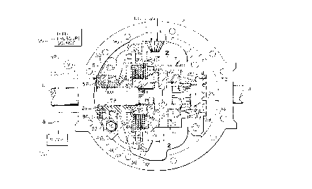
Fig. 2 is a sectional view taken along line 2-? of Fi'~. l;
Fib. 3 is a left-hand end view of the differential of Fig. 1;
Fig. 4 is and end view of the adjustable retaining ring of Fig. 1:
Figs. ~ and 6 are sectional views taken along lines 5-5 and 6-6.
respectively, of Fig. 4;
Fig. 7 is a partially assembled view of the retainer ring and lip seals as
initially provided to the customer: and
Fig. 8 is a detailed sectional view of one of the lip seals of Fig. 1.
Detailed Descriution
Referring first more particularly to Fi=. 1. the locking differential of thz
present invention includes a casing ~ that is mounted within a differential
axle
housing 4 for driving a pair of output shafts or axles 6 and 8 from drive
shaft 10
via drive pinion 1 l, rin~~ gear 12. casing 2. pinion shaft 1 ~, pinions 16.
and side
gears 18 and 20 splined to the output shafts 6 and 8. respectively. The casing
2 is
hollow and includes a pair of tubular end portions 2a and 2b that are
rotatablv

CA 02219369 1997-11-13
4
supported within opposed axle openings 22 and 24 contained in the axle
housin;~
by bearing means 26 and 28. respectively. In accordance with a characterizing
feature of the present invention, bearing means 26 is maintained in place
relative
to side gear I8 by annular adjustable retaining ring 30 that is threadably
connected
at its outer circumference with axle housing opening 22. and the other bearing
means 28 is maintained in place by a conventional lock nut 32. It will be
apparent
that when lock nut 32 is loosened relative to bearing means 28, the casing may
be
axially displaced by rotation of the adjustable retainer to effect accurate
engagement of ring gear 12 with drive pinion 11. whereupon lock nut 32 is
1G tightened to rigidly maintain the casing against axial displacement
relative to the
axle housing 4.
Side gear 18 has a tubular hub portion 18a about which is concentrically
mounted an annular friction pack assembly 36 including a stack of alternately
arranged friction plates and reaction plates that are splined for axial
displacement
I ~ relative to said side gear and a cylindrical side wall portion of the
casing chamber.
respectively. The right hand end of the friction pack assembly engages an
annular
backing plate 40, and the left hand end of the assembly is engaged by annular
spring plate 42 that is keyed for non-rotatable axial sliding displacement
relative
to the casing 2. Helical spring means 44 arranged between the friction plate
and
2Q the casin<T bias the spring plate to the left to normally cause said
friction pack
means to be in a deactivated condition. whereby the side Qear I3 is ti~eL for
rotation relative to the casing 2. In order to axially compress the friction
pack
assembly and thereby lock the side gear 18 with the casing 2. hydraulic
actuator
means are provided including an annular cylinder 46 is formed in the casing
2~ chamber end wall for receiving the annular piston 48 that reacts with the
spring
plate ~2. High pressure hydraulic fluid from source 50 is supplied (at a
pressure

CA 02219369 1997-11-13
of about 600 to 700 psi) to the working chamber of the hydraulic actuator via
manually operable valve means 52, conduit 53, retaining ring inlet opening 54.
first passage means 56 contained in the retaining ring. an annular groove 58
contained in the outer circumference of the casing end portion 2a, and a
second
5 passage 60 that extends longitudinally of the casing first end portion 2a.
As best
shown in Figs. 5 and 7, the first passage 56 in the retainir..'~ ring includes
a
longitudinal first portion 56a that extends axially of the ring, and a second
portion
56b that extends radially inwardly toward groove 58. Split cast iron seal
rings 62
and 64 provide seals in the space between the casing end portion 2a and the
inner
circumference of the retaining ring on opposite sides of the groove 58. and
resilient lip seals 66 and 68 (such as Chicago Rawhide lip seals Nos. 32330
and
31135; mounted in corresponding counter bores contained in the retaining ring
30
define leakage capture chambers 70 and 72. respectively, for returning any
leaked
hydraulic fluid back to sump 76 via fourth passage 78. discharge opening 80.
and
conduit 81. Fourth passage 78 includes a longitudinally extending through bore
portion 78a. a radially outwardly directed portion 78b, and a longitudinally
extending portion 78c that communicates with outlet 80. As shown in Fig. 7.
the
remote ends of the passage portions 56b and 78b are permanently plugged by
plugs 82. and the inlet and outlet openings 54 and 80 are initially closed by
removable screw plugs 84 and 86. respectively. The free end of the bore 60
adjacent the retaining ring is permanently plugged by the plug 88. as shown in
Fig. 7.
Referring to Fig. 3. it will be seen that initially all four of the inlet and
outlet ports of the retaining ring are closed by two sets of the removable
plugs 84
and 86. whereupon after the ring Qear adjustment has been made by the
appropriate rotatable adjustment of the retaining ring 30. the most convenient

CA 02219369 1997-11-13
6
inlet and outlet plugs are removed to permit connection of the synthetic
plastic
high pressure inlet and outlet lines ~3 and 81. respectively.
For ease of manufacture. the casing 2 is sectional and includes a center
section 2c. and a pair of end sections containing the end portions 2a and 2b,
respectively. the sections being bolted together. To improve the operation and
the
life of the differential. thrust washers 90 and 92 are provided between the
side
gears and the associated casing chamber walls.
According to the advantages afforded by the present invention. the
improved hydraulic transfer system allows the hydraulic fluid to be
transferred
from outside the fixed axle housing into the rotating differential to actuate
the
friction pack assembly. The standard lip seals are used to retain and recycle
the
hydraulic fluid without contamination of the lubricating oil container within
the
axle housing. A lubrication opening 90 may be defined between the casing
center
and first end sections to permit entry of the lubricating oil from the axle
housing
1 ~ into the friction pack assembly. The use of the synthetic plastic high
pressure
tubing permits connection of the hydraulic fluid supply and return conduits
alter
the ring gear adjustment without the use of special tools or limitations
because of
port location. The built-in capture system diverts leakage of the hydraulic
fluid
from the rotary seal means back into sump. and the size of the orifice porting
may
be used to control the reaction time of lock-up. The improved design allows
for
full lock up and is caused to slip just prior to axle shaft breakage due to
torque
overload. Furthermore. the design allows for retrofit insertion into
a1,:xisting
carrier housing with minimal modification. Finally. by varying the hydraulic
pressure. this improved design can be used for a full lock up or use as a
limited
2~ torque proportional differential.

CA 02219369 2001-10-31
7
While in accordance with the Patent Statutes the preferred forms and
embodiments of the invention have been disclosed and described, it will be
apparent that changes may be made without deviatin' from the invention set
forth
in the accompanying claims.

Representative Drawing
A single figure which represents the drawing illustrating the invention.
Administrative Status

2024-08-01:As part of the Next Generation Patents (NGP) transition, the Canadian Patents Database (CPD) now contains a more detailed Event History, which replicates the Event Log of our new back-office solution.

Please note that "Inactive:" events refers to events no longer in use in our new back-office solution.

For a clearer understanding of the status of the application/patent presented on this page, the site Disclaimer , as well as the definitions for Patent , Event History , Maintenance Fee  and Payment History  should be consulted.

Event History

Description Date
Inactive: IPC deactivated 2019-01-19
Inactive: IPC removed 2018-09-28
Inactive: First IPC assigned 2018-09-28
Inactive: IPC assigned 2018-09-28
Time Limit for Reversal Expired 2014-11-13
Letter Sent 2013-11-13
Inactive: IPC expired 2012-01-01
Letter Sent 2007-10-02
Inactive: Office letter 2007-02-26
Grant by Issuance 2004-09-14
Inactive: Cover page published 2004-09-13
Pre-grant 2004-06-29
Inactive: Final fee received 2004-06-29
Notice of Allowance is Issued 2004-01-19
Letter Sent 2004-01-19
Inactive: Approved for allowance (AFA) 2003-12-03
Amendment Received - Voluntary Amendment 2001-10-31
Amendment Received - Voluntary Amendment 2001-08-24
Letter Sent 2001-08-14
Request for Examination Received 2001-07-19
Request for Examination Requirements Determined Compliant 2001-07-19
All Requirements for Examination Determined Compliant 2001-07-19
Application Published (Open to Public Inspection) 1998-06-19
Inactive: Single transfer 1998-04-16
Inactive: IPC assigned 1998-02-18
Inactive: First IPC assigned 1998-02-18
Classification Modified 1998-02-18
Filing Requirements Determined Compliant 1998-01-21
Inactive: Filing certificate - No RFE (English) 1998-01-21
Application Received - Regular National 1998-01-20
Inactive: Courtesy letter - Evidence 1997-01-22

Abandonment History

There is no abandonment history.

Maintenance Fee

The last payment was received on 2004-07-16

Note : If the full payment has not been received on or before the date indicated, a further fee may be required which may be one of the following

  • the reinstatement fee;
  • the late payment fee; or
  • additional fee to reverse deemed expiry.

Please refer to the CIPO Patent Fees web page to see all current fee amounts.

Owners on Record

Note: Records showing the ownership history in alphabetical order.

Current Owners on Record
TRACTECH INC.
Past Owners on Record
DONALD S. SOWA
VINCENT C. DETTORE
Past Owners that do not appear in the "Owners on Record" listing will appear in other documentation within the application.
Documents

To view selected files, please enter reCAPTCHA code :


To view images, click a link in the Document Description column. To download the documents, select one or more checkboxes in the first column and then click the "Download Selected in PDF format (Zip Archive)" or the "Download Selected as Single PDF" button.

List of published and non-published patent-specific documents on the CPD .

If you have any difficulty accessing content, you can call the Client Service Centre at 1-866-997-1936 or send them an e-mail at CIPO Client Service Centre.


Document
Description 
Date
(yyyy-mm-dd) 
Number of pages   Size of Image (KB) 
Representative drawing 1998-06-17 1 21
Description 1997-11-13 6 251
Abstract 1997-11-13 1 22
Claims 1997-11-13 5 155
Drawings 1997-11-13 4 143
Description 2001-10-31 7 262
Claims 2001-10-31 4 155
Cover Page 1998-06-17 1 68
Cover Page 2004-08-12 1 57
Filing Certificate (English) 1998-01-21 1 165
Courtesy - Certificate of registration (related document(s)) 1998-06-12 1 116
Reminder of maintenance fee due 1999-07-14 1 112
Acknowledgement of Request for Examination 2001-08-14 1 194
Commissioner's Notice - Application Found Allowable 2004-01-19 1 161
Maintenance Fee Notice 2013-12-27 1 170
Prosecution correspondence 1998-03-17 1 20
Correspondence 1998-01-22 1 29
Correspondence 2004-06-29 1 26
Fees 2006-11-06 2 59
Correspondence 2007-02-27 1 28
Correspondence 2007-10-02 1 16
Correspondence 2007-09-13 1 29