Language selection

Search

Patent 2219474 Summary

Third-party information liability

Some of the information on this Web page has been provided by external sources. The Government of Canada is not responsible for the accuracy, reliability or currency of the information supplied by external sources. Users wishing to rely upon this information should consult directly with the source of the information. Content provided by external sources is not subject to official languages, privacy and accessibility requirements.

Claims and Abstract availability

Any discrepancies in the text and image of the Claims and Abstract are due to differing posting times. Text of the Claims and Abstract are posted:

  • At the time the application is open to public inspection;
  • At the time of issue of the patent (grant).
(12) Patent Application: (11) CA 2219474
(54) English Title: ELECTRONIC MOISTURE-METER WITH ALARM
(54) French Title: HUMIDIMETRE ELECTRONIQUE A ALARME
Status: Deemed Abandoned and Beyond the Period of Reinstatement - Pending Response to Notice of Disregarded Communication
Bibliographic Data
Abstracts

English Abstract


The invention consists of a portable instrument, of a very high accuracy,
which measures the soil moisture and which can be calibrated (gauged) for the
use in the most different conditions, in function of necessities.
It is a multifunctional gauge of a compact construction very well adapted
to the purpose it was conceived for.
In order to measure the soil moisture, the gauge uses the proportionality
between the soil humidity contents and its electric conductivity. The
information is displayed by a series of LED-s. In contrast with the use of a
needled pointer, this mode of displaying gives a great endurance to the gauge.
When it is switched to the ~ALARM~ mode of functioning, the gauge detects
any decrease of the soil moisture level under a preset threshold, depending on
the type of plant signaling either optically or acoustically, at choice.
The gauge uses a measuring probe of an original conception, made of
conducting tracks specially conceived for this measurement.


Claims

Note: Claims are shown in the official language in which they were submitted.

CLAIMS
1. The use of a probe made of printed circuit boards.
2. The use of a probe as explained at point 1 with conducting tracks (drawn in
a specific form) as a moisture sensor.
3. The probe described in point 1 and 2 of the Claims is detachable being
connected to the gauge by a connector.
4. The probes described in the above-mentioned claims (1, 2, 3) have different
sizes.
5. The construction of a probe in function of the plant-pot size.
6. The selection of the plant type done by means of the switch S1.
7. Selection of an alarm threshold by using a switch (S1).
8. The display of the soil moisture (by LED-s) at request by pushing a button.
9. The soil moisture is displayed by means of a series of LED-s suggestively
colored: yellow for dry soil, green for normal humidity and red when the soil
contents water in excess.
10. The achievement of an alarm in case of low moisture content of the soil.
The alarm is automatically released when the moisture-meter detects the
inferior limit of accepted moisture content. This threshold limit can be
selected by the switch S1.
11. The alarm can be launched by either optical or acoustical signals, at choice,
signaling the decrease of the soil moisture content under a preset
threshold.
12. The use of the piezoelectric sensor for the acoustic alarm and the LED for
the optical alarm.
13. The construction of a moisture-meter using the proportionality relation
between the soil humidity and its electrical conductivity.

Description

Note: Descriptions are shown in the official language in which they were submitted.


CA 022l9474 l997-l2-24
Detailed descrip~ion
The functioning mad~ of the Al~rm C~rcuit
The soil conductivity is measure~ between termina~s 1 and ~ of the
measu-rin~ et~e~rode ~Fig. 4).
The alarm cireuit compnses ~wo integrat~d eircliits of LM 555 ~ype,
transistors Ql, Q2. a ~ and the alferent passiYe components.
The t~ase of the dar~ington transistor is potarized ~y Resistors Rl and R2 and
also by the soil resistor measured between electrodes 1 and 2, noted Rl 2 This
one is varying in function of the soil wetness. The sensitivity of the input
buffer can be adjusted by the switch S1 connected to resisto~s Rl and R2: if thevalue of R~ 2 increases over a certain threshold, selected by 5" the darlington
transistor ~Q1~Q2) starts condueting and its cottector current is ctosed ~y
resistors R3, R ,. ~he v~ttage ~merginy at the terminals of resistor R3 connected
between the base ~8) and em~tter ~E~ an~ transistor ~, opens this transistor
which is feeding the integrated circuit C11 - operating as a timer - by resistorR7.
The integrated ~ircuit Ct1 has the pin t conneeted to the m~ss, pin 2
connected to pin 6 and to ~he mass by capaeitor Cl. Between pins 6 and 7 i t i ~ptared the resistor Rs which, together with resistor R6 connected between pins
7 and 3, determine the oscillation ~1equei7cy and ~he report pulseJpause of th
output vott~ge picked up by pin 3. This vottage is used to controt, l~y resistorRBI the openin~ of transistor ~, whi~h has in collector, as a charge the LED 5
s~ries-connected to resistor R, l, wltich is connected to tlle mass. T~is one w i I t
start blinking when the soil l~ecomes too dry.
The second integrate-d circuit of ~ype LM S55 use~ as soun~ generator for
the acoustic alarm is fed by switch S2. Its osciilation fr~quency is determined
by resistor Rg ~connect~ between pin 7 of the integrated circuit and its
feeding source), resistor Rto (connected between pins 7 and 6 of the integrated
circuit) and capacitor C2 ~connected between pins 2 with 6 and the mass):
fau~o = 1 ~ 2000Hz
To the outp~t of the sound generator made up ~y this integrated circuit ~pin
3) is connected an acoustic sensor, a piezoelectric sensor.

CA 02219474 1997-12-24
~ he s~and-by consumption v~ the alarm buffer is very reduced ~approx. 4 ~A)
determined only by ~he polarization resistançe of the base of Q" 0~ transistors
done by resistors R1, Rz and switch S1. When the alarm is launched, all the other
components will be fed by the electronic switch made with transistor Q~,
The very reduced current contained between the measurement electrodes 1
and Z slackens down the corrosion.
It is to note that;
R 1. 2 = p * ~
where p is in function of the soil moisture
and
e
2 s is given by the geometry of the measurement probe
~L
The functionn~ng mode o~ theMo~sture-Meter
The moisture-meter measures the soil moisture using the proportionality
relation between the moisture of the soil and its electric conductivity
measured ~etween electrodes ~ and 3 of the measurement probe. The moisture
content of the soil is indicated by 4 L~D-s (3 green ones indicating the normal
moisture content and a red one ~ndic~ting an excessive soil moisture~.
The moisture-meter is fed by S3 knob only when we want to effectuate the
humidity reading. This way we diminish both the battery current consumption
and the corrosion of the measurement probe, The integrated circuit LM 339
~quad comparator~ controls the 4 LE~ connected ~y res~stors R~s~ P~20, R21~ R22
to the 9V voltage of the battery.
The "t"lnpUts of ~he 4 comparators are all together connected to ele~trode
3 of the measurement probe.

CA 022l9474 l997-l2-24
Th~ YQ!t~Qe~+ = ~ 3f~1Z* ~-~G
We hal,re c~?oserl as ~hresh~lds:
R1,3 t ~K 50K t ~K 2K
-> v~ 4;5V ~V Q ~V Q,175
Green Red
The ~ nputs of the omparators ~re connected to the eference Yo~tages
obtained by the ch~n~ ~f r~s~o~ R13, ~14~ R~ 16~ R17~ R18 ~S ~ WS- pin 1
between R, 3 and R, 4, pin 8 between R14 and R, ~;, pin 4 between R, ~ and R, 6 and pin
6 between Rl6 ~nd R17. The ~uad c~n~,~al~tor is ~ed by pin 3 only w~en pressing
~3 ~utton during the measuremen~ process.
The pin 1~ o~ th~ inte~rat~ circ~it ~t 33~ is co~ecte~ to ~c m~ss, ~n~
the csmparatorsl outputs ~p}ns 1, Z~ 14~ 13~ are connect~d res~ectively to
LE0-s 4, 3, ~, ~ whic~ in~cat~ m~ist~fr~ c~nt~nt o~ ~h~ SOlt~
~s~
I max = ~U~UA ~ ~ r r/ Rl ~ = p * S = ~l 2 ~l le tn thP nr~be s
~ring the ~~ $ ' ' 2 ~ symmatric ~onstruc;ion.
me~suremPnt ~ Consequentiy, the posi~ion in which ~hé probe
~when S~ is ~ ~s oonneeted to ~he e~nneetor has no
pressed3 i ~ impor~ance. We may use v~riou~ ~ne~ure!nent
~.CY probes of different iengths on condition to
respect the report s by mean~ ~f which the moi~ture-meter has been
standard~ze~. -

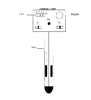
Representative Drawing
A single figure which represents the drawing illustrating the invention.
Administrative Status

2024-08-01:As part of the Next Generation Patents (NGP) transition, the Canadian Patents Database (CPD) now contains a more detailed Event History, which replicates the Event Log of our new back-office solution.

Please note that "Inactive:" events refers to events no longer in use in our new back-office solution.

For a clearer understanding of the status of the application/patent presented on this page, the site Disclaimer , as well as the definitions for Patent , Event History , Maintenance Fee  and Payment History  should be consulted.

Event History

Description Date
Inactive: IPC from MCD 2006-03-12
Inactive: Office letter 2000-07-24
Application Not Reinstated by Deadline 2000-07-20
Inactive: Dead - Application incomplete 2000-07-20
Deemed Abandoned - Failure to Respond to Maintenance Fee Notice 1999-12-24
Inactive: Cover page published 1999-07-21
Deemed Abandoned - Failure to Respond to Notice Requiring a Translation 1999-07-20
Application Published (Open to Public Inspection) 1999-06-24
Inactive: Incomplete 1999-04-20
Inactive: IPC assigned 1998-02-05
Classification Modified 1998-02-05
Inactive: First IPC assigned 1998-02-05
Inactive: Filing certificate - No RFE (English) 1998-01-22
Application Received - Regular National 1998-01-21

Abandonment History

Abandonment Date Reason Reinstatement Date
1999-12-24
1999-07-20

Fee History

Fee Type Anniversary Year Due Date Paid Date
Application fee - small 1997-12-24
Owners on Record

Note: Records showing the ownership history in alphabetical order.

Current Owners on Record
MAXIM BORCUTI
Past Owners on Record
None
Past Owners that do not appear in the "Owners on Record" listing will appear in other documentation within the application.
Documents

To view selected files, please enter reCAPTCHA code :


To view images, click a link in the Document Description column (Temporarily unavailable). To download the documents, select one or more checkboxes in the first column and then click the "Download Selected in PDF format (Zip Archive)" or the "Download Selected as Single PDF" button.

List of published and non-published patent-specific documents on the CPD .

If you have any difficulty accessing content, you can call the Client Service Centre at 1-866-997-1936 or send them an e-mail at CIPO Client Service Centre.

({010=All Documents, 020=As Filed, 030=As Open to Public Inspection, 040=At Issuance, 050=Examination, 060=Incoming Correspondence, 070=Miscellaneous, 080=Outgoing Correspondence, 090=Payment})


Document
Description 
Date
(yyyy-mm-dd) 
Number of pages   Size of Image (KB) 
Abstract 1997-12-23 1 36
Description 1997-12-23 3 141
Claims 1997-12-23 1 40
Drawings 1997-12-23 4 43
Representative drawing 1999-07-15 1 3
Filing Certificate (English) 1998-01-21 1 165
Notice: Maintenance Fee Reminder 1999-09-26 1 130
Courtesy - Abandonment Letter (incomplete) 1999-08-09 1 172
Courtesy - Abandonment Letter (Maintenance Fee) 2000-01-23 1 185
Second Notice: Maintenance Fee Reminder 2000-06-27 1 117
Correspondence 1999-04-14 2 11
Correspondence 1998-01-21 1 28
Correspondence 2000-07-23 2 55