Note: Descriptions are shown in the official language in which they were submitted.
CA 02219590 1997-10-29
METHOD AND APPARATUS FOR APPLYING
A DECORATION TO AN ARTICLE
BACKGROUND OF THE INVENTION
1. Field of the Invention
The invention relates to a method and apparatus
for applying a decoration to an article whereby the
decoration is arranged on the surface of a liquid ar_d
extended and/or condensed according to the shape of the
article prior to the article being immersed into the liquid
to transfer the decoration onto the article.
2. Background of the Prior Art
U.S. Patent No. 4,010,057, corresponding to
German Patent No. DE-A-25 34 640, describes a method and
apparatus for applying a decoration to an article using
hydrostatic pressure. This patent is hereby incorporated
by reference. However, this patent neither teaches nor
suggests extending or condensing the decoration so that it
better conforms to the shape of the article prior to
transferring the decoration to the article.
U.S. Patent No. 4,348,246 describes a transfer
printing technique in which the film with the decoration to
be transferred is not placed upon a layer of water but
instead is placed upon a layer of granules of such fine
grains that the decoration and the supporting granules
conform to the curved surface of the article, thereby
enhancing the contact of the decoration against the
article.
U.S. Patent No. 4,388,866 describes a transfer
printing technique in which the film with the decoration
to be transferred is placed upon a deformable layer of pins
which can be adapted to the shape of the article, thereby
enhancing the contact of the decoration against the
article.
U.S. Patent No. 4,436,571 describes a transfer
printing technique in which the article to receive a
decoration is immersed in a specific way into a flowing
liquid with the decoration floating thereupon. The article
CA 02219590 1997-10-29
is presented to the decoration in a continuous movement in
the general direction of the liquid flow along a downward
path oblique to the surface of the liquid and then along an
upward path cblia_ue to the surface of the liauid to provide
contact between the decoration and the article.
U.S. Patent No. 4,229,239 describes another
transfer printing technique in which the decoration is
prepared before the transfer by a solvent in order that it
detaches itself more easily from the supporting film.
U.S. Patent No. 4,x07,881, corresponding to DE-A-
32 19 992, describes a transfer printing technique in which
the decoration is supported on a layer of a special film
made of a hydrophilic, deformable layer which can swell by
absorption of water, and a further layer which is placed
over the hydrophilic layer and is varyingly permeable to
water so that the hydrophilic layer expands to a greater or
lesser extent.
U.S. Patent No. 4,231,829 describes another
transfer printing techniaue in which boric acid or a salt
thereof is added to a PVA film supporting the decoration on
the liquid or to the water on which the decoration floats
in order to promote the transfer process.
U.S. Patent No. 4,269,650 also describes a
transfer printing technique utilizing the addition of a
solvent in order to make the detachment of the decoration
from the supporting film easier.
The decoration (also referred to as printing
pattern) on a film which supports the decoration is applied
to a water surface and is extended (stretched) and/or
condensed (compressed) there. For this extending or
condensing of the floating supporting film with decoration,
the prior art discloses air blowers which are arranged
above the film with decoration in order to use an air flow
to extend and/or condense the decoration with the film,
i.e., extend it in specific directions according to the
shape of the article to be printed and, if appropriate,
condense it in other directions.
- 2 -
CA 02219590 1997-10-29
An object of the inventicn is to develop a method
and apparatus for transferring a decoration to an article
in such a way that the decoration may be shaped before the
decoration is transferred to the article so the decoration
better conforms to the article even when the article has a
complicated three-dimensional shape.
SUMMARY OF THE INVENTION
The apparatus of the present invention is
directed to applying a decoration to an article, in which
the decoration may or may not be attached to a supporting
film, wherein the apparatus is comprised of a tank through
which a liquid flows, a device for placing the decoration
or the decoration and supporting film onto the surface of
the liquid, a device for producing fluid flow, a device for
directing fluid flow upward from below the surface of the
liquid and against the decoration on the surface of the
liquid to selectively deform the decoration in a direction
parallel to the surface of the liquid to accommodate the
shape of the article, and means for immersing at least part
of the article into the liquid against the decoration to
transfer the decoration to the article.
The method of the present invention is directed
to applying a decoration to an article in which the
decoration floats on the surface of a liquid and the
article is immersed over the decoration at least partially
into the liquid in order to transfer the decoration onto
the article, the method comprising the steps of producing
a fluid flow below the surface of the liquid and deforming
with the fluid flow below the surface of the water the
decoration in a direction parallel to the surface of the
liquid to accommodate the shape of the article.
Nozzles are preferably provided as means for
producing flows in the liquid to deform the decoration.
The nozzles can preferably be adjusted according to choice
with regard to various parameters, such as water pressure,
the flow velocity, the mass flow rate and also in
particular the flow direction, to accomplish complete
- 3 -
CA 02219590 1997-10-29
control of the film shape and to permit as fast as possible
transfer printing. On the basis of the adjustable liauid
flow, the correspondingly shaped film moves very quickly in
the desired direction and assumes the desired shape, so
that thereafter the article to receive the decoration can
be immersed into the liquid on which the film with
decoration is floating, so that the decoration may be
transferred to the article.
The technique described can be used both for
extending and/or condensing decorations which are floating
on the surface on a correspondingly shaped supporting film
and for decorations which are floating directly (without
supporting film) on the surface of the liquid, provided
that the decoration has adequate stability.
According to a preferred embodiment of the
invention, the apparatus is provided with rollers close to
the surface of the lic_ruid, which are vertically adjustable
relative to the surface of the liquid. With such rollers;
the surface of the water can be calmed. In particular,
waves and irregular (unwanted) flows on the surface can be
prevented. The rollers typically lie just below the
surface of the water or are just touching the surface.
With the rollers, the film and the decoration can be
supported so that they slide uniformly over or with the
surf ace of the water. At least one of these rollers is
provided with a rotary drive so that the rollers can be
rotated.
The rollers can also be used to adjust the
advancing speed of the film with respect to the flow
velocity of the surface of the water. This makes it
possible to adjust the film advancing speed to be different
than the flow velocity of the surface of the water. For
example, the film advancing speed may be increased with
respect to the water velocity if, in the case of certain
articles to be printed, such an acceleration of the film
leads to Qood results. If, for example, the article to be
printed is immersed relatively quickly, a tearing of the
a -
CA 02219590 1997-10-29
film and of the decoration can be prevented by the rcllers
beir_c rotated sometahat faster and thus the film advancement
accelerated. The rollers also provide a hydrodynamic
separation of the tank into a downstream part, in which the
immersion process for transferring the decoration onto the
article is carried out, and an upstream part, in which the
film with the decoration is placed onto the surface of the
water.
According to a preferred embodiment, a plurality
of rollers is arranged one behind the other in the flow
direction and the vertical position relative to the surface
of the water and the rotation of each roller may be
adjusted independent of the other rollers.
The rollers also allow controlling of the process
in such a way that the film is utilized to the maximum.
Only as much film with decoration as is required for the
desired printing of the article need be used. The rollers
also stabilize the film against undesired disturbing
influences. The rollers are preferably provided with a
smooth surface, for example, of stainless steel.
. According to a further preferred embodiment of
the invention, the rollers are adjustable not only with
regard to their rotational speed and vertical height but
also in the horizontal direction parallel to the surface of
the water, both absolutely with respect to the tank and
relatively with respect to one another. The distance of
the rollers with respect to one another can be adjusted in
order to optimize the various effects mentioned above to
accommodate different articles.
A further preferred embodiment of the invention
provides that the feeding of the liquid into the tank takes
place through two rollers which are arranged at the inlet
of the tank. As a result, a uniform and homogeneous flow
is achieved, particularly on the surface. The position
with respect to the surface of the water and the rotational
speed of one or both rollers are preferably adjustable.
The two rollers are arranged approximately vertically one
- 5 -
CA 02219590 1997-10-29
above the other but spaced apart suffi ciently to leave a
very narrow, horizontal gap free between them. This gap
lies approximately at the level of the surface of the
water. Consequently, the flow of water into the tank, and
consequently also the flow velocity, can be controlled in
a way corresponding to the requirements of the article on
which the decoration will be applied.
According to a preferred embodiment of the
invention, at least one of the rollers may also serve to
measure the height of the water level as input to the
computer controlling the process. For example, a pressure
sensor can be used to measure the water pressure acting on
the roller. The pressure may be used to measure the height
of the water level, if the sensor on the roller is kept at
a certain height in the vertical direction.
A further preferred embodiment of the apparatus
according to the invention provides that two rollers are
arranged next to each other at the downstream end of the
tank, close to the surface of the liauid, in such a way
that film residues and/or decoration residues run over both
rollers, and the residues are isolated from the remaining
portion of the tank. These residues may be filtered,
thereby permitting a clean liquid to return to circulation
in the tank. Additionally, the gap between the rollers
permits relatively clean liquid to pass downward to return
to circulation in the tank.
BRIEF DESCRIPTION OF THE DRAWINGS
An exemplary embodiment of the invention is
described in more detail below with reference to the
drawings, in which:
Figure 1 schematically shows from the side an
apparatus for applying a decoration to an article;
Figure 2 shows a schematic of a plan view of the
apparatus according to Fig. 1;
Figure 3 shows a schematic of a side view of an
upstream section of the apparatus according to Fig. 1;
- 6 -
CA 02219590 1997-10-29
Ficure 4A schematically shows a nczzle for
producing a water flow in a variety of different
directions;
Figure 4B shows a schematic view of the range of
rotation available with each nozzle; and
Figure 5 shows a schematic view of an article to
be decorated prior to the transfer of the decoration.
DESCRIPTION OF THE PREFERRED EMBODIMENTS
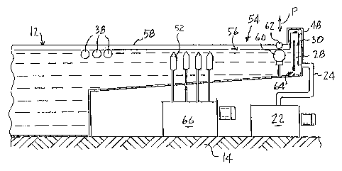
Fig. 1 shows a transfer printing apparatus. On
the right is a housing 10 in which a supporting film 50
having a series of decorations 51 on its upper side is fed
by means of rollers 82, 76, 78, 80, 18, 20 to a tank 12
filled with a liquid such as water. The decorations are
separated from one another on the supporting film 50 and
restrained relative to one another only by the supporting
film 50. The chemical and physical structure of the film
is not the subject of this invention, nor is the chemical
and physical structure of the decoration applied to the
film. Such decorations and supporting film are well known
to those skilled in the art.
The housing 10 and the water tank 12 stand on a
common foundation 14 which isolates and supports the entire
transfer printing installation in such a way that outside
mechanical disturbing influences are greatly diminished.
Film 50 with the decoration 51 is brought from
the housing 10 to the surface of the water in the tank 12
by means of a film feed 16 in the form of an obliquely
running conveyor belt. The conveyor belt of the film feed
16 runs over rollers 18, 20.
In Fig. 1, and in each of the Figures 1-3, the
water f lows from right to left through the tank 12. For
this purpose, a pump 22 is provided which maintains water
circulation. A supply line 24 leads from the pump 22 into
a cavity 30. The cavity 30 is filled and water is pumped
over a dam wall 28 at a height which lies above the surface
of the water in the tank 12 to water inflow 26.
_ 7 _
CA 02219590 1997-10-29
The flow path of the water is shown in more
detail by arrow 48 in Fig. 3, and the introdLCtior_ of the
water into the tank 12 is described more precisely further
below.
The film 50 and the decoration 51 are presented
to the tank 12 by means of the film feed 16 which is
advanced in the direction of the water flow. Film feed 16
is comprised of a rotating conveyor belt which runs over
rollers 18, 20. Guide belts 32, 32a are laterally spaced
and run over rollers 34, 36, which extend across the width
of the tank 12.
The process of transferring the decoration to an
article is well known by those skilled in the art and is
discussed in the prior art patents previously identified.
Such a transfer is typically done by immersing the article
against a decoration floating on the surface of a liquid.
Means for immersing an article 40 into the liquid against
the decoration 51 to transfer the decoration to the article
40 are also well known by those skilled in the art and are
discussed in prior art patents previously identified. As
an example, United States Patent No. 4,010,057 discloses a
means for immersing an article comprised of a liquid
pressure actuating cylinder which lifts and lowers an arm.
The arm extends over the liquid on which the decoration
floats. At the end of the arm is a holding section used to
hold the article. The article then may be lowered into or
lifted from the liquid by the activation or deactivation of
the actuating cylinder.
The holding section can be designed in accordance
with the shape of the article. As an example, in the event
the article is box-like and has interior walls, the holding
section may be made of arms which pivot outwardly to press
against and engage the interior walls of the article.
Returning to Figure 1, the article 40 to receive
the decoration 51 is immersed from above into the water in
the tank 12 at a location marked by an arrow 41. At the
same time, the film with the decoration is floating on the
- 8 -
CA 02219590 1997-10-29
surface of the water, approximately at the height of the
lateral guide belts 32, 32a. The article 40 is immersed
over the deceraticn 51 such that the hydrostatic pressure
on the floating decoration 51 urges the decoration 51
against the article 40. Fig. 5 schematically shows the
immersion of the article 40 into the liquid on which the
supporting film 50 and the decoration 51 are floating.
During this immersion, the decoration 51 is subjected to
hydrostatic pressure from the liquid which urges the
floating decoration 51 to conform three-dimensionally
around the article 40 and adheres to the article 40. By
this technique, it is possible to print true to scale onto
complicated three-dimensional articles. In this process,
there remain in the flowing water residues of the film and
of the decoration which cannot be further used. For
example, in the prior art a film of PVA (polyvinyl
alcohol), which is more or less soluble in water, is used.
The roller 36, in addition to supporting the
guide belts 32, 32a, has an additional function in
conjunction with roller 42, which is located downstream of
roller 36 and extends across the entire width of the tank
12. Rollers 36 and 42 promote separation of film residues
and decoration residues. These rollers are arranged such
that a narrow gap 44 is left free between them. Film
residues and decoration residues transported over the
roller 36 reach the roller 42 and are transported further
by the rotation of roller 42. These residues reach a
filter 46 which separates the film residues and decoration
residues from the water and discharges clean water into the
30' lower region of the tank 12 and back to the pump 22. Also,
through the narrow gap 44 between the rollers 36 and 42,
relatively clean water returns into lower regions of the
tank 12.
Figures 2 and 3 show schematic drawings of the
apparatus from above and from the side. Fig. 3 illustrates
details of the introduction of water into the tank. As
already stated above with reference to Fig. 1, the water
_ g _
CA 02219590 1997-10-29
rises in the cavity 30 over the dam wall 28 and falls from
there into the tank 12. Provided underneath the dam wall
28 is an opening 6a (Fig. 3) through which excess water can
enter directly into the tank 12.
In Fig. 3, the path of the water over the dam
wall 28 is diagrammatically represented by arrow 48 and the
associated solid line. The water is fed through an
intermediate space between two rotating rollers 60, 62 into
the tank. The two rollers 60, 62 are arranged vertically
one above the other and are adjustable vertically in the
direction of an arrow P. While preferably both rollers 60,
62 have rotary drives, at least one roller, such as the
lower roller, has a rotary drive. The rotational speed of
the rollers is such that the water is transported in a
direction corresponding to an arrow 56. The arrow 56 also
marks the surface of the water in the tank 12.
In Fig. 3, the lower roller 60 thus rotates
counterclockwise and the upper roller 62 rotates clockwise.
By adjusting the rollers 60, 62 in their vertical height,
adjusting their distance from each other and adjusting the
rotational speed, the flow of the water into the tank can
be optimally controlled. For example, the distance between
the two rollers may be about 1 cm depending on the
reuuirements of the article to be printed. The distance is
used to control the rate water is introduced to the
upstream end of the tank 12. The rotational speed of the
rollers (mainly of the lower roller 60) can be used to
influence the flow velocity at the surface indicated by the
arrow 56 in the tank 12. The rollers 60, 62 are preferably
made with a smooth surface, for example, of stainless
steel.
The level of the water in the tank 12 is
continuously measured by means of a sensor (not shown).
Any of a number of commercially available sensors is
suitable. This information about water level is passed to
a computer, which controls all the adjustable components
and evaluates this information correspondingly. For
- 10 -
CA 02219590 1997-10-29
example, if waves occur, the computer can alter the
rotation, position and distance apart of the rollers 60, 62
in order to prevent the occurrence of waves and to keep the
surface of the water calm.
It is possible to deform by extending or
condensing the film 50 with the decoration 51 printed on it
after the film 50 is introduced to the water of the tank
12. The film 50, with the decoration printed on it, is
transported down from the film feed 16 and reaches the
surface of the water in the tank 12 approximately at a
point 54. There it floats on the surface and is carried
along by the flow.
Arranged below the surface of the water in the
tank 12 is a plurality of nozzles 52 capable of directing
the water to flow in various directions. Fig. 4A shows a
typical nozzle 52 schematically in an enlarged
representation. Each nozzle may be spatially positioned,
according to choice, for changing the flow directions,
depending on the desired shaping of the film in a way
corresponding to the article to receive the decoration.
Fig. 4B shows schematically the adjustability of the flow
direction by means of a nozzle 52 pivotable about a base
52a and having a discharge orifice 52b. An axis 70 defines
the flow direction of the nozzle 52, which is adjustable in
an inclined manner with respect to the surface of the water
~as indicated by arrow 56.
According to the plan view of Fig. 2, an array of
nozzles, for example, an array of twelve nozzles in a 3 x 4
arrangement, is positioned in such a way that desired flows
can be produced virtually at any point of the surface of
the water indicated by arrow 56. The nozzles 52 discharge
a water flow upwards or obliquely upwards in order to
extend or condense the stretchable and compressible film.
In the region 50a (Fig. 2), the film 50 floating on the
surf ace of the water indicated by arrow 56 in the tank is
thus extended or condensed in a way corresponding to the
reauirements of the article to be printed (not shown). It
- 11 -
CA 02219590 1997-10-29
is also ncssible to orient the nozzles 52 so that water
flow is directed to extend one or more portions of the
decoration while condensing one or more other portions of
the decoration.
In Fig. 1, a pump 66. used to drive the water
through the nozzles 52 is represented. Above the pump four
arrows, which symbolize the individual nozzles 52, are
shown. It should be understood that while a 3 x 4 array of
nozzles has been disclosed, any number of nozzle patterns
may be suitable to extend or condense the film 50 and the
associated decoration 51 and the invention should not be
limited to this one specific arrangement.
In a region 50b, the film 50 with the decoration
51 has reached its desired (extended or condensed) shape
and is transported downstream over a plurality of rollers
38. The rollers 38 are adjustable in their height in such
a way that each of their upper edges is approximately flush
with the surface of the water indicated by arrow 56. The
rollers 38 are preferably formed with a smooth surface, for
example, of stainless steel. Preferably, each of the
rollers 38 has a rotary drive and may be adjusted for
rotational speed and height. The rollers 38 can be used to
calm the surface of the water, in particular downstream (to
the left) and also to stabilize the advancement of the
film. If need be (depending on the article receiving the
decoration), the rollers 38 can also be used to adjust the
advancing speed,of the film to be faster or slower than the
flow velocity of the water. The former is advisable in
particular whenever the article to be printed has to be
immersed very deeply into the tank or when the article has
to be immersed quickly. Increasing the advancing speed of
the film relative to the flow velocity of the water then
prevents a tearing of the film.
In the case of the embodiment illustrated, three
rollers 38 are provided which are cylindrical and
independently with respect to one another adjustable for
vertical position, rotational speed and horizontal
- 12 -
CA 02219590 1997-10-29
distance. The rollers 38 can be used to control the
feeding in of the decorative film 50 as it progresses
downstream.
Lvhile the discussion has been directed to a
S supporting film 50 with a decoration 51 upon it, it is
possible, if the decoration 51 has enough stability and
strength, for the decoration 51 to be processed and
transferred to an article without the need for a supporting
film 50. However, in this case there would be a continuous
strip of decorations that must be separated to accommodate
each article.
Although the invention has been described with
reference to a specific embodiment, numerous modifications
are possible without departing from the invention, and it
is desirable to cover all modifications falling within the
spirit and scope of this invention.
- 13 -