Note: Descriptions are shown in the official language in which they were submitted.
CA 02219671 1997-10-28
MODU~E ATTACEABLR TO FACADES OF BUI~DINGS FOR EVACUATING
PEOPLE
OBJECT OF T~I13 lNV ~.~ lON
The present invention refers to a module attachable to
facades or suitable places of buildings for evacuating
people, with characteristics of those from which functional
and even structural advantages are derived from the module
in question.
A fundamental object of the invention is that when the
module unfolds, the two parts that comprise it, swing
simultaneously towards the horizontal position, based on a
special transmission element provided for between said two
parts.
~Rq~ouN~ OF T~E INVENTION
Spanish patent application no. 9201298 claims a module
attachable to facades of buildings for evacuating people, a
module which is comprised of two parts hinged together, in
such a way that one of them is, in turn, hinged, by means
of its top edge, to the corresponding facade of the
building, in such a way that in a folded position the part
hinged or jointed to the facade remains attached to it,
while the second part remains attached to the other part
and hinged to it, in said folded position, by means of the
corresponding bottom edge.
Now then, the constituent parts of the module comprise
a series of elements such as a foldable ladder, some
handrails, a fastening tie, and other components so that in
the folded position people can be evacuated from one flat
to another along the outside of the facade, logically
through one of the windows or openings made for this
purpose, in correspondence with which the module itself
will be located.
The part of the module that is hinged to the facade or
suitable place, once the anchoring element or device that
fastens it in the folded position has been released, by
CA 02219671 1997-10-28
gravity swings and adapts a horizontal position, while for
the other part, being hinged to the previous part, it is
necessary that an element or cable pulls it to likewise
place it in a horizontal position, forming between both
parts a horizontal surface whereon is provided a support
platform for people and a hollow space or area through
which they will have access to the module right below, by
means of the ladder that forms part of the module.
DESCRIPTION OF TEE lNVI .llON
The module described in Spanish patent application no.
9201298 referred to in the above section, has been improved
in certain aspects thereof, the main improvement consists
of the inclusion of a transmission device of the swinging
motion from the first part or internal part of the module
in the folding of the module, whose transmission of
rotation or swinging is done directly on the second part or
external part, so that in the unfolding both parts take on
themselves a horizontal position without any additional
elements.
This improvement prevents the need to use, if one
considers it to be convenient, additional means such as
motors, hydraulic or pneumatic pressure accumulators,
springs, or any other type of harnessing or accumulating of
force or energy extrinsic to the force of gravity itself,
in order to achieve the swinging of the external part
towards the horizontal position in the unfolding of the
module.
The invention basically consists of a module
attachable to facades of buildings for evacuating people,
comprised of:
an internal part with a proximal end and a distal end,
said internal part being provided with first hinged linking
means in order to be linked and fastened in a jointed
manner to the facade (or to an equivalent structure) of a
building, in such a way that said internal part can swing
CA 02219671 1997-10-28
between a first substantially vertical position and a
second substantially horizontal positioni
an external part with a proximal end and a distal end,
the proximal end of said external part being linked to the
distal end of the internal part by means of second hinged
linking means, in such a way that the external part may be
rotated from a first position in which said external part
is substantially folded over said internal part, to a
second position in which said external part is unfolded
with regard to said internal part, adopting a substantially
horizontal position, as an extension of the internal part;
at least a foldable ladder (and, optionally, other
accessories such as safety barriers, etc.), housed between
said internal part and said external part when said
internal part and said external part are in said first
position; and
a transmission device for the transmission of a
swinging motion of the internal part to the external part.
This transmissions device includes a rotating part
fixedly hinged to the external part, and a first winding
and unwinding tie, the rotating part and the first tie
being arranged in such a way that when the internal part
swings from the first position towards the second position,
the first tie produces a rotation of said rotating part
giving rise to a swinging of the external part around the
second hinged linking means. In this way, when the
internal part swings from its first substantially vertical
position towards it second substantially horizontal
position, the external part is swung from first
substantially vertical position towards its second
substantially horizontal position.
Preferably, the second hinged linking means are
connected to the bottom edges of the corresponding ends of
the external and internal parts. The rotating part is
preferably connected to the area of the second hinged
CA 02219671 1997-10-28
linklng means, for example, with the bottom edge of the
proximal end of the external part.
The first tie may include means so that it may be
coupled to a facade of a building or to a fixed point
connected to said facade.
The rotating part may be formed by a body with at
least one curved portion, for example, by a pulley or
toothed wheel, On the other hand, the first tie may be or
may include a belt or a chain.
Hereinafter, to provide a better understanding of this
specification and forming an integral part of the same,
some figures wherein the object of the invention has been
represented in an illustrative and non-restrictive manner,
are-attached hereto.
BRIBF DESCRIPTION OF THE FIGURES
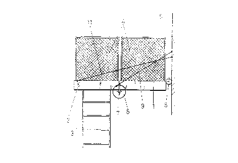
Figure 1 shows a side raised schematic view of the
module in accordance with the invention, which is provided
with, in the area corresponding to the joint between both
parts of the module, a device that transmits the rotary
force of the internal part from the module to the external
part, in order to achieve in the unfolding of the module
the simultaneous horizontality of both parts.
Figure 2 shows a side raised view of the module in its
unfolded position, remaining placed horizontally and where
one can see the ladder as well as the handrail or guardrail
that form part of the module.
DETAILED DESCRIPTION OF PREFERRED EMBODIMENTS O~ THE
lNVL~.~ lON
In view of figures 1 and 2, one can see how the module
of the invention provided for to be attachable to facades
or suitable places of buildings for evacuating people, is
comprised of two parts (1, 2), one internal part (1) and
another external part (2), which in a folded position as
represented in figure 1, house a series of accessories
necessary for safe and effective evacuation, such as a
CA 02219671 1997-10-28
ladder (3), some guardrails, handrails or side safety
barriers (4), as represented in the unfolded position of
figure 2, or other accessories.
In any case, the internal part (1) of the module is
linked to the corresponding facade (5) or suitable place of
the building by means of a first hinged linking means (6)
that allows the internal part (1) to be attached to the
facade or suitable place as shown in figure 1, in the
folded position, or else swing and remain in the horizontal
position, as shown in figure 2.
As one can see, the internal part (1) is linked to the
facade (5~ or suitable place by means of the top edge of
the proximal end thereof (1'), as clearly shown in the
figures, while the second hinged linking means (7) between
the external part (2) and the internal part (1) is mounted
in correspondence with the bottom edge (la) of the distal
end (1'') of the internal part (1) and with the bottom edge
(2a) of the proximal end (2~) of the external part (2). In
the unfolded position, represented in figure 2, the second
hinged linking means (7) remains between said external (2)
and internal (1) parts, but in correspondence with the
bottom area, for the purpose of preventing that in that
unfolded position the external part (2) can swing upward
with regard to the internal part (1).
Now then, a rotating piece or part (8) integral to the
external part (2), in correspondence with the hinging area
of the second hinged linking means (7), in such a way that
this rotating part (8) is connected by means of a first tie
(9) to a fixed point (10), that may be of the facade itself
or of any fixed element foreign to three module itself.
This first tie (9) is partially wound over the rotating
part (8), in the folded position, as shown in figure 1,
while when the unfolding takes place, at the moment when
the internal part (1) begins to swing outward, the first
tie (9) will pull the rotating part (8) making it turn and
CA 02219671 1997-10-28
therefore making the external part (2) swing in the
opposite direction. That is to say, that while in the
unfolding the internal part ~1) turns counterclockwise,
according to the arrow provided around the first hinged
linking means (6~, the external part (2), as it is pulled
by the rotating part (8), turns clockwise, as also shown by
the arrow represented on the top part of the rotating part
(8).
Obviously, this rotating part (8) when the internal
part (1) begins to unfold makes the external part (2) start
the corresponding swing so that both parts (1, 2) lay
simultaneously horizontally, with the particularity, that
maintaining the horizontality is achieved by means of a
seco~d tie (11) or other suitable means anchored between a
point close to the distal end (2'l) of the external part
(2) and a point of the facade (5). As can be seen in
figure 2, the first tie (9) becomes longer as a result of
its unwinding with regard to the rotating part (8), winding
over it in the folded position of the module, just as it is
shown in figure 1.
The rotating part (8) is formed by a body with a
totally or partially curved, toothed or untoothed, profile
which may be comprised of a pulley, a toothed wheel, etc.,
while the first tie (9) will be a totally or partially
flexible element, and will be comprised of or include a
cable, belt, chain, etc., logically depending on the
constitution of the rotating part (8) and in any case with
the necessary rigid parts, if there were any, as well as
the necessary elements of adjustment, anchorage and
transmission of movements.
This rotating part (8) makes it possible not to have
to use additional means for unfolding and to achieve the
horizontality of the external part (2), although it is not
excluded that in certain cases, due to the needs of
assembly or characteristics of the building, additional
CA 02219671 1997-10-28
elements such as motors, hydraulic or pneumatic pressure
accumulators, elastic elements or any other device for
harnessing or accumulating force or energy extrinsic to the
force of gravity itself, be required.