Language selection

Search

Patent 2219939 Summary

Third-party information liability

Some of the information on this Web page has been provided by external sources. The Government of Canada is not responsible for the accuracy, reliability or currency of the information supplied by external sources. Users wishing to rely upon this information should consult directly with the source of the information. Content provided by external sources is not subject to official languages, privacy and accessibility requirements.

Claims and Abstract availability

Any discrepancies in the text and image of the Claims and Abstract are due to differing posting times. Text of the Claims and Abstract are posted:

  • At the time the application is open to public inspection;
  • At the time of issue of the patent (grant).
(12) Patent Application: (11) CA 2219939
(54) English Title: STEERING COLUMN CLAMPING MECHANISM
(54) French Title: MECANISME DE VERROUILLAGE POUR COLONNE DE DIRECTION
Status: Deemed Abandoned and Beyond the Period of Reinstatement - Pending Response to Notice of Disregarded Communication
Bibliographic Data
(51) International Patent Classification (IPC):
  • B62D 1/18 (2006.01)
  • B62D 1/184 (2006.01)
  • F16B 2/06 (2006.01)
(72) Inventors :
  • BOBBITT, JOHN THOMAS III (United States of America)
  • BAKER, STEPHEN JOHN (United Kingdom)
(73) Owners :
  • NASTECH EUROPE LIMITED
(71) Applicants :
  • NASTECH EUROPE LIMITED (United Kingdom)
(74) Agent: SWABEY OGILVY RENAULT
(74) Associate agent:
(45) Issued:
(86) PCT Filing Date: 1996-05-15
(87) Open to Public Inspection: 1996-11-21
Availability of licence: N/A
Dedicated to the Public: N/A
(25) Language of filing: English

Patent Cooperation Treaty (PCT): Yes
(86) PCT Filing Number: PCT/GB1996/001163
(87) International Publication Number: WO 1996036520
(85) National Entry: 1997-10-30

(30) Application Priority Data:
Application No. Country/Territory Date
9510038.4 (United Kingdom) 1995-05-18

Abstracts

English Abstract


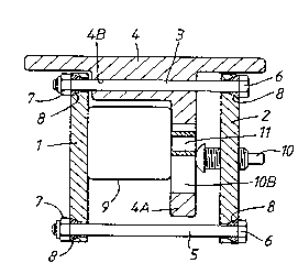
A steering column clamping mechanism has bolt links (3, 5) interconnecting
substantially parallel spaced-apart plates (1, 2) which basically form a
rectangle and are so linked one to another that the rectangle can lozenge to a
parallelogram. One of the connecting bolts (3) is mounted in a bracket (4)
fixed to a chassis of a vehicle, the bracket (4) having a depending reaction
plate (4A) against which an actuating member (10) can be urged to push the
plate member (2) away from the reaction member (4A). Through the linkage, this
causes the other plate member (1) to compress onto a steering column tube
member (9) to clamp it between that plate (1) and the opposite side of the
reaction plate (4A).


French Abstract

Un mécanisme de verrouillage pour colonne de direction comprend des liaisons à boulons (3, 5) reliant des plaques sensiblement parallèles (1, 2) et disposées à une certaine distance l'une de l'autre. Les plaques sont sensiblement rectangulaires et sont liées ensemble de sorte que le rectangle puisse se déformer en losange et prendre la forme d'un parallélogramme. Un des boulons de liaison (3) est monté dans un support (4) fixé au châssis d'un véhicule, ce support (4) comprenant une plaque de réaction descendante (4A) contre laquelle un élément d'actionnement (10) peut être poussé pour éloigner la plaque (2) de l'élément de réaction (4A). Grâce à ce système de liaison, l'autre plaque (1) est comprimée sur une jupe (9) de la colonne de direction de sorte que cette dernière soit immobilisée entre ladite plaque (1) et le côté opposé de la plaque de réaction (4A).

Claims

Note: Claims are shown in the official language in which they were submitted.

-6-
CLAIMS:
1. A steering column clamping mechanism including a
steering column tube member (9), a bracket (4) and an
actuating member (10), characterised by two spaced apart
plate members (1, 2), a first connecting link (3) joining
said two plate members, said bracket (4) supporting said
first connecting link, a second connecting link (5) joining
said two plate members remote from said first connecting
link, a reaction plate (4A) between said two plate members
(1, 2), said steering column tube member (9) being located
between said first and second connecting links and located
between and being clampable by one of said plate members
and said reaction plate, and said actuating member (10)
being located to act to urge the other of said two plate
members and the reaction plate apart thereby to cause said
one plate member and said reaction plate to clamp said
steering column tube member.
2. A clamping mechanism according to claim 1, wherein
said reaction plate (4A) is joined to and forms part of
said bracket (4).
3. A clamping mechanism according to claim 1 or 2,
wherein said first connecting link is in the form of a bolt
member (3) passing through said bracket (4) and opposite
ends being anchored to said first and second plate members
(1, 2).
4. A clamping mechanism according to claim 1, 2 or 3,
wherein said second connecting link is a bolt member (5)
anchored at opposite ends to said first and second plate
members (1, 2), respectively.

- 7 -
5. A clamping mechanism according to any one of the
preceding claims, wherein the respective connections
between said two plate members (1, 2) and said first and
second connecting links (4, 5) are in the form of washers
(8).
6. A clamping mechanism according to claim 5, wherein the
washers are domed washers (8) set in their plate members
(1, 2).
7. A clamping mechanism according to any one of the
preceding claims, wherein, when viewed on end, said plate
members (1, 2) and their connecting links (4, 5) are
substantially in the form of a rectangle and said reaction
plate (4A) is substantially parallel, in an unclamped state
of the tube member (9), to the two plate members, which are
also substantially parallel to one another.
8. A clamping mechanism according to any one of the
preceding claims, wherein the steering column tube member
(9) in the region where it passes through the clamping
mechanism is substantially rectangular in outer section.
9. A clamping mechanism according to any one of the
preceding claims, wherein said actuating member is in the
form of a clamp bolt (10) which is threadably engaged in
said second plate member (2) to extend the clamp bolt
towards and away from said reaction plate (4A).
10. A clamping mechanism according to any one of claims 1
to 8, wherein said actuating member is a cam arrangement.
11. A clamping mechanism according to any one of the
preceding claims, wherein said actuating member is a
solenoid-operated actuating member.

- 8 -
12. A mechanism according to any one of the preceding
claims, wherein a protrusion (11) is provided on the
outside of said steering column tube member (9), which
protrusion rides in a slot (4C) provided in said reaction
plate (4A) to limit travel of the steering column tube
member.
13. A vehicle incorporating a steering column clamping
mechanism according to any one of the preceding claims.
14. A vehicle according to claim 13, wherein said bracket
is attached to a chassis of the vehicle.

Description

Note: Descriptions are shown in the official language in which they were submitted.


CA 02219939 1997-10-30
W 096/36520 PCT/GB96/01163
8TEERING COLUMN C~AMPING MECRANI5M
This invention relates to a steering column clamping
me~h~ni~m. Known steering column clamping me~h~nisms tend
to require rather close manufacturing tolerances and a
typical type can be seen in EP-A-0 242 928.
According to the present invention, there is provided a
steering column clamping ~~h~n;~m including a steering
column tube member, a bracket and an actuating member,
characterised by two spaced apart plate members, a first
connecting link joining said two plate members, said
bracket supporting said first connecting link, a second
connecting link joining said two plate - h~s remote from
said first connecting link, a reaction plate between said
two plate members, said steering column tube member
being located between said first and second connecting
links and located between and being clampable by one of
said plate h~l-5 and said reaction plate, and said
actuating member being located to act to urge the other of
said two plate ~ h~5 and the reaction plate apart thereby
to cause said one plate member and said reaction plate to
clamp said steering column tube member.
Preferably, said reaction plate is joined to and forms part
of said bracket.
Said first connecting link can be in the form of a bolt
- h~ passing through said bracket and opposite ends being
anchored to said first and s~con~ plate members.
Said second connecting link can be a bolt member anchored
at opposite ends to said first and second plate members,
respectively.

CA 02219939 1997-10-30
W O 96/36520 PCT/GB96/01163
The respective connections between said two plate members
and said first and C~c~Qr~l connecting links can be in the
form of washers. The washers can be domed washers set in
their plate -h~s.
When viewed on end, the plate members and their connecting
links can be substantially in the form of a rectangle and
the reaction plate can be substantially parallel, in an
unclamped state of the tube -lnh~ to the two plate
members, which are themselves substantially parallel to one
another. The steering column tube -r'h~ in the region
where it passes through the clamping mec-hAn;~ can also be
substantially rectangular in outer section.
The actuating member can be in the form of a clamp bolt
which is screwed in and out of the ~co~ plate member to
extend the clamp bolt towards and away from the reaction
plate.
Other possible types of actuating h~ can be a cam
arrangement. The actuating member may be a solenoid-
operated actuating - h~.
Provision can be made to limit travel of the steering
column tube member and this can be achieved by providing a
ylvL~lsion on the outside of the steering column tube
member, which ~vL~usion can ride in a slot provided in the
reaction plate.
For a better understAn~;ng of the invention and to show how
the same may be carried into effect, reference will now be
made, by way of example, to the a~ _-nying drawing, in
which:-

CA 02219939 1997-10-30
W 096/36520 PCT/GB96/01163
Figure 1 is a sectional end view of part o~ a steering
column clamping me~hAn;~m, taken on the line X-X in Figure
2, and
Figure 2 is a side view of the part of the clamping
mech~n;~m shown in Figure 1.
The drawing shows part of a steering column clamping
me~-h~ni~ including two substantially parallel, spaced
apart plate members 1, 2, a first connecting link 3 joining
the two plate members 1 and 2, a bracket 4 ~u~ Ling the
connecting link 3 and a C~ron~ co~necting link 5 joining
the two plate members 1, 2 remote from the first ro~n~cting
link 3. The bracket 4 is fixed, e.g. to the chassis of a
vehicle.
In the form shown, each connecting link 3, 5 is in the form
of a bolt, each passing through the two plate members 1 and
2 and being secured by bolt heads and nuts 6, 7,
respectively. The bolt of the connecting link 3 passes
through a bore 4B in the bracket 4.
As shown, the ~onn~ting links and plate members produce a
substantially rectangular form when viewed from the
orientation given in Figure 1. However, provision is made
at the respective ~onn~ctions between the plate h~s and
connecting links so as to allow the two plate members to
"lozenge" into a parallelogram. In other words, their
direction of parallelism can be reorientated. This is
achieved by providing domed washers 8 at each ~o~n~ction
set into the respective plate members 1, 2.
D~p~n~; ng from the bracket 4 between the plate members 1,
2 is a reaction plate 4A (forming part of the bracket 4)
and a substantially rectangular steering column tube member

CA 02219939 1997-10-30
W 096/36520 PCT/GB96/01163
9 is located between the inside of the first plate member
1 and one side of the reaction plate 4A. The steering
column tube member 9 is adjustable to allow the steering
wheel to be adjusted to a desired position by the vehicle
driver.
An actuating ~- h~t- 10, in the present embodiment being in
the form of a screw actuator, is provided to act between
the opposite side of the reaction plate 4A to the tube
member 9 and the second plate member 2.
Figure 1 illustrates the situation in the substantially
unclA -~1 state of the steering column tube h~ 9 and it
will be seen that, by screwing the actuator 10 into the
plate 2 by rotating its squared end lOA, a head lOB of the
actuator 10 will be urged to the left to bear on the
reaction plate 4A. By virtue of the provision of the
washers 8 and since the reaction plate 4A is fixed, this
will have the effect of urging the reaction plate 2 to the
right as viewed in Figure 1 away from the reaction plate 4A
and the leverage so provided will, through the connecting
links 3 and 5 and the plate h.~- 1, cause these members
and links to lozenge, t~ki ng Up any manufacturing
tolerances, and causing the plate member 1 to be drawn in
compression against the steering column tube ~ h~t- 9 to
clamp it in position.
It will be appreciated that the bore 4B through the bracket
4 through which the connecting link 3 pAcc~c should be oval
or in some other way elongate to allow for free movement of
the connecting link; this is especially true in the case
envisaged where more than two connecting links are
provided. As an example, in the present case, Figure 2
demonstrates that the bracket 4 is provided with six holes

CA 02219939 1997-10-30
W 096/36520 PCT/GB96/01163
- 5 -
or bores 4B to allow for the use of two, four or six
connecting links.
It will be appreciated that because of the point contact of
the head lOB of the clamped screw 10, the assembly is
allowed to lozenge as described and the steering column
tube member 9 is compressed between the bracket reaction
plate 4A and the plate member 1. Any out of parallel
condition of the steering column tube is compensated for by
the fact that the plate member 1 can lozenge out of
parallel to the reaction plate 4A. This lozenging effect
also helps to widen the tolerance of the bolt length and
nut position, as the plates themselves do not need to be
exactly parallel.
The reaction plate 4A is provided with a substantially
rectangular opening 4C and this accommodates a ~vLLusion
on the outside of the steering column tube 9, the
protrusion being in the form of a pin 11 with a soft
covering which rides in the rectangular op~n; ng in order to
limit steering column travel, the soft covering giving a
soft feel when reaching the end positions in the opening
4C.

Representative Drawing
A single figure which represents the drawing illustrating the invention.
Administrative Status

2024-08-01:As part of the Next Generation Patents (NGP) transition, the Canadian Patents Database (CPD) now contains a more detailed Event History, which replicates the Event Log of our new back-office solution.

Please note that "Inactive:" events refers to events no longer in use in our new back-office solution.

For a clearer understanding of the status of the application/patent presented on this page, the site Disclaimer , as well as the definitions for Patent , Event History , Maintenance Fee  and Payment History  should be consulted.

Event History

Description Date
Inactive: IPC from MCD 2006-03-12
Inactive: Dead - No reply to Office letter 2000-02-02
Application Not Reinstated by Deadline 2000-02-02
Deemed Abandoned - Failure to Respond to Maintenance Fee Notice 1999-05-17
Inactive: Status info is complete as of Log entry date 1999-03-24
Inactive: Abandoned - No reply to Office letter 1999-02-02
Classification Modified 1998-02-18
Inactive: IPC assigned 1998-02-18
Inactive: First IPC assigned 1998-02-18
Inactive: Courtesy letter - Evidence 1998-02-03
Inactive: Notice - National entry - No RFE 1998-01-28
Application Received - PCT 1998-01-26
Application Published (Open to Public Inspection) 1996-11-21

Abandonment History

Abandonment Date Reason Reinstatement Date
1999-05-17

Maintenance Fee

The last payment was received on 1997-10-30

Note : If the full payment has not been received on or before the date indicated, a further fee may be required which may be one of the following

  • the reinstatement fee;
  • the late payment fee; or
  • additional fee to reverse deemed expiry.

Please refer to the CIPO Patent Fees web page to see all current fee amounts.

Fee History

Fee Type Anniversary Year Due Date Paid Date
Basic national fee - standard 1997-10-30
MF (application, 2nd anniv.) - standard 02 1998-05-15 1997-10-30
Owners on Record

Note: Records showing the ownership history in alphabetical order.

Current Owners on Record
NASTECH EUROPE LIMITED
Past Owners on Record
JOHN THOMAS III BOBBITT
STEPHEN JOHN BAKER
Past Owners that do not appear in the "Owners on Record" listing will appear in other documentation within the application.
Documents

To view selected files, please enter reCAPTCHA code :


To view images, click a link in the Document Description column. To download the documents, select one or more checkboxes in the first column and then click the "Download Selected in PDF format (Zip Archive)" or the "Download Selected as Single PDF" button.

List of published and non-published patent-specific documents on the CPD .

If you have any difficulty accessing content, you can call the Client Service Centre at 1-866-997-1936 or send them an e-mail at CIPO Client Service Centre.


Document
Description 
Date
(yyyy-mm-dd) 
Number of pages   Size of Image (KB) 
Cover Page 1998-02-23 1 51
Description 1997-10-30 5 190
Abstract 1997-10-30 1 46
Claims 1997-10-30 3 93
Drawings 1997-10-30 1 16
Representative drawing 1998-02-23 1 8
Notice of National Entry 1998-01-28 1 193
Request for evidence or missing transfer 1998-11-02 1 110
Courtesy - Abandonment Letter (Office letter) 1999-02-23 1 172
Courtesy - Abandonment Letter (Maintenance Fee) 1999-06-14 1 186
PCT 1997-10-30 8 288
Correspondence 1998-02-02 1 30
PCT 1997-03-06 4 126