Language selection

Search

Patent 2219957 Summary

Third-party information liability

Some of the information on this Web page has been provided by external sources. The Government of Canada is not responsible for the accuracy, reliability or currency of the information supplied by external sources. Users wishing to rely upon this information should consult directly with the source of the information. Content provided by external sources is not subject to official languages, privacy and accessibility requirements.

Claims and Abstract availability

Any discrepancies in the text and image of the Claims and Abstract are due to differing posting times. Text of the Claims and Abstract are posted:

  • At the time the application is open to public inspection;
  • At the time of issue of the patent (grant).
(12) Patent Application: (11) CA 2219957
(54) English Title: METHOD AND APPARATUS FOR POSITIONING OF ARTICLES
(54) French Title: METHODE ET APPAREIL POUR PLACER DES OBJETS
Status: Deemed Abandoned and Beyond the Period of Reinstatement - Pending Response to Notice of Disregarded Communication
Bibliographic Data
(51) International Patent Classification (IPC):
  • B65G 47/244 (2006.01)
  • B65G 47/31 (2006.01)
(72) Inventors :
  • VAN DER ZON, PETRUS WILHELMUS MARIA (DECEASED)
(73) Owners :
  • VAN DER ZON VAN DER WIEL, WILHELMINA JOHANNA CATHARINA MARIA
  • CSM NEDERLAND B.V.
(71) Applicants :
  • VAN DER ZON VAN DER WIEL, WILHELMINA JOHANNA CATHARINA MARIA
  • CSM NEDERLAND B.V.
(74) Agent: SMART & BIGGAR LP
(74) Associate agent:
(45) Issued:
(22) Filed Date: 1997-11-03
(41) Open to Public Inspection: 1998-05-04
Availability of licence: N/A
Dedicated to the Public: N/A
(25) Language of filing: English

Patent Cooperation Treaty (PCT): No

(30) Application Priority Data:
Application No. Country/Territory Date
96203055.7 (European Patent Office (EPO)) 1996-11-04

Abstracts

English Abstract


Method and apparatus for positioning slab-like articles on a
conveyor belt. The articles are engaged from above by pivoting means
moving along with the conveyor but (at least over some part of the path
or travel) with a substantially lower speed than the conveyor. Engagement
of the article is effected on a point remote from the centre of gravity
and if the article is triangular preferably on a median thereof.


French Abstract

Méthode et appareil pour placer des objets du genre dalle sur une bande transporteuse. Les objets sont déposés par le haut au moyen d'un dispositif pivotant se déplaçant avec la bande transporteuse, mais (au moins sur une partie du trajet) à une vitesse substantiellement inférieure à celle de la bande transporteuse. L'objet est déposé en un point éloigné de son centre de gravité et, si l'objet est triangulaire, de préférence sur une médiane du triangle.

Claims

Note: Claims are shown in the official language in which they were submitted.

6
C l a i m s
1. Method for positioning of slab-like articles, such as food
product slabs, comprising placing said articles with its lower face on a
substantially rectilinear conveyor and moving said article along a
conveyance path, engaging said slab during conveyance on their upperface
by pivot means to turn said articles, characterized in that the lower
surface of the slabs is only supported by the conveyor, having a constant
speed of conveyance over its width, and in that said pivot means move
along with said article over said conveyance path in the same direction
as the direction of conveyance and with an average speed substantially
lower than the speed of conveyance.
2. Method according to claim 1, wherein said pivot means engage
said articles over a part of the conveyance path being at least three
times the length of said articles.
3. Method according to claim 2, wherein said pivot means engage
said articles over at least 0,5 m of the conveyance path.
4. Method according to one of the preceding claims, wherein the
pivot means move with a speed dependent from its position relative to the
conveyor, wherein during a first stage the speed is substantially equal
to the speed of the conveyor during which stage engagement is effected
and a second subsequent stage wherein the speed of the pivot means is
substantially lower than the speed of the conveyor and during which stage
positioning is realised.
5. Method according to claim 4, comprising a third stage
subsequent to the second stage during which the speed of the pivot means
is substantially equal to the speed of the conveyor and during which
stage disengagement is effected.
6. Method according to the previous claims, wherein the point of
engagement of the article is remote from the centre of gravity of said
article.
7. Method according to one of the previous claims, wherein the
articles are positioned adjacent to each other in the starting position
and spaced from each other during conveyance.
8. Method according to one of the preceding claims, wherein
downstream of said positing of said slab-like articles further
positioning is effected.
9. Apparatus for positioning of slab-like articles (1) such as
food products slabs, comprising a conveyor for receiving said articles
and pivot means provided adjacent to said conveyor to rotate said

articles, characterised in that, said pivot means comprise a longitudinal
drive movable in the same direction as the conveyor, wherein on said
drive an engagement number (4) is provided acting in a direction
substantially perpendicular to the face of said conveyor on said article,
characterised in that the conveyor is arranged to support the lower
surface of the slab-like articles over their full width and in that
control means are provided to move said longitudinal drive with a speed
different from the speed of said conveyor.
10. Apparatus according to claim 9, wherein said longitudinal drive
comprises a belt loop (3).
11. Apparatus according to claim 10, wherein said loop is
positioned above said conveyor.
12. Apparatus according to one of the claims 9-11, wherein said
longitudinal drive comprises an intermittent drive.
13. Apparatus according to one of the claims 9-12, wherein control
means (10) are provided which control the longitudinal drive dependent
from the presence and position of an article.
14. Apparatus according to one of the claims 9-13, wherein a feed
conveyor (5) is provided upstream of said conveyor (2) and transporting
said articles with a substantially lower speed than said conveyor (2).
15. Apparatus according to one of the claims 9-14, wherein
downstream of said longitudinal drive comprising pivot means further
positioning means are provided comprising an abutment face which can be
placed in and removed from the path of conveyance of the slab-like
articles.

Description

Note: Descriptions are shown in the official language in which they were submitted.


CA 022l99~7 l997-ll-03
Method and apparatus for positioning of articles
The present invention relates to a method according to the
preamble of claim 1.
In US-A-5,101,960 a method is disclosed for turning an article
90~ for purposes where two conveyance paths are perpendicular to each
other. To that end pivot means are provided below the conveyor surface
near the inner angle of the two intersecting conveyance paths. If the
article is at the end of its movement of the first conveyance path the
pivot means are lifted so as to rotate the article over 90~ to be
correctly positioned on the second conveyance path. After this movement
is effected the pivoting means are retracted and the article can continue
its -~vF ?~t.
In the food industry and many other technical area it is
desirable to position articles on a rectilinear belt. Such articles are
fed to such a belt in at least one first position and should leave this
belt in another second position. For effecting a rotating -v ~nt
guiding means are proposed which are stationary or move alongside the
belt and engaging edges of the articles. Such repositioning can be
effective but if the articles are not sufficiently strong, or coherent,
or cannot be engaged at their edges this method cannot be used. Another
approach is to place two belts above each other wherein the angle between
those belts corresponds with the angle of rotation of the articles. This
method is effective and can be used with most kinds of articles. However,
this takes quite some space because of the presence of two conveyors
being with an angle relative to each other.
Another approach to position relatively weak articles is to
start from relatively rigid slabs of material , to position them and then
to further roll them. During rolling relatively weak products are
obtained but because they are already positioned this is not
disadvantageous. However, an additional rolling device is necessary. Such
a method is for example used in production lines for bakery products. An
example are triangular slabs of material cut from a larger continuous
slab and positioned to be fed to a roller device for obtain~ng
'croissants' and other bakery products.
From DE-A 2,304,642 from which claim 1 is delimited a
stationary table is known being provided with a slot in which a
relatively narrow belt moves. Above this belt a longitudinal drive is
provided having clamping means. Slab-like articles are positioned with

CA 022l99~7 l997-ll-03
one extremity on said belt and clamped by engagement members on the
longitudinal drive. During the first part of movement a substantial part
of the slab-like article will remain on the stationary table and because
of frictional effects this part will at the end be the rearmost end of
the slab-like article such that positioning of the slab can be effected.
In FR-E-90,812 the support surface of the slabs comprises a
number of adjacent parallel belts moving at different speed. The articles
are engaged by an upper longitudinal drive. Rotation of the slabs is
effected by the different rotational speed of the belts.
The invention aims to provide a method wherein it is possible
to reposition articles which are moved along a rectilinear path and which
can be effected over a short or a relatively long span so as to reduce
stress on the article to be rotated.
This aim is realized with a method as described above having
the characterizing features of claim 1. The invention is based on the
idea that by engaging the articles from above there is no hindrance from
the conveyor on which the articles are placed.
According to a preferred embodiment of the invention the pivot
means move along with said article over said conveyance path in the same
direction as the direction of conveyance and with a speed substantially
lower than the speed of conveyance. This way within a relative long path
for the rotation can be effected. This way allows accurate positioning
and/or relatively high speed of movement of the conveyor. This in
contrast to US-A-5,101,960 wherein the pivot means are stationary. This
path is according to a preferred embodiment at least three times the
length of the article .
Dependent on the length of the article the path in which
rotation is effected can be at least about 0,5 meter.
The speed of the pivot means along with the conveyor can be
~ependent from their position relative to the conveyor according to a
preferred embodiment of the invention. In such an embodiment during a
first stage the speed is substantially equal to the speed of the conveyor
and in this stage engagement between the pivot means and the article is
realized. During a second stage the speed is substantially lower and
during such a stage positioning is effected. In a final stage
disengagement is realised and during this stage the speed of the pivot
means is substantially the same as the speed of the conveyor.
The method described above can for example be used in a
handling line for bakery products, such as a handling line in which

CA 022199~7 1997-11-03
triangular spaced parts are cut from a sheet and repositioned. After
cutting it it is necessary to provide a spacing between the articles so
cut.
To effect optimum rotation of the articles preferably the point
of engagement is remote from its centre of gravity.
The method according to the invention can be realized such that
starting from an initial position wherein the articles are positioned
adjacent to each other, for example immediately after cutting them from a
web, during conveying, they are spaced from each other, for example to
provide room to effect rotation.
Following the method as described above it is possible to
effect final positioning of the slab-like articles, for example by
abutting of sides of slab-like articles which should be positioned in a
predetermined direction with regard to the conveyor but against a then
stationary removable but later abutment being positioned in said
predetermined direction.
The invention also relates to an apparatus for positioning of
slab-like articles according to the preamble of claim 9 and has the
characterising features of this claim. The pivot means comprise a
longitudinal drive member extending in the same direction as the
conveyor, to which engagement members are connected which can be lowered
and raised to the upper surface of the article to be rotated. Such
lifting and raising is realised according to a preferred embodiment of
the invention by having the drive embodied as a belt loop. The return run
of such a belt loop is positioned above the working run.
The longitudinal drive can be intermittently operated by
control means. 3
To realise spacing of articles which are adjacent to each other
upstream from the apparatus according to the invention preferably a feed
conveyor is provided which is used in combination with the apparatus
according to the invention running at a lower speed than the conveyor of
the subject apparatus.
The invention will be further elucidated referring to the
enclosed drawing showing a preferred embodiment of the invention. In the
drawings:
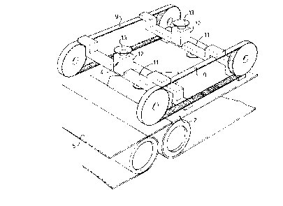
Fig. 1 shows a perspective side view of the apparatus according
to the invention;
Fig. 2 shows a plan view of the apparatus according to the
invention;

- CA 022l99~7 lss7-ll-03
Fig. 3 shows a perspective longitudinal drive in more detail;
and
Fig. 4 shows spacing and rotating of a number of triangular
articles.
In figures 1 and 2 the apparatus of the invention is
schematically shown. It comprises a conveyor 2 for transporting
triangular articles, such as food products 1. Conveyor 2 is present
between a feed conveyor 5 and a discharge conveyor 6. ConveyoL 2 is
operated with a constant speed. Above conveyor 2 a longitudinal drive
comprising a belt loop 3 is provided. Belt loop 3 is driven by motor 7
the space of which is controlled by control 10 according to a
predetermined program. Sensor means 8 are connected to control means 10
and act to start the program.selt loop 3 comprises two parallel belts 9
as is shown in fig. 3 between which cross bars 11 are provided. In the
centre of each cross bar 11 an engagement member 4 is present comprising
a block 12 and a cup 13 wherein cup 13 can rotate relative to block 12.
Discharge belt 6 is provided with a final positioning device
14, comprising a rotatable roller also controlled by control 10 through
its motor 15 and having baffles 16.
In fig. 4 schematically the first most important part of
positioning is elucidated. Starting from a sheet of material two sections
17 and 18 are cut and separated. Each section 17 and 18 is already
provided with further cuts to define substantially triangular articles 1.
Belt 5 moves one of those sections with a relatively low speed. Because
the speed of belt 2 is higher articles 1 of a section are spaced from
each other to provide a room to position them after a 90~ turn behind
each other as is shown in fig. 4. In the trajectory of corlvêyor 5,
article 1 is detected by sensor 8 which triggers movement of belt loop 3
and cup 13 is moved together with the associated parts ihtO engagement
with article 1. Belt loop 3 is moved with about the same speed as belt 5
over a restricted part of their trajectory. Because the speed of belt 2
is higher slippage and pivoting will occur resulting in positioning as is
shown in fig. 2. However, it is also possible to effect an intermittent
movement of belt loop 3. After the article is in the correct position at
the end of belt 2 disengagement between cup 13 and the related article is
effected. Final adjustment is realised by baffle 16 which is stationary
for a short while and during which the articles abut this baffle after
that article 1 is discharged through belt 6.
The device described the above functions as follows:

CA 022l99~7 l997-ll-03
A number of adjacent articles 1 for example from sections 17 or
18 is continuously fed from feed conveyor 5. The front most article 1 is
observed by sensor 8. If its presence is confirmed belt loop 3 which runs
with a relatively low speed or is stationary is activated such that left
engagement member 4 is no longer supported by guide 19 and drops on
article 1. Engagement is effected in the transferred part between belt 5
and 2 but it must be clear that such engagement can also be realized on
belt 5 or on belt 2.
At entering belt 2 the speed of belt loop 3 is increased such
that a spacing is effected between two adjacent articles 1. This spacing
is necessary to effect sufficient room for rotation. It is at the same
time possible to subject the lower side of the article to a higher speed
for instance by having belt 2 rotated with a higher speed than belt 5.
After spacing is effected somewhere in the middle of belt 2 the
speed of the related engagement member 4 is decreased while belt 2
continues to move. Because of that the positioning action according to
the invention is effected.
The subsequent engagement member 4 is in a position near guide
19 and ready to engage a subsequent article 1. As soon as such article 1
is sent the speed of belt loop 3 is increased and so on. After being
positioned article is based on this charge conveyor 6. It must be
understood that conveyor belt can have an increased length.
Although the invention has been described referring to a
preferred embodiment of the invention it will be immediately clear for
the person skilled in the art that many obvious changes can be effected
without leaving the scope of protection as defined in the enclosed
claims.
*****

Representative Drawing
A single figure which represents the drawing illustrating the invention.
Administrative Status

2024-08-01:As part of the Next Generation Patents (NGP) transition, the Canadian Patents Database (CPD) now contains a more detailed Event History, which replicates the Event Log of our new back-office solution.

Please note that "Inactive:" events refers to events no longer in use in our new back-office solution.

For a clearer understanding of the status of the application/patent presented on this page, the site Disclaimer , as well as the definitions for Patent , Event History , Maintenance Fee  and Payment History  should be consulted.

Event History

Description Date
Time Limit for Reversal Expired 2003-11-03
Application Not Reinstated by Deadline 2003-11-03
Deemed Abandoned - Failure to Respond to Maintenance Fee Notice 2002-11-04
Inactive: Abandon-RFE+Late fee unpaid-Correspondence sent 2002-11-04
Letter Sent 2002-03-01
Inactive: Correspondence - Transfer 2002-01-29
Inactive: Office letter 2002-01-02
Application Published (Open to Public Inspection) 1998-05-04
Inactive: Single transfer 1998-03-16
Amendment Received - Voluntary Amendment 1998-03-16
Inactive: Correspondence - Formalities 1998-03-16
Inactive: First IPC assigned 1998-03-05
Classification Modified 1998-02-24
Inactive: IPC assigned 1998-02-24
Inactive: Courtesy letter - Evidence 1998-02-03
Inactive: Filing certificate - No RFE (English) 1998-01-27
Filing Requirements Determined Compliant 1998-01-27
Application Received - Regular National 1998-01-26

Abandonment History

Abandonment Date Reason Reinstatement Date
2002-11-04

Maintenance Fee

The last payment was received on 2001-10-30

Note : If the full payment has not been received on or before the date indicated, a further fee may be required which may be one of the following

  • the reinstatement fee;
  • the late payment fee; or
  • additional fee to reverse deemed expiry.

Please refer to the CIPO Patent Fees web page to see all current fee amounts.

Fee History

Fee Type Anniversary Year Due Date Paid Date
Application fee - standard 1997-11-03
Registration of a document 1998-03-16
MF (application, 2nd anniv.) - standard 02 1999-11-03 1999-10-19
MF (application, 3rd anniv.) - standard 03 2000-11-02 2000-10-30
MF (application, 4th anniv.) - standard 04 2001-11-05 2001-10-30
Registration of a document 2001-11-07
Owners on Record

Note: Records showing the ownership history in alphabetical order.

Current Owners on Record
VAN DER ZON VAN DER WIEL, WILHELMINA JOHANNA CATHARINA MARIA
CSM NEDERLAND B.V.
Past Owners on Record
PETRUS WILHELMUS MARIA (DECEASED) VAN DER ZON
Past Owners that do not appear in the "Owners on Record" listing will appear in other documentation within the application.
Documents

To view selected files, please enter reCAPTCHA code :


To view images, click a link in the Document Description column. To download the documents, select one or more checkboxes in the first column and then click the "Download Selected in PDF format (Zip Archive)" or the "Download Selected as Single PDF" button.

List of published and non-published patent-specific documents on the CPD .

If you have any difficulty accessing content, you can call the Client Service Centre at 1-866-997-1936 or send them an e-mail at CIPO Client Service Centre.


Document
Description 
Date
(yyyy-mm-dd) 
Number of pages   Size of Image (KB) 
Representative drawing 1998-05-20 1 16
Cover Page 1998-05-20 1 47
Drawings 1998-03-16 2 53
Abstract 1997-11-03 1 10
Description 1997-11-03 5 249
Drawings 1997-11-03 2 48
Claims 1997-11-03 2 88
Filing Certificate (English) 1998-01-27 1 165
Courtesy - Certificate of registration (related document(s)) 1998-06-15 1 117
Reminder of maintenance fee due 1999-07-06 1 112
Reminder - Request for Examination 2002-07-04 1 128
Courtesy - Abandonment Letter (Maintenance Fee) 2002-12-02 1 176
Courtesy - Abandonment Letter (Request for Examination) 2003-01-13 1 167
Correspondence 1998-02-02 1 32
Correspondence 1998-03-16 1 58
Correspondence 2002-01-02 1 15
Fees 2001-10-30 1 31
Fees 1999-10-19 1 26
Fees 2000-10-30 1 32