Note: Descriptions are shown in the official language in which they were submitted.
CA 02220096 1997-11-03
DESCRIPTION
MOLDED ARTICLE HAVING A PHOTOCATALYTIC FUNCTION
Technical Field
The present invention relates to a molded article having a
photocatalytic function and effective in deodorization, sterilization and
stain resistance.
Background Art
Metal oxides such as titanium oxide (TiO2) have a function of
decomposing organic compounds which are in contact therewith or
present close thereto by oxidization or reduction when excited by
ultraviolet rays, and thus are called photocatalytic semiconductors.
This function is well known and is utilized in a variety of
applications. For example, Unexamined Japanese Patent Publication No.
62-66861 discloses an arrangement in which a photocatalytic element
having a photocatalytic semiconductor applied to the surface of its base,
which is in the form of a film, bead, board or fibrous element, is placed
in a glass tube and gas or liquid is circulated through the glass tube.
Also, Unexamined Japanese Patent Publication No. 1-143630 discloses
an arrangement in which gas or liquid is circulated through a
photocatalytic element having a photocatalytic semiconductor applied to
the surface of its base which is in the form of a lattice, plate, particle,
pleat or net. Further, Unexamined Japanese Patent Publication No. 4-
61933 discloses an arrangement in which a photocatalytic semiconductor
is applied directly to a stainless steel pipe or a porous fine tube.
In the arrangement of the conventional photocatalytic elements,
CA 02220096 1997-11-03
the photocatalytic semiconductor is applied to a surface of a base which
is a member (tube or plate) having a predetermined shape suitable for its
use. In such cases, it is difficult to make a functional area of the
photocatalytic semiconductor much greater than the surface area of the
base. Further, in order for the photocatalytic semiconductor to be
~ applied to the surface of the base, usually the photocatalytic
semiconductor in a sol state is applied to the surface of the base and then
the base with the photocatalytic semiconductor applied thereto is baked
at a predetermined temperature (50 to 500~C). If, however, the base has
10 a complicated shape, it may be difflcult to make the photocatalytic
semiconductor applied to an inside surface of the base, or the base may
be deformed due to heat. In addition, if the base is complicated in shape,
it is difficult to irradiate its inside surface with ultraviolet rays.
Disclosure of Invention
An object of the present invention is to provide a molded article
with a photocatalytic function capable of having a desired shape and a
contact area much larger than an outside surface area thereof, and being
sufficiently irradiated with ultraviolet rays even at an inner surface
thereof, as needed.
According to one aspect of the present invention, a molded article
is produced by gathering unit particles such as glass beads, bonding them
one another to a desired shape as a whole, and then forming a
photocatalytic functional layer on a surface of each particle.
The unit particles are filled and packed in a mold, and are heated
while being lightly pressed due to their own weight and the like to
CA 02220096 1997-11-03
thereby fusion-bond the unit particles to one another. Alternatively, the
unit particles are bonded to one another by an adhesive. When bonding,
the degree of pressure application and the temperature are set so that the
particles maintains their shapes and intercommunicating gaps are formed
5 among the particles. When using an adhesive, it is necessary to chose a
suitable adhesive (e.g., water glass or low-melting glass frit) which will
not affect properties of the unit particles and the photocatalytic
semiconductor and has an adequate durability in using the molded article
as the photocatalytic element.
The molded article produced by gathering unit particles is
characterized in capability of having a free shape, for example, blocks of
various three-dimensional shapes, such as a tube, gutter, vessel and
corrugated plate. Especially, it makes it possible to select shapes of
components which have been physically or economically impractical to
15 produce by conventional techniques and shapes suitable for use in
various apparatuses. Furthermore, the molded article can have shapes,
for example, of natural thing such as fish, ~nim~l or leaf.
The photocatalytic functional layer is formed, for example, by a
process of dipping the molded article into a sol of optical semiconductor
20 powder, and then drying and baking it. In this case, care should be taken
so that the gaps in the molded article are not clogged with the optical
semiconductor layer and that the molded article is not deformed, or the
particles are not changed in property or decomposed in baking.
According to another aspect of the present invention, a molded
25 article is produced by gathering and ent~n~.ling unit filaments, such as
CA 02220096 1997-11-03
glass-wool or glass fibers, forming the entangled filaments into a required
overall shape by heating, and forming a photocatalytic functional layer on
a surface of each filament.
For the material of the unit filaments, glass (soda-lime glass,
S borosilicate glass, silica glass, etc.) or synthetic resin (acrylic,
polystyrene, polycarbonate, etc.) can be used. The unit filament may be
in the form of a fibrous element, thread, fiber or string. However, the
material used for the unit filaments needs to have at least a certain degree
of transparency with respect to ultraviolet rays, and in the molded state,
10 the unit filaments have a structure that randomly bent filaments have
points of contact with one another and are fixed in place at their points of
contact. The unit filaments are fixed to one another mainly by mutual
friction and also by bonding.
The density of filaments in the molded article varies depending on
15 uses, from a density equivalent to that of felt to a density equivalent to
that of a coarse basket; in any case, gaps are formed among the
filaments.
In the case where an ultraviolet ray can be substantially uniformly
radiated to the entire molded article, metal (stainless steel, aluminum, tin,
20 steel), wood, etc. can also be used.
The photocatalytic functional layer is formed by a process similar
to that described above. In this case, care should be taken so that the
gaps between the filaments will not be clogged with the optical
semiconductor layer and that the molded article is not deformed, or the
25 filaments are not disconnected or decomposed due to heat in baking.
CA 02220096 1997-11-03
Before molding, an aggregate of the unit particles or the unit
filaments may be mixed with particles made of ultraviolet radiating
material of a spontaneous emission type or a light storage type, or with
particles obtained by mixing such an ultraviolet radiating material and
glass or polymeric organic resin.
In the case where an aggregate of the unit particles or filaments is
mixed with particles of a spontaneous emission-type luminous ceramic or
a light storage-type luminous ceramic, or with particles obtained by
mixing fine particles of such a ceramic and glass or polymeric organic
10 resin, even after the radiation of ultraviolet rays onto the molded article
is interrupted, the optical semiconductor of the molded article is
continuously excited by ultraviolet rays radiated from the spontaneous
emission-type luminous ceramic particles or radiated from the light
storage-type luminous ceramic particles by consuming the energy stored
15 therein, whereby the photocatalytic function is retained even thereafter.
Moreover, the particles of a spontaneous emission-type luminous ceramic
or light storage-type luminous ceramic normally emit visible lights of
green, blue or orange, and therefore, the emitted visible light can be
utilized for a decoration or guide light in the dark.
By adjusting the composition of the photocatalytic semiconductor
(e.g., by adding an inorganic pigment or metal) or by controlling the heat
treatment in the process of production, it is possible to shift the
wavelength (absorption band) in ultraviolet region necessary for
obtaining the catalytic function. For example, if a small quantity of CrO3
25 is added to TiO2, the absorption band shifts toward the longer
CA 02220096 1997-11-03
wavelength side. This permits the photocatalytic member to be matched
with the emission spectrum characteristic of the spontaneous emission-
type or light storage-type ultraviolet radiating material, whereby a
photocatalytic semiconductor matching the wavelength of the ultraviolet
radiation to be input thereto can be selected.
The photocatalytic semiconductor may be applied in advance only
to surfaces of the unit particles; alternatively, a molded article may be
produced from the unit particles mixed with the spontaneous emission-
type or light storage-type luminous ceramic particles or from the unit
10 particles containing the mixture of both so that the photocatalytic
semiconductor is present over the entire surface of the molded article. In
the former case, the photocatalytic semiconductor does not adhere to the
surfaces of the spontaneous emission-type or light storage-type luminous
ceramic particles or of the mixture particles, so that a larger quantity of
15 ultraviolet radiation is emitted from these particles. Also, in the case
where the light storage-type luminous ceramic particles are contained,
they can absorb incoming ultraviolet rays with higher efficiency.
In the manufacturing process of the molded article, a
photocatalytic function-assisting additive of metal may be added in order
20 to accelerate and complement the photocatalytic reaction.
Brief Description of Drawings
FIG. 1 is a perspective view showing a part of a wall using molded
articles (blocks) according to the present invention;
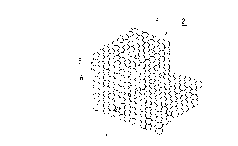
FIG. 2 is a perspective view of a molded article shown in FIG. 1;
FIG. 3a is an enlarged perspective view of part III in FIG. 2; FIG.
CA 02220096 1997-11-03
3b is a schematic diagram showing glass beads and optical
semiconductor particles affixed thereto; FIG. 3c is a diagram showing a
glass bead as a unit particle;
FIG. 4 is an enlarged view of a molded article obtained by molding
5 a mixture of glass beads and particles made of an ultraviolet radiating
material into shape;
FIG. 5 is a perspective view of a fluid purifying device using the
molded articles according to the present invention;
FIG. 6a illustrates an example of the structure of a photocatalytic
10 member according to the present invention, FIG. 6b illustrates an
example of the structure of a conventional photocatalytic member;
FIG. 7 is a schematic diagram of an experimental device;
FIG. 8 is a perspective view showing an example of the molded
article of the present invention formed into a tubular shape;
FIG. 9 is a perspective view showing another example of the
molded article of the present invention formed into a semicylindrical
shape;
FIG. 10 is a perspective view showing still another example of the
molded article of the present invention formed into a ball shape (showing
2() an example of how the molded article is used);
FIG. 11 is an enlarged view of ball-shaped molded articles shown
in FIG. 10;
FIG. 12 is a perspective view of a molded article formed using unit
filaments; and
FIG. 13 is a perspective view of a molded article formed using a
CA 02220096 1997-11-03
mixture of unit filaments and particles made of an ultraviolet radiating
material.
Best Mode of Carrying out the Invention
A filter 1 shown in FIG. 1 is fitted in a partition wall between
adjacent rooms and is used to allow air to flow therethrough to and from
the adjacent rooms.
The filter 1 is constituted by a plurality of light-transmitting, air-
permeable blocks 2, shown in FIG. 2, laid one upon another.
Each whole block 2 is formed as a module so that a desired area
10 can be covered by combining the blocks, and, in this embodiment, a
fitting hole 4 for inserting a fluorescent tube 3 therethrough is formed in a
central part of each block in the lateral direction. The fluorescent tube 3
is an external-excitation type ultraviolet radiating device to emit the light.
The fluorescent tube 3 is an external-excitation type ultraviolet radiating
15 device which emits light by receiving energy from outside.
In this embodiment, as shown in FIG. 3a, the block 2 is obtained
by molding an aggregate of a large number of glass beads 5 (unit
particles) into a desired block shape. Each glass bead 5 (FIG. 3c) is
made of soda-lime glass having transparency to ultraviolet rays and has a
20 diameter of about 5 mm.
The glass beads 5 are filled in an unglazed mold for imparting a
desired shape to a molded article, and are vibrated so that the beads 5
inside the mold are closely packed in the mold. Subsequently, the entire
mold with the beads therein is placed in an electric furnace and is heated
25 at 700~C for 30 minutes with the electric current set at high level while
CA 02220096 1997-11-03
the beads are slightly pressed downward by gravity, followed by natural
cooling taking sufficient time. Owing to the heating, the individual beads
5 are bonded to one another at small spots close to points, so that the
aggregate of the glass beads 5 as a whole is fixed in shape.
The heating temperature and time vary depending on the material
and size of the beads and the shape of the block, and are adjusted to an
extent that the individual beads 5 can be bonded to one another
maintaining their spherical shape (particulate shape). Preferably, the
heating temperature is about 650 to 720~C for the unit particles of glass
beads as in the case of this embodiment, about 450 to 800~C for frit, and
about 120 to 200~C for polycarbonate resin. The molded article
obtained in this way and constituted of an aggregate of the glass beads 5
has interconnecting gaps 6 among the beads 5, and, depending on
location, may have relatively large spaces due to lack of beads 5.
The material of the unit particles is not limited to glass and may be
frit, polycarbonate resin or other material as long as the material used at
least has a certain degree of transparency to ultraviolet rays. Also, the
shape of the unit particles is not limited to sphere as shown in FIG. 3c
and may be polyhedron having surface irregularities, like crushed
particles. The size of the unit particles depends on how the molded
article is used; usually the unit particles used have an average diameter of
about 20,um to 10 mm. In the case where the molded article is designed
to allow passage of gas therethrough as in this embodiment, the size of
the unit particles may be small (20 ,um to 1000 ,um), but where the
molded article is to pass liquid therethrough, the particle diameter must
CA 02220096 1997-11-03
be increased to create larger gaps. Further, in the case where particles
are spread over a slope and liquid is made to flow down the slope, each
particle used may be as large as a ball, rather than a bead. Also, the unit
particles may be hollow particles like glass balloons. As the glass beads,
5 commercially available GB201M (commercial name: a product of
Toshiba-Ballotini Co., Ltd., each bead having a particle diameter of 0.71
to 1.00 mm) can be used.
The molded aggregate of the glass beads 5 is in its entirety dipped
into a sol prepared beforehand using "TO SOL" (a product of Tanaka
1() Transfer Printing Co., Ltd.), shaken well so that the gaps 6 may not be
clogged with the sol, and then dried at 45~C for 10 hours. In this
manner, the surfaces of the individual beads 5 constituting an
intermediate molded article are coated with a photocatalytic
semiconductor 8, and then the intermediate molded article is baked at
400~C for 30 minutes, thereby fixing optical semiconductor particles (in
this case, TiO2) on the surfaces of the glass beads 5 (FIG. 3b) to form a
photocatalytic functional layer (in this case, coating) thereon. The
baking process is necessary for fixing TiO2, but adequate care must be
given to the baking temperature and duration so as not to cause
deformation of the molded article or change in shape of the particles.
For the photocatalytic semiconductor, TiO2, ZnO, SrTiO3, CdS,
CdO, CaP, InP, In2O3, CaAs, BaTiO3, K2NbO3, Fe 2~ ~ Ta 20 ~
WO3SaO2Bi203, NiO, Cu20, SiC, SiO 2) MoS 2 MoS ~ InPb, RuO 2 CeO 2
etc. can be used.
TiO2 in the form of sol is commercially available as "STS-20"
CA 02220096 1997-11-03
(commercial name: a product of Ishihara Sangyo Kaisha, Ltd.), "TO
SOL" and "PTO SOL" (commercial names: products of Tanaka Transfer
Printing Co., Ltd.). The particle diameter of TiO2 in these sols is 0.01 to
0.07 ,um. The wavelength of ultraviolet rays for exciting these particles
5 is varied depending on the kind of particle.
As an additive for providing a complementary function such as
mildew resistance and sterilization, Pt, Ag, RuO2, Nb, Cu, SnNiO, etc.
may be used.
The completed block 2 (molded article having a photocatalytic
10 function) has a translucent white color, a large number of communicating
holes interconnecting the gaps 6, and a total surface area which is three
to four times as large as the surface area of a solid block.
The blocks 2 are laid up one upon another, as shown in FIG. 1, to
form the filter 1 constituting part of the wall. Opening and closing of the
15 door or movement of a person causes the air in the spaces on the
opposite sides of the filter 1 to flow in either direction through a large
number of gaps 6. In this case, if the surfaces of the filter 1 are being
irradiated with ultraviolet rays from fluorescent lamps (external-
excitation type ultraviolet radiating devices) etc. in the room, then the
20 photocatalytic functional layers of the blocks 2 are activated, so that
organic compounds in the air which come into contact with the layers are
decomposed (oxidized or reduced) for deodorization and removal of
harmful floating organic matter, thereby producing sterilizing effect too.
In the case where the blocks 2 are thick or the space on one side of
25 the filter is dark, fluorescent tubes 3 are inserted through the fitting holes
CA 02220096 1997-11-03
4 of the blocks 2 and are lit. By doing so, the wall surfaces of the filter 1
can be made luminous to illuminate the interior of the room, and the
blocks 2 are irradiated with ultraviolet rays from inside, so that the
photocatalytic functional layers are activated to a high level. As a result,
5 the deodorizing function and the sterilizing function are enhanced.
The intermediate molded article, which is a mere aggregate of the
glass beads 5, has a considerable degree of transparency to ultraviolet
rays, but the photocatalytic semiconductor is translucent and absorbs
ultraviolet rays at its surface, so that ultraviolet rays radiated on the
10 surface of the molded article (final product) having the photocatalytic
functional layer formed thereon tends to fail to reach the interior or inside
surface of the molded article. In such a case, it is extremely effective to
provide external-excitation type ultraviolet radiating devices such as
fluorescent tubes may be arranged inside the blocks 2 in enhancing the
15 photocatalytic function of the blocks 2.
The fluorescent tubes 3 may be replaced with other external-
excitation type ultraviolet radiating devices such as mercury lamps,
xenon lamps, black-light lamps or halogen lamps.
The filter 1 may also be used as an outlet filter for a duct which
20 introduces air into an underground passage.
The block 2 shown in FIG. 1 may alternatively be obtained as
follows: After the photocatalytic functional layer is formed beforehand
on the surface of each glass bead 5 (unit particle made of an ultraviolet
ray-transmitting material), the glass beads 5 having the photocatalytic
25 functional layer formed thereon and particles 9 made of a light storage-
CA 02220096 1997-11-03
type ultraviolet radiating material are mixed together to obtain an
aggregate of given shape, as shown in FIG. 4, and the particles 5 and 9
are bonded to one another in a manner such that their particulate shapes
are maintained. For the light storage-type ultraviolet radiating material,
the light-storage-type luminous ceramic "LUMINOVA" (a product of
Nemoto & Company Ltd.) may be used. Alternatively, fine particles
obtained by crushing the light storage-type luminous ceramic may be
mixed with glass or polymeric organic resin and the mixture may be
formed into beads (mixture particles 9~ having a particle diameter
10 equivalent to that of the beads 5. As the photocatalytic semiconductor,
the aforementioned "TO SOL" (a product of Tanaka Transfer Printing
Co., Ltd.) may be used, and the molded article can be obtained by a
molding process similar to that described above.
Although the photocatalytic functional layer is formed beforehand
15 on the surface of each glass bead 5, the surfaces of the glass beads come
into contact with one another and are bonded together during heating,
and thus the light storage-type iuminous ceramic particles 9 or the
mixture particles 9' can be considered to be caught in position by the
surrounding glass beads 5.
A spontaneous emission-type ultraviolet radiating material
(spontaneous emission-type luminous ceramic) is a material that
consumes its internal energy to emit light by itself and utilizes radioactive
decay of radium or promethium, and the emitted light includes an
ultraviolet region. Presently, a lump obtained by solidifying refined
25 powder of rocks cont~inin~ such a material is again crushed and the thus-
CA 02220096 1997-11-03
14
obtained crushed particles are used.
The light storage-type ultraviolet radiating material (light storage-
type luminous ceramic) is a material that obtains energy from outside and
emits light by releasing the energy, and the emitted light includes an
5 ultraviolet region. As such a material, "LUMINOVA" (commercial
name: a product of Nemoto & Company Ltd.) and "KEPRUS"
(commercial name: a product of Next Eye Co., Ltd.) are commercially
available. Each of these products contains strontium aluminate (SrAl204)
as a main component, and other components such as high-purity alumina,
10 strontium carbonate, europium, dysprosium, etc. The peak point in the
absorption spectrum is at 360 nm, and the particle diameter is 20 to 50
,um. The crushed particles, before undergoing fine crushing process may
be directly used.
Some of the commercially available products tend to deteriorate
15 largely by absorbing moisture; therefore, they may be mixed with glass
or a transparent polymeric organic resin such as polycarbonate prior to
actual use.
The block obtained is used in the same manner as in the
aforementioned example. In this case, however, even after the
20 fluorescent tubes 3 are turned off, ultraviolet rays are continuously
radiated from the light storage-type luminous ceramic particles 9 or the
mixture particles 9', which have been irradiated with ultraviolet rays until
then to store the ultraviolet radiate energy, whereby the surrounding
photocatalytic functional layer is activated and the catalytic function is
25 retained. Therefore, even in the nighttime during which no person is
CA 02220096 1997-11-03
present in the room, deodorization and sterilization effects continue,
making it possible to prevent uncomfortable odor from rem~ining in the
room.
A similar molded article can be obtained also by a process in
5 which, first, the glass beads 5 and the light storage-type luminous
ceramic particles 9 or the mixture particles 9' are heated and bonded to
one another to be molded into shape, and the entire molded article is
dipped into a sol of photocatalytic serniconductor, dried, and then baked.
According to this process, however, the irradiation efficiency with which
10 the light storage-type luminous ceramic particles 9 or the mixture
particles 9' are irradiated with ultraviolet rays and the radiant efficiency
with which the particles 9 or 9' radiate ultraviolet rays therefrom are
negatively affected by the photocatalytic functional layer adhering to the
surfaces of the particles 9 or 9'.
FIG. 5 shows a fluid purifying device wherein a plurality of filter
blocks 15 are arranged in a passage constituted of top, bottom, left and
right glass plates 14a to 14d.
Each of the filter blocks 15 is obtained by molding glass beads 5,
each having a photocatalytic functional layer (in this example, TiO2
20 coating) formed on its surface, into the shape of rectangular
parallelepiped. Three fluorescent tubes 3 are arranged along each of the
left and right glass plates 14c and 14d, and with these fluorescent tubes
lit, gas or liquid is made to pass from the front side to the rear side. The
gas or liquid, when coming into contact with the photocatalytic functional
25 layer while passing through the filter blocks 15, undergoes deodorization,
CA 02220096 1997-11-03
16
decomposition of noxious matter, sterilization, etc.
This type of filter tends to have its performance declined after long
use due to accumulation of decomposed matter on the filter blocks, thus
requiring regular washing. In washing, the filter blocks (molded articles)
5 of this example, each obtained by bonding and molding the unit particles
having a filtering function into shape, can individually and easily be
detached one another and washed like a unit. In addition, since the small
beads 5 need not be separated, maintenance of the purifying device can
be done with ease even when it is of a large size.
The capacity of the filter of FIG. 1 or of the fluid purifying device
of FIG. 5 to decompose organic compounds is much higher than
conventional photocatalytic members, since the total surface area of the
photocatalytic functional layer is larger. This will be explained with
reference to the results of experiments performed using photocatalytic
members shown in FIGS. 6a and 6b.
Photocatalytic Member A (glass beads-molded article according to the
present invention)
Glass beads: GB604M (a product of Toshiba-Ballotini Co., Ltd.);
particle diameter: 4.0 mm on average.
Molding: The glass beads were put in a bowl-shaped unglazed
vessel, then heated in an atmosphere of 700~C for 30 minutes, and
cooled. The molded article thus obtained has an overall shape whose
spherical portions are cut flat by a plane. Each flat portion has a
diameter of 130 mm, and its central part has a thickness of 15 mm. The
total surface area of a solid article of the same size is 320 cm2. The glass
CA 02220096 1997-11-03
beads were arranged in the form of pyramid (FIG. 6), the total surface
area is 199 cm3 x 2.22/0.4 = 1104.45 cm2, and the void volume is 199
cm3 x 25.95% = 51.64 cm3.
Photocatalytic semiconductor: STS-21 (a product of Ishihara
S Sangyo Kaisha, Ltd.; neutral sol of TiO2; particle diameter: 0.07 ,um) is
used in the form of a solution containing 20 wt% of the photocatalytic
semiconductor. The glass beads were dipped in this solution for coating,
dried, and then baked at 400~C for 30 minutes. The coating formed on
the surfaces of the beads has a thickness of 2 to 3 ,um.
10 Photocatalytic Member B (conventional article having a base applied
with photocatalytic semiconductor):
Base: Decorative plate "KERAMIT" (commercial name: a product
of Clayburn Ceramics Co., Ltd.; 150 mm x 220 mm x 4 mm (thickness)),
functional surface area: 330 cm2.
Photocatalytic semiconductor: STS-21: Under the same conditions
as the above case, a solution of the photocatalytic semiconductor was
prepared, and the decorative plate was dipped in the solution, dried and
baked. The thickness of the coating was 2 to 3 ,um.
[Experimental Device (FIG. 7)]
Two vessels, a, (330 mm x 330 mm x 40 mm) made of float glass
and 5 mm thick were prepared, the photocatalytic member A was put in
one vessel and the photocatalytic member B in the other. Equal
quantities of colored water b, being colored by a solution containing
0.049% of POLLUX BLUE PM-B (commercial name: a product of
25 Sumika Color Co., Ltd.), were poured into the respective vessels until
CA 02220096 1997-11-03
18
the photocatalytic members A and B were completely submerged, and
the vessels were covered with float glass. The colored water had pH of
5.5 to 6.5. When the colored water was poured into the vessels a, the
liquid temperature was 13~C and the room temperature was 20~C. Two
5 black-light lamps c (40 W) were arranged about 50 cm above the vessels,
and two similar black-light lamps were arranged about 80 cm below the
vessels.
POLLUX BLUE PM-B has the composition of Phthalocyanine
Blue/polyoxyalkylene alkylarylether/organic nitrogen-based antiseptic
10 agent/silicon-based antifoaming agent and is nonionic, and the coloring
component is decomposed not by ultraviolet radiation but solely by
organic decomposition.
[Results of Experiments]
The black-light lamps c were lit, and change in color of the colored
15 water b was observed at intervals of 30 minutes. As a result, in both of
the photocatalytic members A and B, the color apparently became lighter
and lighter with the passage of time to an extent that a dark-blue
sediment was observed in the vessels a. However, it took 12 hours and
30 minutes for the photocatalytic member A and 61 hours and 30 minutes
20 for the photocatalytic member B until almost all coloring component is
deposited to make the colored water nearly transparent. Thus, it was
found that the photocatalytic member A had a decomposition capacity
about five times as high as that of the photocatalytic member B.
FIGS. 8 and 9 show molded articles formed into tubular and cover-
25 shaped blocks 2, respectively, according to the present invention for use
CA 02220096 1997-11-03
19
with lighting apparatus. The photocatalytic functional layers of the
covers are activated by ultraviolet rays emitted from the fluorescent tubes
3 arranged inside the covers, and air flow passing through the gaps 6 of
the covers is produced by the light emitted from the fluorescent tubes 3,
5 thus providing a deodorizing/sterilizing function. Compared with
ordinary covers, the photocatalytic functional layers of these covers have
a much larger surface area, thus providing an enhanced photocatalytic
function. Also, the covers having intricate shape can be formed
relatively easily as needed.
FIGS. 10 and 11 show molded articles formed into ball-shaped
blocks 2 according to the present invention. These blocks are put into a
water tank 10 for keeping fish etc., for example, and are irradiated with
ultraviolet rays from an ultraviolet radiating device 11 arranged outside.
Each of the ball-shaped blocks 2 has a large number of interconnecting
15 gaps 6 to allow air bubbles and water flow produced by a filtering device
12 to pass through the interior of each block 2, thereby decomposing
harmful organic compounds (waster matter) in the water. These blocks
are low in water flow resistance and easy to handle at the time of
washing, compared with an ordinary device consisting of particles of an
20 ion exchange resin are merely filled in a tube. In addition, there is no
particular restriction on the location where the blocks are to be arranged.
FIG. 12 shows a block 2 which is obtained by randomly entangling
glass fibers 13 (unit filaments made of an ultraviolet ray-transmitting
material) having an average diameter of 100 ,um in cross section and by
25 forming the entangled fibers into a cylindrical shape in a manner such
CA 02220096 1997-11-03
that gaps are present among the fibers 13. When the fibers 13 are
molded into shape with heat applied thereto, the fibers at the surface are
fixed into shape due to heat while the inner entangled fibers are
frictionally fixed in place at their points of contact with one another.
5 Therefore, the overall shape of the molded article is never deformed.
The intermediate molded article obtained in this manner is dipped into
the "TO SOL" (a product of Tanaka Transfer Printing Co., Ltd.), then
dried, and again put in a mold for baking so as to prevent deformation of
the shape. Thus, the molded article having a photocatalytic functional
10 layer formed on the surface of each filament is finally obtained. This
block can be molded into a relatively free form, as in the aforementioned
example using the beads 5. Also, by using glass fibers with different
diameters, it is possible to obtain a variety of blocks suited for diverse
uses.
As the material of the unit filaments, glass (soda-lime glass,
borosilicate glass, silica glass, etc.) or synthetic resin (acrylic resin,
polystyrene, polycarbonate, etc.) may be used.
The block 2 has a hole 4 formed in its central part in the lateral
direction, and this hole 4 can be used as a fitting hole for inserting
20 therethrough a fluorescent tube serving as an external-excitation type
ultraviolet radiating device which emits light by receiving energy from
outside.
FIG. 13 shows a molded article similar to that shown in FIG. 12,
but the former includes the light storage-type luminous ceramic particles
25 9 or the aforementioned mixture particles 9'. This molded article may be
CA 02220096 1997-11-03
21
obtained by first mixing the glass fibers 13 with the light storage-type
luminous ceramic particles 9 or the mixture particles 9', then molding the
fibers with the particles into shape with heat applied thereto, and dipping
the entire molded block into a sol of an optical semiconductor.
S Alternatively, the light storage-type luminous ceramic particles 9 or the
mixture particles 9' may be allowed to be caught in the molded article
shown in FIG. 12, and then the molded article with the particles may be
baked again moderately so that the particles can be fixed and will not be
separated from the block.
Like the example shown in FIG. 13, the block 2 has a hole 4
formed in its central part in the lateral direction, and this hole 4 can be
used as a fitting hole for inserting therethrough a fluorescent tube serving
as an external-excitation type ultraviolet radiating device which emits
light by receiving energy from outside.
In the manufacturing process of the aforementioned molded
articles, metal (Pt, Ag, Rh, RuO2, Nb, Cu, Sn, NiO, etc.) may be added
as a photocatalytic function-assisting additive for accelerating and
complementing the photocatalytic reaction.
The molded article according to the present invention is constituted
20 of an aggregate of unit particles or unit filaments, and accordingly, a
molded article having a photocatalytic function can be shaped into a
relatively free form. Thus, surface area of the molded article, that is, the
area of the photocatalytic functional layer, can be made much greater that
of conventional one, thus providing an enhanced photocatalytic effect.
25 Where an external-excitation type ultraviolet radiating device is arranged
CA 02220096 1997-11-03
inside the molded article, the large surface area of the photocatalytic
functional layer not only can be utilized more effectively but also a
higher photocatalytic function not only can be obtained.