Language selection

Search

Patent 2220128 Summary

Third-party information liability

Some of the information on this Web page has been provided by external sources. The Government of Canada is not responsible for the accuracy, reliability or currency of the information supplied by external sources. Users wishing to rely upon this information should consult directly with the source of the information. Content provided by external sources is not subject to official languages, privacy and accessibility requirements.

Claims and Abstract availability

Any discrepancies in the text and image of the Claims and Abstract are due to differing posting times. Text of the Claims and Abstract are posted:

  • At the time the application is open to public inspection;
  • At the time of issue of the patent (grant).
(12) Patent Application: (11) CA 2220128
(54) English Title: ADJUSTABLE STEERING COLUMN
(54) French Title: COLONNE DE DIRECTION REGLABLE
Status: Deemed Abandoned and Beyond the Period of Reinstatement - Pending Response to Notice of Disregarded Communication
Bibliographic Data
(51) International Patent Classification (IPC):
  • B63H 25/52 (2006.01)
  • B63H 21/22 (2006.01)
  • B63H 25/02 (2006.01)
(72) Inventors :
  • KALHOK, DAVID (Canada)
  • LAPOINTE, LUC (Canada)
(73) Owners :
  • BOMBARDIER INC.
(71) Applicants :
  • BOMBARDIER INC. (Canada)
(74) Agent: SMART & BIGGAR LP
(74) Associate agent:
(45) Issued:
(22) Filed Date: 1997-11-04
(41) Open to Public Inspection: 1999-05-04
Availability of licence: N/A
Dedicated to the Public: N/A
(25) Language of filing: English

Patent Cooperation Treaty (PCT): No

(30) Application Priority Data: None

Abstracts

English Abstract


An adjustable steering column for use with a personal watercraft or similar
vehicles.
The adjustable steering column comprises a steering column base fixed to the
watercraft, an
upper steering column connected to the steering column base, the upper
steering column
being moveable between a first position and second position, and an adjustment
mechanism
for moving the upper steering column between the first and second positions.
Preferably, the
adjustment mechanism includes a screw with a knob on one end and a ball joint
on the other
end. The adjustment screw is manually operable to pivot the upper steering
column with
respect to the steering column base. An adjustable steering column allows
riders of different
size to vary the height and angle of the steering column to optimize comfort
and control.


Claims

Note: Claims are shown in the official language in which they were submitted.

The embodiments of the invention for which an exclusive privilege is claimed
are as
follows:
1. A personal watercraft, including an adjustable steering column whereby, in
operation, the
adjustable steering column can be raised or lowered to accommodate riders of
varying
height.
2. An adjustable steering column for use with a personal watercraft, said
adjustable steering
column, in operation, being capable of being raised or lowered by an
adjustment screw.
3. An adjustable steering column as claimed in Claim 2 comprising an upper
steering
column, a pair of handlebars and a steering column base, said upper steering
column and
said steering column base being pivotally connected by a revolute joint.
4. An adjustable steering column as claimed in Claim 2 further comprising a
ball end on one
end of said adjustment screw, said ball end being adapted to move upwardly and
downwardly in a ball housing and said adjustment screw being adapted to rotate
within
a threaded housing, said ball housing being fixed within said upper steering
column.
5

Description

Note: Descriptions are shown in the official language in which they were submitted.


CA 02220128 1999-02-04
Adjustable Steering Column
Field of the Invention
The present invention pertains to personal watercraft, and more particularly
to an
apparatus for adjusting the height and inclination of a steering column
mounted on a personal
watercraft.
Background of the Invention
Since the introduction ten years ago of the first sit-down personal watercraft
(PWC), the
design of these products has evolved rapidly to meet the varied needs of
riders, both recreational
and competitive. The factors that typically determine the design of personal
watercraft are
power, acceleration, stability, fuel efficiency, safety, appearance and
ergonomics. From an
ergonomic standpoint, the height of the handlebars is an important factor in
the overall level of
comfort for riders of personal watercraft. Handlebars that are either too low
or too high may
make it difficult to effectively steer the personal watercraft and,
furthermore, may tire the rider's
arms if he or she has to hold them in an uncomfortable position. Not only is
the positioning of
the steering column important, but the positioning should preferably be
accomplished quickly
and easily. Since personal watercraft are often rented out at resorts or
shared among friends and
family, it is particularly advantageous if the positioning of the steering
column can be
accomplished quickly and easily, without the need for tools, to accommodate
riders of varying
height. Heretofore, however, manufacturers of personal watercraft have not
concentrated much
on making steering columns adjustable. Thus, there is a need to design a
personal watercraft
whose steering column can be quickly and easily adjusted to a height
appropriate for each rider.
Object and Statement of the Invention
It is thus the object of the present invention to provide a personal
watercraft steering
column that is adjustable so that riders can quickly and easily adjust the
steering column, and
hence the handlebars, to a height and inclination that optimizes their
comfort.
1

CA 02220128 1999-02-04
Other obj ects and features of the invention will become apparent by reference
to the
following description and drawings.
Brief Description of the Drawings
A detailed description of the preferred embodiments of the present invention
is provided
hereinbelow with reference to the following drawings, in which:
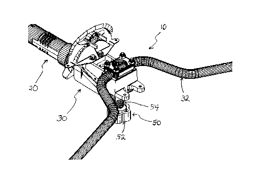
Figure 1 is a perspective view of an adjustable steering column in accordance
with the
invention.
Figure 2 is a side elevational view of the adjustable steering column shown in
Figure l,
wherein the adjustable steering column is in its nominal (intermediate)
position.
Figure 3 is a side elevational view of the adjustable steering column shown in
Figure 1,
wherein the adjustable steering column is in its highest position.
Figure 4 is a side elevational view of the adjustable steering column shown in
Figure 1,
wherein the adjustable steering column is in its lowest position.
In the drawings, the preferred embodiments of the invention are illustrated by
way of
example. It is to be expressly understood that the description and drawings
are only for purposes
of illustration and to facilitate understanding, and are not intended to be a
definition of the limits
of the invention.
Detailed Description of Preferred Embodiments
Referring to Figure 1, an adjustable steering column 10 of the present
invention
comprises a steering column base 20 and an upper steering column 30. A
handlebar 32 is
mounted on the upper steering column 30 for steering a personal watercraft.
2

CA 02220128 1999-02-04
Refernng to Figures 2-4, the upper steering column 30 pivots with respect to
the steering
column base 20 about a revolute joint 24. To adjust the height and inclination
of the upper
steering column 30 with respect to the steering column base 20, the rider
simply turns an
adjustment screw 50.
The adjustment screw 50 comprises an adjustment knob 52 located at one end of
a
threaded shaft 54. The threaded shaft 54 screws through a threaded housing 56
having a
matching pitch. The threaded housing 56 is connected rigidly to the steering
column base 20.
At the other end of the adjustment screw 50, the threaded shaft 54 is
connected to a ball end 58
which forms a spherical joint with a ball housing 60. The ball housing 60 is
connected rigidly
to the upper steering column 30.
To raise the upper steering column 30 and the handlebar 32 with respect to the
steering
column base 20, the rider turns the adjustment knob 52 clockwise (from the
perspective of the
rider) thereby causing the threaded shaft 54 (assuming right-handed threads)
to advance through
the threaded housing 56. When the threaded shaft 54 advances through the
threaded housing 56,
the ball end 58 exerts an upward force on the ball housing 60. This upward
force is transferred
to the upper steering column 30 and thus causes the upper steering column 30
to pivot upward
about the revolute joint 24.
Conversely, to lower the upper steering column 30 and the handlebar 32 with
respect to
the steering column base 20, the rider turns the adjustment knob 52
counterclockwise (again from
the perspective of the rider) thereby causing the threaded shaft 54 (again
assuming right-handed
threads) to retreat through the threaded housing 56. When the threaded shaft
54 retreats through
the threaded housing 56, the ball end 58 exerts a downward force on the ball
housing 60. This
downward force is transferred to the upper steering column 30 and thus causes
the upper steering
column to pivot downward about the revolute joint 24.
To construct the components of the foregoing description, standard engineering
materials,
which are well-known to those skilled in the art, would suffice. Specifically,
in the preferred
3

CA 02220128 1999-02-04
embodiment, the adjustment screw 50 would be constructed of nylon. The ball
housing 60 and
the threaded housing 56 would also be made of nylon or of an equivalent
material which would
minimize wear of the threaded shaft 54 and of the ball end 58. The revolute
joint 24 would be
any standard bearing or bushing, the selection of which is well established in
the art. Finally, the
methods and materials required to design and construct the remaining
components of the
adjustable steering column 10 are well known to those skilled in the art.
The above description of preferred embodiments should not be interpreted in a
limiting
manner since other variations, modifications and refinements are possible
within the spirit and
scope of the present invention. The scope of the invention is defined in the
appended claims and
their equivalents.
4

Representative Drawing
A single figure which represents the drawing illustrating the invention.
Administrative Status

2024-08-01:As part of the Next Generation Patents (NGP) transition, the Canadian Patents Database (CPD) now contains a more detailed Event History, which replicates the Event Log of our new back-office solution.

Please note that "Inactive:" events refers to events no longer in use in our new back-office solution.

For a clearer understanding of the status of the application/patent presented on this page, the site Disclaimer , as well as the definitions for Patent , Event History , Maintenance Fee  and Payment History  should be consulted.

Event History

Description Date
Inactive: IPC expired 2020-01-01
Inactive: IPC from MCD 2006-03-12
Time Limit for Reversal Expired 2003-11-04
Application Not Reinstated by Deadline 2003-11-04
Deemed Abandoned - Failure to Respond to Maintenance Fee Notice 2002-11-04
Inactive: Abandon-RFE+Late fee unpaid-Correspondence sent 2002-11-04
Letter Sent 2000-11-28
Inactive: Cover page published 1999-05-20
Application Published (Open to Public Inspection) 1999-05-04
Inactive: Filing certificate - No RFE (English) 1999-03-25
Inactive: Inventor deleted 1999-03-25
Inactive: Delete abandonment 1999-03-24
Inactive: Abandoned - No reply to Office letter 1999-02-05
Inactive: Correspondence - Formalities 1999-02-04
Inactive: Correspondence - Formalities 1998-11-26
Inactive: Office letter 1998-11-06
Inactive: Single transfer 1998-08-12
Inactive: First IPC assigned 1998-02-24
Classification Modified 1998-02-24
Inactive: IPC assigned 1998-02-24
Inactive: Filing certificate - No RFE (English) 1998-01-29
Filing Requirements Determined Compliant 1998-01-29
Application Received - Regular National 1998-01-28

Abandonment History

Abandonment Date Reason Reinstatement Date
2002-11-04

Maintenance Fee

The last payment was received on 2001-10-19

Note : If the full payment has not been received on or before the date indicated, a further fee may be required which may be one of the following

  • the reinstatement fee;
  • the late payment fee; or
  • additional fee to reverse deemed expiry.

Patent fees are adjusted on the 1st of January every year. The amounts above are the current amounts if received by December 31 of the current year.
Please refer to the CIPO Patent Fees web page to see all current fee amounts.

Fee History

Fee Type Anniversary Year Due Date Paid Date
Application fee - standard 1997-11-04
Registration of a document 1998-08-12
MF (application, 2nd anniv.) - standard 02 1999-11-04 1999-10-20
MF (application, 3rd anniv.) - standard 03 2000-11-06 2000-10-20
MF (application, 4th anniv.) - standard 04 2001-11-05 2001-10-19
Owners on Record

Note: Records showing the ownership history in alphabetical order.

Current Owners on Record
BOMBARDIER INC.
Past Owners on Record
DAVID KALHOK
LUC LAPOINTE
Past Owners that do not appear in the "Owners on Record" listing will appear in other documentation within the application.
Documents

To view selected files, please enter reCAPTCHA code :


To view images, click a link in the Document Description column. To download the documents, select one or more checkboxes in the first column and then click the "Download Selected in PDF format (Zip Archive)" or the "Download Selected as Single PDF" button.

List of published and non-published patent-specific documents on the CPD .

If you have any difficulty accessing content, you can call the Client Service Centre at 1-866-997-1936 or send them an e-mail at CIPO Client Service Centre.


Document
Description 
Date
(yyyy-mm-dd) 
Number of pages   Size of Image (KB) 
Representative drawing 1999-05-19 1 20
Description 1997-11-03 4 174
Drawings 1997-11-03 4 139
Drawings 1999-02-03 4 108
Description 1999-02-03 4 158
Claims 1999-02-03 1 27
Abstract 1999-02-03 1 21
Filing Certificate (English) 1998-01-28 1 165
Request for evidence or missing transfer 1998-11-04 1 110
Filing Certificate (English) 1999-03-24 1 165
Reminder of maintenance fee due 1999-07-05 1 112
Courtesy - Certificate of registration (related document(s)) 2000-11-27 1 113
Reminder - Request for Examination 2002-07-07 1 128
Courtesy - Abandonment Letter (Maintenance Fee) 2002-12-01 1 176
Courtesy - Abandonment Letter (Request for Examination) 2003-01-12 1 167
Correspondence 1998-02-02 1 38
Correspondence 1998-11-05 1 7
Correspondence 1998-11-25 2 79
Correspondence 1999-02-03 12 365
Fees 2000-10-19 1 44