Note: Descriptions are shown in the official language in which they were submitted.
CA 02220325 1997-11-OS
RECOVERY BOILER
BACKGROUND OF THE INVENTION:
Field of the Invention:
The present invention relates to a recovery boiler
for recovering soda component etc. from pulp sent liquor
etc.
Description of the Prior Art:
In a pulp sent liquor generated in paper making
process, there are contained in a large quantity a portion
of organic matters of wood materials and a soda component
added in the process of cooking. So, the spent liquor
(hereinafter referred to as "black liquor") is once
condensed and then burnt in a recovery boiler comprising
a furnace of which main object is to recover the soda
component so that the soda component in the black liquor is
recovered as a sodium carbonate and a sodium sulfide in a
molten state.
Fig. 8 is a schematic view showing a recovery
boiler in the prior art. A black liquor 42a is ejected
from a plurality of black liquor burners 42 into a recovery
boiler 41. On the other hand, a combustion air 40 is fed
thereinto from a primary air nozzle 45a, a secondary air
nozzle 45b and a tertiary air nozzle 45c via a fan 43 and
air dampers 44a, 44b and 44c. And the black liquor 42a is
- 1 -
CA 02220325 1997-11-OS
burnt on a char bed 46 formed at a lower portion of the
boiler.
Generally in the recovery boiler 41, the black
liquor 42a containing comparatively coarse particle sizes is
ejected from the black liquor burners 42 disposed in a mid
portion of the furnace, as shown by arrows of dotted lines
in Fig. 8, to fall down therein while it is being dried by a
furnace combustion gas and then is accumulated on a furnace
floor so as to form the char bed 46 and to be burnt.
With enhancement of an evaporator performance to
condense water content from spent liquor, it is a recent
tendency that a slid concentration in the black liquor 42a,
which had so far been 60%, has been increased to 80% with
result that a boiler combustion efficiency has been
increased, and also concentration of the black liquor itself
is enhanced.
Also, a sufficient quantity of the primary air,
the secondary air and the tertiary air being fed in the
surroundings of the char bed 46, degree of combustion of the
black liquor 42a on the char bed 46 is enhanced, which
results in a combustion state to cause a sharp rise of
nitrogen oxides (hereinafter referred to as "NOx") as object
of pollution control regulations, thus in order to operate
the recovery boiler in accordance with pollution control
regulations, it is indispensable to reduce a quantity of NOx
- 2 -
CA 02220325 1997-11-OS
discharged from a furnace outlet.
One method for reducing the NOX, as considered, is
to generate a combustion zone of reduction atmospheric field
in which air ratio in the surroundings of the char bed is
0.8 or less and to feed an additional air from an upper
portion of the furnace. In this case, however, quantity
all of or any of the primary air, the secondary air and
the tertiary air being reduced necessarily, flow velocity
of air fed into the furnace is lowered and air quantity
distribution in the furnace becomes irregular so that there
occur a non-uniform combustion, a carry-over of unburnt
char, a deformation of the char bed, etc., which makes
holding of a stable combustion difficult.
SUMMARY OF THE INVENTION:
In view of the problems in the prior art, it is an
object of the present invention to provide a recovery boiler
which is able to effect a NOX reduction securely.
In order to attain said object, the present
invention provides a recovery boiler comprising a burner for
ejecting a black liquor into a furnace and a combustion air
nozzle, wherein said combustion air nozzle consists of a
main air nozzle for feeding air so as to form a reduction
atmospheric field where an air ratio in the surroundings of
a char bed formed on a furnace bottom is 0.8 or less, a
- 3 -
CA 02220325 1997-11-OS
first additional air nozzle disposed downstream of said main
air nozzle for feeding air so as to form a reduction
atmospheric field where an air ratio is 1.0 or less and
unburnt components exist and a second additional air nozzle
disposed downstream of said first additional air nozzle for
feeding a shortage of air so as to form a combustion zone
where a combustion completes, and said recovery boiler
further comprises a means for feeding a recirculated gas
or an inert gas together with a combustion air and/or along
a furnace side wall around said char bed. Thereby, there
are formed sequentially a combustion zone of the reduction
atmospheric field of air ratio of 0.8 or less formed by
the main air nozzle, a combustion zone of the reduction
atmospheric field of air ratio of 1.0 or less formed by
the first additional air nozzle and a combustion zone for
completing the combustion formed by the second additional
air nozzle, and a combustion with a reduced quantity of NOx
generation is attained.
Moreover, a recirculated gas or an inert gas is
fed along the furnace side wall around the char bed so as
to form a pneumatic curtain, thereby the furnace side wall
including side wall pipings is prevented from being corroded
by sulfide generated from sulfur component in the black
liquor at the combustion zone of the reduction atmospheric
field.
- 4 -
CA 02220325 1997-11-OS
Also, the present invention provides a recovery
boiler comprising a burner for ejecting a black liquor into
a furnace and a combustion air nozzle, wherein said
combustion air nozzle consists of a main air nozzle for
feeding air so as to form an air ratio in the surroundings
of a char bed formed on a furnace bottom of 0.8 or less and
an additional air nozzle disposed downstream of said main
air nozzle for feeding a shortage of air and said main air
nozzle consists of a primary air nozzle for feeding air
toward between the char bed and the furnace bottom, a
secondary air nozzle for feeding air toward an inclined side
face of the char bed and a tertiary air nozzle for feeding
air downwardly toward a furnace side from an upper portion
of the char bed and directedly toward a direction to
generate a swirling force from a furnace side wall or a
furnace corner. Thereby, the char bed is prevented from
coming nearer to the furnace side wall by the primary air
nozzle so that the char bed configuration becomes
stabilized, and the air distribution in the furnace is
homogenized by the secondary air nozzle and the unburnt char
which is liable to be carried over is suppressed not to be
carried over to the furnace upper portion, thus a stable
combustion is attained.
Also, the present invention provides a recovery
boiler as mentioned immediately above, wherein said primary
- 5 -
CA 02220325 1997-11-OS
air nozzle feeds air at an air flow velocity of 30 m/s or
more and said secondary air nozzle at an air flow velocity
of 50 m/s or more, each with an air quantity of 400 or less
of an entire combustion air, and said tertiary air nozzle
feeds a shortage of air. Thereby, said stabilization of
the char bed configuration, said homogenization of the air
distribution in the furnace and said carry-over of the
unburnt char are attained further accurately and securely
and a stable combustion is accelerated further.
Also, the present invention provides a recovery
boiler comprising a burner for ejecting a black liquor into
a furnace and a combustion air nozzle, wherein said
combustion air nozzle consists of a main air nozzle for
feeding air so as to form a reduction atmospheric field
where an air ratio in the surroundings of a char bed formed
on a furnace bottom is 0.8 or less, a first additional air
nozzle disposed downstream of said main air nozzle for
feeding air so as to form a reduction atmospheric field
where an air ratio is 1.0 or less and unburnt components
exist and a second additional air nozzle disposed downstream
of said first additional air nozzle for feeding a shortage
of air so as to form a combustion zone where a combustion
completes. Thereby, the combustion air supplied from the
main air nozzle forms the reduction atmospheric field of air
ratio of 0.8 or less and even if the additional combustion
- 6 -
CA 02220325 1997-11-OS
air is added downstream thereof from the first additional
air nozzle, the reduction atmospheric field is maintained
with its air ratio of 1.0 or less and then the shortage of
the combustion air is supplied further downstream thereof
from the second additional air nozzle so that the combustion
of the unburnt components completes, thus a low NOx
combustion is attained.
Also, the present invention provides a recovery
boiler comprising a burner for ejecting a black liquor into
a furnace and a combustion air nozzle, wherein said
combustion air nozzle consists of a main air nozzle and a
first additional air nozzle for feeding air so as to form
a reduction atmospheric field where an air ratio in the
surroundings of a char bed formed on a furnace bottom is 1.0
or less and a second additional air nozzle disposed in
plural steps and/or in plural pieces downstream of said
first additional air nozzle for feeding a shortage of air so
as to form a combustion zone where a combustion completes,
and unburnt components generated at said reduction
atmospheric field of air ratio of 1.0 or less formed by a
combustion air from said main air nozzle and said first
additional air nozzle are burnt completely by the air from
said second additional air nozzle. Thereby, as one example,
a combustion air is fed from the main air nozzle consisting
of a primary and a secondary air nozzles and from the first
CA 02220325 2002-02-28
additional air nozzle consisting of a tertiary air nozzle so
as to effect a reduction combustion in the reduction
atmospheric field where the air ratio in th.e surroundings of
the char bed is 1.0 or less, for example 0.8 or less, and an
additional combustion air is fed further downstream thereof
from the second additional air nozzle, consisting of a
quaternary air nozzle for example, disposed in plural steps
and/or plural pieces so that the unburnt components
generated in the reduction atmospheric field in the
1~ surroundings of the char bed are burnt completely. Thus,
such a reduction atmospheric field and a combustion
completion field are formed with an aim that the NOX
generated by the reduction combustion reaction is converted
into N2 and the unburnt components generated are burnt
1!~ completely finally and a stable combustion with reduced NOX
quantity and without unburnt components can be attained.
Also, the present invention provides a recovery
boiler comprising a furnace having a furnace bottom and a
furnace side wall; a burner for ejecting a black liquor into
20 said furnace so as to form a char bed on said furnace
bottom; a combustion air supply system comprising a main air
supply means for feeding air into said furnace so as to form
a reduction atmospheric field with an air ratio of 0.8 or
less surrounding the char bed formed on said furnace bottom,
2~> a first additional air supply means, disposed downstream of
said main air supply means, for feeding air into said
furnace so as to form a reduction atmospheric field where an
_ g
CA 02220325 2002-02-28
air ratio of 1.0 or less and unburnt components exist, and a
second additional air supply means, disposed downstream of
said first additional air supply means, for feeding air so
as to form a combustion zone where combustion completes; and
a means for feeding one of a recirculated and an inert gas
together with combustion air along said furnace side wall.
Also, the present invention provides a recovery
boiler comprising a furnace having a furnace bottom and a
furnace side wall; a burner for ejecting a black liquor into
said furnace so as to form a char bed on said furnace
bottom; and a combustion air supply system comprising a main
air supply means for feeding air into said furnace so as to
form a reduction atmospheric field with an air ratio of 0.8
or less surrounding the char bed formed on .said furnace
bottom, a first additional air supply means, disposed
downstream of said main air supply means, for feeding air
into said furnace so as to form a reduction atmospheric
field where an air ratio of 1.0 or less and unburnt
components exist, and a second additional air supply means,
disposed downstream of said first additional air supply
means, for feeding air so as to form a combustion zone where
combustion completes.
BRIEF DESCRIPTION OF THE DRAWINGS:
In the accompanying drawings:
Fig. 1 is a schematic view of a recovery boiler of
a first embodiment according to the present invention.
- 8a -
CA 02220325 2002-02-28
Fig. 2 is a schematic view of a recovery boiler of
a second embodiment according to the present invention.
Fig. 3 is a cross sectional view taken on line
III-III of Fig. 2.
- 8b -
CA 02220325 1997-11-OS
Fig. 4 is an explanatory graph showing relation
between secondary air flow velocity and 02 distribution-
imbalance of the recovery boiler of Fig. 2.
Fig. 5 is a schematic view of a recovery boiler
of a third embodiment according to the present invention.
Fig. 6 is an explanatory graph showing changes
of S 2 component corresponding to residence time from char
bed upper side to quarternary air nozzle position of the
recovery boiler of Fig. 5.
Fig. 7 is an explanatory graph showing changes
of NOx value corresponding to residence time from char bed
upper side to quarternary air nozzle position of the
recovery boiler of Fig. 5.
Fig. 8 is a schematic view of a prior art recovery
boiler.
DESCRIPTION OF THE PREFERRED EMBODIMENTS:
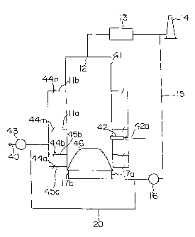
With reference to Fig. 1, a first embodiment
according to the present invention is described. To be
noted is that same parts as those in the prior art are
given same numerals and repeated description is omitted.
In Fig. l, numeral 43 designates a fan for
regulating all the air supply for combustion and a
combustion air from said fan 43 is fed into furnace from a
primary air nozzle 45a and a secondary air nozzle 45b via
- 9 -
CA 02220325 1997-11-OS
air dampers 44a and 44b disposed directedly from upstream to
downstream with its air ratio in the surroundings of a char
bed being adjusted to 0.8 or less. Said primary air nozzle
45a and secondary air nozzle 45b constitute a main air
nozzle.
Likewise, via an air damper 44m, air is fed from
a first additional air nozzle lla with its air ratio being
adjusted to 1.0 or less and further via an air damper 44n,
a shortage of air is fed from a second additional air nozzle
11b. It is to be noted that an optimum position of the
first and the second additional air nozzles 11a, 11b,
respectively, is decided depending on a residence time of
a furnace combustion gas and a number of the position is not
limited to two stages but may be other plural stages.
Also, while optimum air blowing velocity and
direction of the first and the second additional air nozzles
11a, 11b, respectively, are selected depending on a state of
combustion or a state of combustion exhaust gas flow, it
will do basically if such arrangement that the air supplied
may reach a furnace center and may be diffused and mixed
uniformly in the furnace is employed.
By so feeding the combustion air as described
above, there can be formed a combustion zone of reduction
atmospheric field in which air ratio in the surroundings
of the char bed 46 is 0.8 or less, a combustion zone at
- 10 -
CA 02220325 1997-11-OS
an upper portion thereof of reduction atmospheric field in
which air ratio is 1.0 or less and unburnt components exist
and a combustion zone at a further upper portion thereof, in
which the combustion completes, thus NOx generation can be
reduced enough.
In each said combustion zone, reaction is taken
place as follows: that is, in the combustion zone of
reduction atmospheric field in which air ratio is 0.8 or
less, there exists a surplus fuel beyond a chemical
equivalent of oxygen and a portion of the fuel forms a
reduction atmospheric field which burns in a high
temperature combustion atmosphere, thus fuel and nitrogen
(N) component in a black liquor and nitrogen component in
the air present reactions of;
(Chemical equations 1)
CnHn + C02 ~ Cp2 + H20
N + 02 -~ NO,
and then in the combustion zone of reduction atmospheric
field in which unburnt components exist, following reactions
are done:
(Chemical equations 2)
CnHn + 02 ~ H2 + CO + Cn'Hm'
Cn'Hm' + NO ; NHi + N2 + Cn"Hm",
where the symbols of a single comma "," or double commas """
designate activated hydrocarbon radicals.
- 11 -
CA 02220325 1997-11-OS
Further, in the combustion zone of combustion
completion field, following reactions are done:
(Chemical equations 3)
Cn~~Hm~~ + 02 ~ C02 + H20
Cn'Hm' + 02 -~ C02 + H20
CO + H2 + 02 ~ C02 + H20
NHi + 02 ~ NO + N20
or NHi + 02 -~ N2 + H20,
and thus NOx reduction can be attained.
It is to be noted that a combustion gas 12 to be
discharged from a recovery boiler 41 is partially extracted
by a fan 16 via an extraction duct 15 from a passage of the
combustion gas between a heat exchanger 13 and a stack 14
for gas discharge into the air and is ejected from nozzles
17a and 17b into a furnace lower portion along a furnace
side wall including side wall pipings around the char bed.
Thus, a pneumatic curtain is formed along the furnace side
wall by the exhaust gas so extracted and fed into the
furnace again so that a direct contact of sulfide and the
furnace side wall is avoided, thereby corrosion of the
furnace side wall can be prevented.
Also, to be noted is that the nozzles 17a, 17b
are provided in a plural number of pieces and while optimum
ejection direction and velocity of the extracted gas are
naturally decided corresponding to a recovery boiler
- 12 -
CA 02220325 1997-11-OS
configuration, a char bed configuration or a combustion
state, it will do basically if such arrangement that the
extracted gas may go up along the furnace side wall and a
direct contact of sulfide etc. and the furnace side wall may
be avoided is employed. Also, said avoidance of corrosion
of the furnace side wall is applicable within the recovery
boiler, not limited to the reduction atmospheric field
therein.
Further, there can be added also an arrangement
that an inert gas such as a recirculated gas etc. is fed
into the combustion air via the fan 16 and a duct 20.
Next, description is made on a second embodiment
according to the present invention with reference to Figs. 2
to 4. To be noted is that same parts as those described for
the prior art and the first embodiment are given same
numerals in the figures and repeated description is omitted.
Combustion air from a fan 43 is fed from a
primary, a secondary and a tertiary air nozzles 45a, 45b
and 45c, respectively, and from an additional air nozzle lla
via an air damper 44m and a furnace upper portion. Total
quantity of the air fed into the surroundings of a char bed
46 from the primary, the secondary and the tertiary air
nozzles 45a, 45b and 45c is regulated to form an air ratio
of 0.8 or less.
On the other hand, air fed from the primary air
- 13 -
CA 02220325 1997-11-OS
nozzle 45a is 40% or less of an entire combustion air
quantity and the primary air nozzle 45a is of such a
configuration and arrangement that an air flow velocity
becomes 30 m/s or more, thereby the char bed 46 is prevented
from coming nearer to a furnace side wall and thus a char
bed configuration is stabilized always.
Air fed from the secondary air nozzle 45b is 400
or less of the entire combustion air quantity and the
secondary air nozzle 45b is of such a configuration and
arrangement that the air flow velocity becomes 50 m/s or
more, thereby the air reaches a furnace central portion and
an air distribution is homogenized. Relationship between
air flow velocity from the secondary air nozzle 45b and 02
distribution imbalance is shown in Fig. 4.
Air fed from the tertiary air nozzle 45c is a
portion, or 20% or less, of the entire combustion air
quantity and is charged downwardly toward a direction of
the char bed 46, as shown in Fig. 2, and inclinedly from
vicinity of a furnace corner, as shown in Fig. 3, thereby a
swirling force is generated and a carry-over of unburnt char
is suppressed.
Further, a recirculated exhaust gas is mixed into
the combustion gas or fed into the furnace directly by an
exhaust gas recirculating fan 16, thereby the above-
mentioned functions and effects are strengthened further.
- 14 -
CA 02220325 1997-11-OS
In summary, according to the present embodiment,
the primary air is fed with a flow velocity of 30 m/s or
more so that the char bed is prevented from coming nearer
to the furnace side wall, thereby a stable char bed
configuration is formed and maintained.
Also, the secondary air which is 40s or less of
the entire combustion air is fed with a flow velocity of 50
m/s or more so that it reaches the center portion of the
furnace, thereby air distribution in the furnace is
homogenized.
Also, the tertiary air which is a portion, or 20%
or less, of the entire combustion air is fed downwardly
(toward the direction of the char bed 46) and inclinedly
from the vicinity of the furnace corner so as to be given a
swirling force, thereby the unburnt char is prevented from
being carried over toward the upper portion of the furnace.
Further, the exhaust gas is recirculated to be
mixed into the combustion air and/or to be fed into the
furnace directly, thereby the functions and effects as
mentioned above are strengthened further.
It is to be noted that said air flow velocities
and quantities etc. of the primary, secondary and tertiary
air are ones obtained by a multiplicity of experiments
carried out repeatedly by the inventors here and found as
preferable values as a result thereof.
- 15 -
CA 02220325 1997-11-OS
Next, a third embodiment according to the present
invention is described with reference to Figs. 5 to 7. To
be noted is that same parts as those in the prior art and in
the first and second embodiments are given same numerals and
repeated description is omitted.
The present embodiment is different from the first
and the second embodiments in that while in the first and
the second embodiments there is employed a so-called
recirculated gas or inert gas feeding means by which a
portion of the combustion gas exhausted from the recovery
boiler is fed into the boiler from the furnace lower portion
along the furnace side wall around the char bed and/or is
fed into the duct for supplying the combustion air, there
is employed no such a means in the third embodiment.
That is, in the present embodiment, out of the
combustion air supplied from a fan 43, the air fed from a
primary air nozzle 45a and a secondary air nozzle 45b, which
together constitute a main air nozzle, and from a tertiary
air nozzle 45c, which constitutes a first additional air
2p nozzle, via air dampers 44a, 44b and 44c is regulated and
fed so that an air ratio thereof in the surroundings of a
char bed 46 becomes 0.8 or less. And a remaining air is
fed from quarternary air nozzles 48a, 48b and 48c, which
constitute a second additional air nozzle, via air dampers
47a, 47b and 47c.
- 16 -
CA 02220325 1997-11-OS
It is to be noted that while an example where the
air ratio in the surroundings of the char bed becomes 0.8
or less with respect to the combined air from the main air
nozzle (the primary air nozzle 45a and the secondary air
nozzle 45b) and from the first additional air nozzle (the
tertiary air nozzle 45c) is described here, this air ratio
may be 1.0 or less and that while an optimum position of the
second additional air nozzle (the quarternary air nozzle) is
decided depending on a combustion reaction and a residence
time of the furnace combustion gas, a number of steps of
said position and a number of pieces of the nozzles,
respectively, is not limited to three as shown in Fig. 5 but
may be one or other plural numbers.
By the combustion air being so fed as mentioned
above, there can be formed a combustion zone in the
surroundings of the char bed 46 of reduction atmospheric
field where the air ratio is 0.8 (or 1.0) or less, a
combustion zone at an upper (downstream) portion thereof of
reduction atmospheric field where the air ratio is 1.0 or
less and unburnt components exists and a combustion zone at
a further upper (downstream) portion thereof where the
combustion completes, thereby NOx reduction can be attained.
According to the third embodiment as so
constructed, in the combustion zone of the reduction
atmospheric field where the air ratio is 0.8 (or 1.0) or
- 17 -
CA 02220325 1997-11-OS
less, there exists a surplus fuel beyond a chemical
equivalent of oxygen and a portion of the fuel forms a
reduction atmospheric field which burns in a high
temperature combustion atmosphere, thus fuel and nitrogen
(N) component in a black liquor and nitrogen (N) component
in the air present quite same reactions as those described
with respect to the reduction atmospheric field in the first
embodiment. And with respect to the subsequent combustion
zone of reduction atmospheric field where the air ratio is
1.0 or less and unburnt components exist and with respect to
the combustion completion field also, quite same reactions
as those described in the combustion zone and the combustion
completion field in the first embodiment are taken place.
As to fitting position of the quarternary air
nozzle, description is made with reference to Figs. 6 and 7.
If the position of the quarternary air nozzle is moved
toward a combustion furnace outlet from the char bed upper
side, NOx value can be lowered but, on the other hand, S 2
in a dust at the combustion furnace outlet (ash component)
becomes observable. That is, as the position of the
quarternary air nozzle comes nearer to the combustion
furnace outlet, the length from a quarternary air feeding
position to the combustion furnace outlet becomes shorter
and the residence time of the combustion exhaust gas becomes
insufficient, so that unburnt S 2 remains.
- 18 -
CA 02220325 1997-11-OS
If the residence time from the char bed upper side
to the quarternary air nozzle is secured for approximately
seconds, there is generated substantially no such unburnt
S 2, as shown in Fig. 6, and NOx reduction can be attained,
5 as shown in Fig. 7. On the other hand, if the residence
time from the quarternary air nozzle position to the
combustion furnace outlet is to be secured sufficiently for
approximately 10 seconds or more in order to attain a
complete combustion, the quarternary air nozzle position is
10 to be set in a range of the residence time of 5 seconds or
more from the char bed upper side to the quarternary air
nozzle and of approximately 10 seconds from the quarternary
air nozzle to the combustion furnace outlet. In the present
embodiment, however, the quarternary air nozzle is set to
a position in a range where the residence time to the
combustion furnace outlet of 10 seconds or less and that
from the char bed upper side of 5 to 10 seconds can be
obtained.
In the above, the present invention has been
described with reference to the embodiments shown in the
figures but, needless to mention, the present invention is
not limited thereto but may be added with various
modifications in its concrete construction within the scope
of the claims as mentioned below.
According to the present invention, there are
- 19 -
CA 02220325 2002-02-28
formed sequentially a combustion zone of reduction
atmospheric field where the air ratio is 0..8 or less,
a combustion zone of reduction atmospheric field where the
air ratio is 1.0 pr less and the unburnt components exist
and a combustion completion zone to complete the combustion,
thereby N content in the combustion air and fuel is made
innoxious, the combustion itself is made stabilized and
reduction of NOx generation quantity can be attained.
Also, an inert gas such as an exhaust gas etc. is
fed along the furnace side wall from the recovery boiler
lower portion, thereby a direct contact of sulfide etc. and
the surface of the furnace side wall is avoided and
corrosion of the furnace side wall can be prevented.
According to the present invention, the char
bed is prevented by the primary air from coming nearer to
the furnace side wall so that blocking of the primary air
nozzle is avoided and the char bed configuration becomes
stabilized, air quantity distribution in the surroundings
of the char bed is homogenized by the secondary air and a
carry-over of the unburnt char is suppressed by the tertiary
air, thus a stable combustion of the reduction atmospheric
combustion field of the air ratio in the surroundings of the
char bed of 0.8 or less can be secured and NOx reduction is
attained.
According to the present invention, the
- 20 -
CA 02220325 2002-02-28
primary, the secondary and the tertiary ,ii: is fed with
specific air flow velocity, air quantity, etc., thereby,
needless to mention about stabilization of the char bed
configuration, homogenization of the air quantity
distribution in the surroundings of the cha r bed, etc.,
formation of the reduction atmospheric combustion field of
air ratio of 0.8 or less is secured and a ,table combustion
and NOX reduction can be attained more securely.
According to the present invention, there are
generated a reduction atmospheric combustion field of air
ratio of 0.8 or less formed by the main ai:r nozzle, a
downstream reduction atmospheric combustion field of air
ratio of 1.0 or less formed by the first additional air
nozzle and a further downstream combustion completion field
where shortage of the combustion air is made up by the
second additional air nozzle, thus a low NOX and a stable
combustion can be attained.
And according to the present invention, there
is formed a reduction atmospheric combustion field of air
ratio of 1.0 or less in combination of the main air nozzle
and the first additional air nozzle without a specific
correlation between each other and then downstream thereof
a shortage of the combustion air is made u.p by the second
additional air nozzle so that the combustion completes,
thereby NOX reduction and a stable combustion without
- 21 -
CA 02220325 1997-11-OS
remaining unburnt components etc. can be attained as a
whole.
- 22 -