Language selection

Search

Patent 2220858 Summary

Third-party information liability

Some of the information on this Web page has been provided by external sources. The Government of Canada is not responsible for the accuracy, reliability or currency of the information supplied by external sources. Users wishing to rely upon this information should consult directly with the source of the information. Content provided by external sources is not subject to official languages, privacy and accessibility requirements.

Claims and Abstract availability

Any discrepancies in the text and image of the Claims and Abstract are due to differing posting times. Text of the Claims and Abstract are posted:

  • At the time the application is open to public inspection;
  • At the time of issue of the patent (grant).
(12) Patent Application: (11) CA 2220858
(54) English Title: A PRECISE, CONTROLLED EXHAUST/INTAKE SYSTEM FOR THE INTERNAL COMBUSTION ENGINE
(54) French Title: SYSTEME DE CONTROLE PRECIS D'ADMISSION/D'ECHAPPEMENT D'UN MOTEUR A COMBUSTION INTERNE
Status: Deemed Abandoned and Beyond the Period of Reinstatement - Pending Response to Notice of Disregarded Communication
Bibliographic Data
Abstracts

English Abstract


This invention consists of the necessary parts such as a
transducer, amplifier, generator and accompanying sensors, hardware,
software to create a precisely timed sonic/sound wave/pulse capable of
compressing and influencing the movement of gasses within the confines
of an internal combustion engine - especially its exhaust/intake system.


Claims

Note: Claims are shown in the official language in which they were submitted.

Claims
I do hereby make claim that the above system/device as sketched
and described
Applications
Although the above illustrations refer specifically to the exhaust of the
two-stroke engine, there are other applications where efficiencies may be
realized. As already suggested, the intake side of either a two-stroke or
four-stroke engine may benefit from such timed pulses. The exhaust side
of the four-stroke engine may also see improvement in efficiencies.
One more area which I see as an obvious beneficiary of this system
is with the Wankel or Rotary engine. Its design has some remarkable
similarities to that of the two-stroke engine. I feel that an exhaust/intake
system using the above controlled breathing system would provide
tremendous improvements in power, torque, fuel economy, and exhaust
emissions, as well as sound reduction.

Description

Note: Descriptions are shown in the official language in which they were submitted.


CA 02220858 1998-O1-19
A Precise, Dynamic, Controlled (PDC) Exhaust / Intake
System
for the Internal Combustion Engine
Inventor: Lloyd W. Taylor
Raleigh, Nfld. Canada
Date: Dec. 16/97
Development of the two-stroke Engine
The two-stroke motor, when first invented, was beautiful in its
simplicity, both for its small number of moving parts as well as its
function. It's high power to weight ratio made it ideal for a large
number of applications.
Although not recognized at the time, the stub exhaust was an
avenue of efficiency waiting to be tapped. The first improvement
came when racers tried a megaphone or taper on the end of the pipe.
The next step occurred when someone placed a reverse
megaphone, separated by a straight section into the exhaust system.
Since that time there have been changes made to the dimensions of
this "pipe" including lengths, angles as well as header, centre and
stinger diameters.
This version of "pipe" has created tremendous improvements
due to the timing of the reflected wave which acted as a
supercharger by stuffing excess air/fuel mixture back into the
cylinder to be burnt. Depending on the length of pipe and the
temperature of gasses within the pipe, a manufacturer could design a
motor / exhaust system for maximum power or torque at a specific
engine speed ( RPM).

CA 02220858 1998-O1-19
A Precise, Dynamic, Controlled (PDC) Exhaust / Intake
System
for the Internal Combustion Engine
Inventor: Lloyd W. Taylor
Raleigh, Nfld. Canada
Date: Dec. 16/97
The Problem
The major problem with this type of exhaust system lies in
the fact that it is basically "static", while certain parameters such as gas
temperature, needs of the driver or application of the vehicle are subject
to change within minutes. Although manufacturers have made every
effort to build the best possible system, it is at best quite a compromise.
Due to the static, welded pipe, a two - stroke motor can be
efficient over a three to ten percent of its RPM range. This range is
invariably at the maximum operating RPM of the motor - also limited
by the desired level of warranty claims.
The above figures (approximations) point out that over the
remaining ninety to ninety - seven percent of its operating range,
tremendous inefficiencies exist - often caused by the same wave
harmonics that created the desired power at higher rpm levels. For
example, it is quite common at lower engine speeds, for sound
waves/pulses to travel into the combustion chamber, through the transfer
ports, into the crankcase and out the intake port. This is obviously a
tremendous impediment to the flow of gasses through the motor.
For the vast majority of machines, except those designed
specifically for racing, over ninety-nine percent of their service life is
spent operating at medium rpm. If a more efficient and dynamic exhaust
system could be developed, more torque would be developed at lower rpm
which would in turn permit operation at even lower rpm and result in a
tremendous gain in fuel efficiency, a reduction in sound emissions,
exhaust emissions and less wear in the motor.

CA 02220858 1998-O1-19
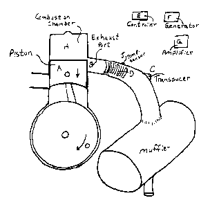
How it Works
Fig. 1
As the piston (A), moving down on its power stroke, approaches the
top of the exhaust port (B), a pulse/wave is fired from the transducer (C)
located down the exhaust pipe. This wave (D) moves rapidly up the pipe,
reflects off the piston and heads back down the pipe toward the muffler.
As the wave/pulse (D) moves away it creates a low pressure behind it at
the cylinderlpipe boundary(B) that may be considered a small vacuum.
This will help the gasses from the cylinder(H) move quickly into the
exhaust pipe.
This aid to accelerating the spent gasses plus the inertia of these
gasses will help pull the air/fuel through the transfer ports to the cylinder
in a shorter time frame. It has been observed that proper scavenging of
the cylinder can result in the air/fuel mixture being pulled into the exhaust
system for up to a distance of eighteen inches from the exhaust port (B).

CA 02220858 1998-O1-19
A Precise, Dynamic, Controlled (PDC) Exhaust / Intake
System
for the Internal Combustion Engine
Inventor: Lloyd W. Taylor
Raleigh, Nfld. Canada
Date: Dec. 16/97
Fig. 2
As the crank pin swings past bottom dead centre and the
piston (A) starts its way back up the cylinder (H), at the appropriate time,
another pulse (E) is fired. This will cause a reversal and compression of
the unburned air/fuel mixture leaving the cylinder (H). The mixture will
be effectively stuffed back into the cylinder just before the piston (A)
closes the exhaust port (B), providing a supercharging effect and quite a
boost in performance.
A11 of the above events are controlled by the onboard computer (E),
which gathers information from sensors such as the temperature sensor
(J), the Tachometer drive, etc.. Depending on need, the controller (E) will
direct the generator (F) to create the signal which is amplified by (G) and
sent to the transducer (C). Timing can be tied to a signal generated at the
flywheel as with the present ignition system , which is then advanced or
retarded as required.
The Advantage of this Invention
This system provides an opportunity to control breathing through the
internal combustion engine to a degree heretofore undreamed of. By using
inputs from various sensors such as exhaust temperature, RPM, etc., we
can calculate, using a small onboard computer, the precise timing of
pulses/waves to provide the desired effect. Then based on a pre-
determined map, a pulse/wave (single or multiple) can be introduced into
the exhaust/intake tract. This will provide optimum efficiencies from idle,
across the entire RPM range, to the maximum engine speed possible. No
longer will engineers or owners have to worry about waves/pulses
bouncing throughout the system causing peaks and valleys in the

CA 02220858 1998-O1-19
A Precise, Dynamic, Controlled (PDC) Exhaust / Intake
System
for the Internal Combustion Engine
Inventor: Lloyd W. Taylor
Raleigh, Nfld. Canada
Date: Dec. 16/97
power/torque curve and causing problems. The power/torque curve will
be flatter and therefore much higher at lower RPM . This is where most of
our efficiencies will be found. The latter point is significant since one of
the reasons why two-stroke motors have not been widely used in the
automotive world is their lack of low speed torque, low speed
driveability, poor fuel economy and excessive pollution caused by poor
combustion efficiency at speeds below the rpm for which the exhaust was
designed. All present applications of the two-stroke, from snowmobiles,
motorcycles and outboard motors will also benefit immensely from this
invention.
Claims
I do hereby make claim that the above system/device as sketched
and described
Applications
Although the above illustrations refer specifically to the exhaust of the
two-stroke engine, there are other applications where efficiencies may be
realized. As already suggested, the intake side of either a two-stroke or
four-stroke engine may benefit from such timed pulses. The exhaust side
of the four-stroke engine may also see improvement in efficiencies.
One more area which I see as an obvious beneficiary of this system
is with the Wankel or Rotary engine. Its design has some remarkable
similarities to that of the two-stroke engine. I feel that an exhaust/intake
system using the above controlled breathing system would provide
tremendous improvements in power, torque, fuel economy, and exhaust
emissions, as well as sound reduction.
END

Representative Drawing
A single figure which represents the drawing illustrating the invention.
Administrative Status

2024-08-01:As part of the Next Generation Patents (NGP) transition, the Canadian Patents Database (CPD) now contains a more detailed Event History, which replicates the Event Log of our new back-office solution.

Please note that "Inactive:" events refers to events no longer in use in our new back-office solution.

For a clearer understanding of the status of the application/patent presented on this page, the site Disclaimer , as well as the definitions for Patent , Event History , Maintenance Fee  and Payment History  should be consulted.

Event History

Description Date
Inactive: IPC from MCD 2006-03-12
Application Not Reinstated by Deadline 2003-12-08
Inactive: Dead - No reply to s.30(2) Rules requisition 2003-12-08
Inactive: Abandoned - No reply to s.30(2) Rules requisition 2002-12-09
Inactive: S.30(2) Rules - Examiner requisition 2002-06-07
Inactive: Cover page published 1999-10-06
Letter Sent 1999-08-17
Inactive: Correspondence - Formalities 1999-08-03
Inactive: Compliance - Formalities: Resp. Rec'd 1999-08-03
Request for Examination Received 1999-08-03
All Requirements for Examination Determined Compliant 1999-08-03
Request for Examination Requirements Determined Compliant 1999-08-03
Application Published (Open to Public Inspection) 1999-07-19
Inactive: Incomplete 1999-06-15
Inactive: IPC assigned 1998-03-21
Classification Modified 1998-03-21
Inactive: First IPC assigned 1998-03-21
Filing Requirements Determined Compliant 1998-02-04
Inactive: Filing certificate - No RFE (English) 1998-02-04
Application Received - Regular National 1998-02-03

Abandonment History

There is no abandonment history.

Maintenance Fee

The last payment was received on 2002-12-23

Note : If the full payment has not been received on or before the date indicated, a further fee may be required which may be one of the following

  • the reinstatement fee;
  • the late payment fee; or
  • additional fee to reverse deemed expiry.

Patent fees are adjusted on the 1st of January every year. The amounts above are the current amounts if received by December 31 of the current year.
Please refer to the CIPO Patent Fees web page to see all current fee amounts.

Fee History

Fee Type Anniversary Year Due Date Paid Date
Application fee - small 1998-01-19
Request for examination - small 1999-08-03
1999-08-03
MF (application, 2nd anniv.) - small 02 2000-01-19 1999-12-06
MF (application, 3rd anniv.) - small 03 2001-01-19 2000-12-01
MF (application, 4th anniv.) - small 04 2002-01-21 2002-01-15
MF (application, 5th anniv.) - small 05 2003-01-20 2002-12-23
Owners on Record

Note: Records showing the ownership history in alphabetical order.

Current Owners on Record
LLOYD TAYLOR
Past Owners on Record
None
Past Owners that do not appear in the "Owners on Record" listing will appear in other documentation within the application.
Documents

To view selected files, please enter reCAPTCHA code :


To view images, click a link in the Document Description column. To download the documents, select one or more checkboxes in the first column and then click the "Download Selected in PDF format (Zip Archive)" or the "Download Selected as Single PDF" button.

List of published and non-published patent-specific documents on the CPD .

If you have any difficulty accessing content, you can call the Client Service Centre at 1-866-997-1936 or send them an e-mail at CIPO Client Service Centre.


Document
Description 
Date
(yyyy-mm-dd) 
Number of pages   Size of Image (KB) 
Representative drawing 2002-06-06 1 7
Description 1998-01-18 5 235
Claims 1998-01-18 1 28
Abstract 1998-01-18 1 19
Drawings 1998-01-18 1 24
Filing Certificate (English) 1998-02-03 1 165
Acknowledgement of Request for Examination 1999-08-16 1 193
Notice: Maintenance Fee Reminder 1999-10-19 1 119
Notice: Maintenance Fee Reminder 2000-10-22 1 119
Notice: Maintenance Fee Reminder 2001-10-21 1 121
Notice: Maintenance Fee Reminder 2002-10-21 1 118
Courtesy - Abandonment Letter (R30(2)) 2003-02-16 1 167
Notice: Maintenance Fee Reminder 2003-10-20 1 114
Correspondence 1998-02-03 1 28
Correspondence 1999-06-07 1 15
Correspondence 1999-08-02 2 45
Fees 2002-12-22 1 69
Fees 1999-12-05 2 87
Fees 2002-01-14 1 22
Fees 2000-11-30 1 21