Language selection

Search

Patent 2221033 Summary

Third-party information liability

Some of the information on this Web page has been provided by external sources. The Government of Canada is not responsible for the accuracy, reliability or currency of the information supplied by external sources. Users wishing to rely upon this information should consult directly with the source of the information. Content provided by external sources is not subject to official languages, privacy and accessibility requirements.

Claims and Abstract availability

Any discrepancies in the text and image of the Claims and Abstract are due to differing posting times. Text of the Claims and Abstract are posted:

  • At the time the application is open to public inspection;
  • At the time of issue of the patent (grant).
(12) Patent Application: (11) CA 2221033
(54) English Title: A MIXING DEVICE FOR USE IN A BEVERAGE MACHINE
(54) French Title: DISPOSITIF MELANGEUR FAISANT PARTIE D'UNE MACHINE A BOISSON
Status: Deemed Abandoned and Beyond the Period of Reinstatement - Pending Response to Notice of Disregarded Communication
Bibliographic Data
(51) International Patent Classification (IPC):
  • B67D 07/74 (2010.01)
  • A47J 31/40 (2006.01)
(72) Inventors :
  • EVERS, LUCAS ALPHONSUS MARIA
(73) Owners :
  • KONINKLIJKE OLLAND GROEP B.V.
(71) Applicants :
  • KONINKLIJKE OLLAND GROEP B.V.
(74) Agent: AVENTUM IP LAW LLP
(74) Associate agent:
(45) Issued:
(22) Filed Date: 1997-11-13
(41) Open to Public Inspection: 1998-05-26
Availability of licence: N/A
Dedicated to the Public: N/A
(25) Language of filing: English

Patent Cooperation Treaty (PCT): No

(30) Application Priority Data:
Application No. Country/Territory Date
NO. 1004615 (Netherlands (Kingdom of the)) 1996-11-26

Abstracts

English Abstract


A mixing device for use in a beverage machine, comprising
a housing having inlet openings for ingredients to
be mixed in its upper part and having an outlet towards an
underlying mixing chamber having an outlet duct. The
mixing chamber has a closed front wall and a removable
rear wall on the opposite side. Adjacent the rear wall
there is provided a mixing disc which is carried by a
horizontal shaft that is rotatably supported between the
front and rear walls. The device is placed with its rear
side against a wall of the machine casing, behind which
there is a drive motor. The coupling between mixing disc
and drive shaft is formed by a magnetic field going
through said rear wall and generated between magnets that
are provided in said mixing disc and on the drive shaft
end respectively.


French Abstract

Dispositif mélangeur faisant partie d'une machine à boisson. Le dispositif se compose d'un boîtier ayant des ouvertures d'entrée pour les ingrédients à mélanger dans sa partie supérieure et d'une sortie débouchant dans une chambre de mélange sous-jacente ayant une conduite de sortie. La chambre de mélange comporte une paroi avant fermée et une paroi arrière amovible. Un disque mélangeur adjacent à la paroi arrière est monté sur un arbre horizontal de manière à tourner entre les parois avant et arrière. La paroi arrière du dispositif est située contre une paroi du boîtier de la machine, à l'arrière de laquelle se trouve un moteur d'entraînement. Le raccordement du disque mélangeur à l'arbre d'entraînement s'effectue au moyen d'un champ magnétique qui passe à travers la paroi arrière et qui est généré par des aimants se trouvant respectivement sur le disque mélangeur et sur l'extrémité de l'arbre d'entraînement.

Claims

Note: Claims are shown in the official language in which they were submitted.

I claim as my invention:
1. A mixing device for use in a beverage machine,
comprising a mixing beaker having inlet openings for liquid
and for material to be mixed therewith and having an
outlet towards a mixing chamber within a housing that is
positioned under said mixing beaker and has an outlet duct
at its bottom, said housing having a closed front wall and
a removable rear wall, while it is adapted to be detachably
mounted with its rear side to an upright casing wall
of the machine, a mixing member being mounted within the
chamber adjacent the rear side of the housing for rotation
about a lying axis, said mixing member being adapted to be
driven by an electric motor provided behind said casing
wall, wherein the disc-shaped mixing member is provided on
a support shaft that has its end rotatably supported in
seats provided on the inner side of the front wall and of
the rear wall respectively, the rearwardly facing end face
of the mixing disc carrying a set of permanent magnets,
which cooperate with a second set of magnets that are
provided, at corresponding locations, on the forwardly
directed end face of a coupling member on the shaft end of
the electric motor.
2. A mixing device according to claim 1, characterized
in that the coupling body is positioned closely adjacent
the casing wall, the latter being closed as well.
3. A mixing device according to claims 1-2, characterized
in that the circular rear wall slidingly fits in the
rear end portion of the housing, with an O-ring
therebetween.

Description

Note: Descriptions are shown in the official language in which they were submitted.


CA 02221033 1997-11-13
115P35CA
976040/B/lhe
A mixing device for use in a beverage machine.
BACKGROUND OF THE INVENTION
1. Field of the invention
This invention relates to the field of beverage
machines, more particularly to a mixing device for use in
such machines. A mixing device is envisaged which can be
readily detached from the machine for cleaning purposes
and which is of a type that is capable of producing an
additional foaming effect, as is desirable e.g. with some
types of coffee and chocolate drinks.
2. Description of the prior art
A mixing device capable of producing a foaming effect
and adapted to be readily detached for cleaning purposes
is disclosed in French patent specification 2,707,618.
More particularly this reference discloses a mixing
device for use in a beverage machine, comprising a mixing
beaker having inlet openings for liquid and for material
to be mixed therewith and having an outlet towards a
mixing chamber within a housing that is positioned under
said mixing beaker and has an outlet duct at its bottom,
said housing having a closed front wall and a removable
rear wall, while it is adapted to be detachably mounted
with its rear side to an upright casing wall of the machi-
ne, a mixing member being mounted within the chamber
adjacent the rear side of the housing for rotation about a
lying axis, said mixing member being adapted to be driven
by an electric motor provided behind said casing wall.
The shaft carrying the mixing device extends through
the removable rear wall and the upright casing wall and is
connected, behind the latter wall, to the drive shaft of
the electric motor.
In the document above referred to a number of purely
mechanical spigot joints are shown. Besides a particular
type of spigot joint is diagrammatically shown in fig. 3a

CA 02221033 1997-11-13
of the document, wherein a tapered shaft end of the elec-
tric motor engages a complementary conical recess in the
adjoining end of the shaft of the mixing member. It is
said in general terms that the engaging shaft ends are
kept engaged by magnetic force. It has not been indicated
and is neither obvious how this could be accomplished.
Advantageously the spigot joints disclosed in the
above mentioned document enable the mixing device to be
easily disconnected as a unit from the machine casing for
a subsequent transfer to a place where the device can be
disassembled and cleaned. It is a disadvantage, however,
that the shaft of the mixing member extends through the
rear wall of the mixing chamber, so that there is a risk
of leakage of liquid from the mixing chamber, with the
inherent risk for contamination around the shaft passing
through the upright casing wall. Anyway, in the drawings
of the documents the shaft of the mixing member is shown
extending through an annular member on the inner side of
the rear wall of the mixing chamber, which annular member
is likely to be meant as a sealing member (compare also
the mixing device according to US 4 185 927).
Furthermore European patent specification EP
0 285 210 discloses a mixing device for use with a beve-
rage machine, in which a shaft traversing the mixing
chamber rear wall is missing and whereby the device may
also be easily disassembled for cleaning purposes. With
this well-known device a mixing beaker is connected to a
cylindrical mixing chamber positioned therebelow, in which
a mixing member provided with one or more permanent mag-
nets is mounted for a reciprocating movement (vibration)
about the vertical axis of the mixing chamber under the
influence of a magnetic field that is produced by an
electromagnet positioned on the outer side. This well-
known device is not capable of producing a foaming effect.
Finally US 3,539,155 discloses an ultrafiltration
cell, wherein a vertical shaft, carrying at its lower free
end an agitation disc positioned close to the bottom wall

CA 02221033 1997-11-13
of a cylindrical housing, is provided at its upper end
with a horse shoe magnet that has its poles facing towards
the closed upper wall, said magnet cooperating with a
similar magnet on the shaft end of an electric motor
placed on top of said upper wall. The shaft is rotatably
supported by a bearing cage, that extends from the closed
upper wall downwardly to adjacent the agitation disc.
3. Obiects of the invention
It is an object to provide an improved foaming type
mixing device for use in a beverage machine.
It is another object to provide sich a mixing device
which is easily detachable as a unit from the casing of
the beverage machine so as to enable adequate cleaning of
the device at a place remote from the machine.
4. Summary of the invention
According this invention provides a mixing device for
use in a beverage machine, comprising a mixing beaker
having inlet openings for liquid and for material to be
mixed therewith and having an outlet towards a mixing
chamber within a housing that is positioned under said
mixing beaker and has an outlet duct at its bottom, said
housing having a closed front wall and a removable rear
wall, while it is adapted to be detachably mounted with
its rear side to an upright casing wall of the machine, a
mixing member being mounted within the chamber adjacent
the rear side of the housing for rotation about a lying
axis, said mixing member being adapted to be driven by an
electric motor provided behind said casing wall, wherein
the mixing member is provided on a support shaft that has
its ends rotatably supported in seats provided on the
inner side of the front wall and of the rear wall respec-
tively, the rearwardly facing end face of the mixing disc
carrying a set of permanent magnets, which cooperate with
a second set of magnets that are provided, at correspon-
ding locations, on the forwardly directed end face of a

~ CA 02221033 1997-11-13
coupling member on the shaft end of the electric motor.
Due to the connection between the shaft of the mixing
member and the motor shaft being accomplished in a purely
magnetic fashion - through a magnetic field produced by
two cooperating sets of magnets - the rear wall can be
completely closed. Moreover the inwardly extending sealing
structure with the well-known device is no longer existing
and is substituted by a simple bearing of the axiale type,
due to which the permanent magnets on the end face of the
mixing disc may be positioned rather close to the substan-
tially flat rear wall. Journalling of the shaft ends of
the mixing disc shaft in seats or bearings of the axial
type enables a quick disassembling and assembling of the
device.
5. Brief descri~tion of the drawinq
The invention will be hereinafter further explained
by way of example with reference to the drawing.
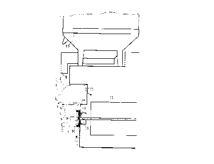
Fig. 1 is a diagrammatic fragmentary side elevation
of a beverage dispensing machine, provided with a mixing
device according to the invention;
Fig. 2 is a diagrammatic end view of the beverage
dispensing machine, as seen from the left in Fig. 1 and
Fig. 3 is a diagrammatic side view of the same machi-
ne, whereby the mixing device is removed from the remain-
der of the casing of the machine and the mixing device is
disassembled.
6. Detailed description of the invention
In the drawing 1 is the mixing device according to
the invention, which is composed of a mixing beaker 2,
that has a lower outlet duct 3 fitting in an upper inlet
duct 4 of a mixing chamber provided within a housing 5.
The mixing chamber within the housing 5 is delimited
on the front side by a closed wall 6, with a beverage
outlet duct 7 extending therefrom near the bottom. The
;~ing chamber is delimited on the opposite side by a

CA 02221033 1997-11-13
circular wall 8, having a circumferential flange with an
o-ring (not shown) provided therein for sealingly mounting
said wall into the rear open end of the housing 5 so as to
close the latter. An internal shoulder (not shown) in the
housing 5 may serve as a stop shoulder for the wall 8.
The front wall 6 and the removable rear wall 8 are
provided with axially directed seats 6a and 8a respecti-
vely, in which the ends of a shaft 9 may be rotatably
supported when placing the wall 8 into the housing. A
mixing disc 10 is provided on the shaft 9, having axially
and radially extending mixing ribs on its end face direc-
ted towards the front wall 10. Upon assembling the mixing
disc 10 is positioned closely adjacent the rear wall 8.
In the state ready for use the mixing device 1 is
mounted with the rear side of its housing 5 to a wall 11
of the casing of the beverage machine (see Fig. 1 and 2).
The mixing device 1 may be easily put in place by moving
it horizontally towards the housing 5 and allowing a
flange 15 of the housing 5 to engage a centring rib 3
projecting from the wall 11, while simultaneously causing
an inlet duct 14 provided on the beaker 2 for e.g. hot
water to slide into or over a corresponding connection
within the casing of the beverage machine.
Within the casing of the beverage machine, behind the
wall 11, an electric motor 15 is provided for driving the
mixing disc 8. The speed of the electric motor 15 is
10.000 - 14.000 r.p.m. The projecting shaft end of the
motor carries a coupling body 16, that extends with its
end face closely adjacent the inner side of the wall 11
and is provided with a set of permanent magnets 17 embed-
ded in said end face.
The mixing disc 10 is, at correspondingly oriented
locations, provided with permanent magnets 17a embedded in
the rearwardly facing end face of the disc. The magnetic
field between the permanent magnet sets 17 and 17a will
cause the individual magnets of the magnet set 17a to
align themselves directly opposite the magnets of the

CA 02221033 1997-11-13
magnet set 17, so that energizing of the motor 15 will
result in a torque being transferred to the mixing disc
10. Due to the two sets of permanent magnets 17 and 17a
respectively being embedded in a body of plastics material
and also the walls 8 and 11 being formed of plastics
material, an undisturbed field of force between the two
sets of permanent magnets 17 and 17a is secured.
- 19 is a supply container having in its bottom portion
a metering screw (not shown). In operation powdered mate-
rial, such as cacao powder or powdered coffee, is suppliedfrom the container, via an outlet duct 18 to the open
upper end of the beaker 2. Within the mixing chamber the
powdered material is mixed with liquid, such as hot water
or milk, supplied through the inlet 14, to produce the
desired, foamed beverage (coffee, chocolate).

Representative Drawing
A single figure which represents the drawing illustrating the invention.
Administrative Status

2024-08-01:As part of the Next Generation Patents (NGP) transition, the Canadian Patents Database (CPD) now contains a more detailed Event History, which replicates the Event Log of our new back-office solution.

Please note that "Inactive:" events refers to events no longer in use in our new back-office solution.

For a clearer understanding of the status of the application/patent presented on this page, the site Disclaimer , as well as the definitions for Patent , Event History , Maintenance Fee  and Payment History  should be consulted.

Event History

Description Date
Inactive: IPC expired 2022-01-01
Inactive: Adhoc Request Documented 2018-06-06
Revocation of Agent Requirements Determined Compliant 2018-05-18
Appointment of Agent Requirements Determined Compliant 2018-05-18
Inactive: IPC deactivated 2011-07-29
Inactive: First IPC derived 2010-02-01
Inactive: IPC from MCD 2010-02-01
Inactive: First IPC derived 2010-01-30
Inactive: IPC expired 2010-01-01
Inactive: IPC from MCD 2006-03-12
Application Not Reinstated by Deadline 2000-11-14
Time Limit for Reversal Expired 2000-11-14
Deemed Abandoned - Failure to Respond to Maintenance Fee Notice 1999-11-15
Application Published (Open to Public Inspection) 1998-05-26
Classification Modified 1998-02-25
Inactive: First IPC assigned 1998-02-25
Inactive: IPC assigned 1998-02-25
Inactive: Applicant deleted 1998-02-04
Letter Sent 1998-02-04
Application Received - Regular National 1998-02-04
Inactive: Filing certificate - No RFE (English) 1998-02-04

Abandonment History

Abandonment Date Reason Reinstatement Date
1999-11-15

Fee History

Fee Type Anniversary Year Due Date Paid Date
Registration of a document 1997-11-13
Application fee - standard 1997-11-13
Owners on Record

Note: Records showing the ownership history in alphabetical order.

Current Owners on Record
KONINKLIJKE OLLAND GROEP B.V.
Past Owners on Record
LUCAS ALPHONSUS MARIA EVERS
Past Owners that do not appear in the "Owners on Record" listing will appear in other documentation within the application.
Documents

To view selected files, please enter reCAPTCHA code :


To view images, click a link in the Document Description column. To download the documents, select one or more checkboxes in the first column and then click the "Download Selected in PDF format (Zip Archive)" or the "Download Selected as Single PDF" button.

List of published and non-published patent-specific documents on the CPD .

If you have any difficulty accessing content, you can call the Client Service Centre at 1-866-997-1936 or send them an e-mail at CIPO Client Service Centre.


Document
Description 
Date
(yyyy-mm-dd) 
Number of pages   Size of Image (KB) 
Abstract 1997-11-12 1 22
Claims 1997-11-12 1 40
Description 1997-11-12 6 272
Drawings 1997-11-12 2 28
Representative drawing 1998-05-31 1 5
Courtesy - Certificate of registration (related document(s)) 1998-02-03 1 118
Filing Certificate (English) 1998-02-03 1 165
Reminder of maintenance fee due 1999-07-13 1 112
Courtesy - Abandonment Letter (Maintenance Fee) 1999-12-12 1 184