Note: Descriptions are shown in the official language in which they were submitted.
CA 02221047 1997-11-13
SUCCESSIVE SCREW FEEDER DRIVER
BACKGROUND ART
Heretofore there have been proposed successive
screw feeder drivers capable of successively feeding
and driving screws into a plate such as, for example,
wooden plate or metallic plate to fix the plate to a
wall surface, a floor surface, or the like,
~ (hereinafter referred to as "a wall surface or the
like"). For example, a conventional successive screw
feeder driver of this type is shown in FIG. 5. In this
conventional successive screw feeder driver 51, a grip
CA 02221047 1997-11-13
handle 54 is formed and mounted in a generally ~-shape
below a screw driving mechanism body 53 which
incorporates a drive unit 52 therein, and a screw
driving rod-like bit 55, which corresponds to the screw-
driver as a commonly-used tool, is connected to the
drive unit 52 in the front portion of the screw driving
mechanism body 53. The bit 55 is rotated to drive
screws. This type is popular.
In the above conventional screw feeder driver
51, however J when the operator grasps the grip handle 54
and pushes the tip end of the bit 55 against the
surface of a plate or the like, if the screw driving
mechanism body 53 is pushed strongly against a wall
surface or the like during the work, a force of
rotating downward to the front (in the direction of
arrow A) is generated in the body 53, centered on the
screw portion being driven to the wall surface or the
like, because a pushing direction F of the operator's
hand and an axial direction of a virtual rotation line
CL of the bit 55 which drives the screw are vertically
spaced and separated from each other. Therefore, the
operator is required to not only push the tip end of
the bit in the screw driving direction continually but
also prevent the lower portion of the grip handle 54
CA 02221047 1997-11-13
from rotating downward to the front (in the arrow A
direction). Thus, the operator is required to apply an
extra force to the wrist, and there arises the problem
that when the work is continued over a long time, not
only the operator's palm which grasps the grip handle
but also his or her wrist is apt to become tired to
excess.
In the conventional successive screw feeder
driver 51, if the screw driving mechanism body 53 tilts
during the screw driving work, the screw will be driven
inclinedly relative to the surface of the plate or the
like, so that a part of the screw head is protruded
from the wall surface or the like and from the surface
of the plate. Thus, the appearance of the screw after
driving is deteriorated.
In the case of the grip handle 54 of a simple,
generally cylindrical shape used in the conventional
successive screw feeder driver 51, as shown in FIG. 6,
there occurs a clearance between the surface of the
grip handle 54 and the recess of the palm C. In other
words, the palm C does not fit the rear face of the grip
handle 54 perfectly. Accordingly, as the screw driving
work is continued over a long time, the operator
becomes tired in the palm and the grasping power is
- . CA 02221047 1997-11-13
deteriorated.
The present invention has been accomplished in
view of the above-mentioned problems and it is an
object of the invention to provide a successive screw
feeder driver wherein a screw driving direction of a
grip handle, namely a virtual rotation line of a bit,
and a pushing direction line of an opera~or's hand are
made substantially coincident with each other, a
housing which houses a drive unit therein is positioned
above the position where the virtual rotation line of
the bit is formed, and a supporting and pushing portion
of a grip handle is formed on the lower surface of the
housing, thereby permitting a pushing force of the palm
to be transmitted to the front of the bit axis exactly
and effectively at the time of driving a screw.
SUMMARY OF THE INVENTION
According to the present invention there is
provided a successive screw feeder driver comprising a
grip handle, a rotating mechanism provided on the upper
side of the grip handle, a screw driving bit attached
removably to the front portion of the rotating
mechanism, a reduction mechanism formed above the
rotating mechanism, a drive unit for rotating the bit,
CA 02221047 1997-11-13
the drive unit being connected to the reduction
mechanism so as to be positioned behind and above the
grip handle, a screw feed mechanism body which is
mounted to the front portion of the grip handle and
which is slidable in the longitudinal direction, with
the bit being inserted rotatably into the screw feed
mechanism body, a housing which houses the drive unit
therein, a supporting and pushing portion extending from
the upper portion of the rear end of the grip handle to
the lower surface of the housing beyond the position
where a virtual rotation line extending rearward of the
axis of the bit is formed, the supporting and pushing
portion being curved so that the palm portion of an
operator including the base portion of the operator's
thumb and forefinger can push the rear end of the
virtual rotation line when the operator grasps the grip
handle, and a screw feed mechanism provided in the screw
feed mechanism body for feeding screws successively to
a screw driving position for screw driving with the bit
in interlock with the longitudinal sliding motion of the
screw feed mechanism body which motion is synchronized
with the screw driving operation performed by the bit,
the screws being carried on a screw chain side by side
in a large number and in a belt-like arrangement.
CA 02221047 1997-11-13
The supporting and pushing portion of the grip
handle may be formed so as to be gently curved at the
upper portion of the grip handle and then projected
rearward. The grip handle may be formed below a
substantially centroid portion of the body of the screw
feeder driver, and its supporting and pushing portion
may be formed to have a thickness almost equal to the
thickness of the screw feed mechanism body.
According to the successive screw feeder driver
of the present invention, since the supporting and
pushing portion formed at an upper position of the rear
portion of the grip handle and including a virtual
rotation line extending rearward of the axis of the bit
can be pushed by the base portion of the operator's
thumb and forefinger and the operator's palm portion,
the line of action of the operator's hand which pushes
the screw driving mechanism body is positioned
substantially aligned with the bit axis, so that screws
can be pushed against a wall surface or the like and
driven always in a stable state.
Moreover, since the supporting and pushing
portion of the grip handle is projected rearward from
the upper portion of the grip handle contiguously~to a
curved surface which is gently curved from the lower to
. CA 02221047 1997-11-13
,
the upper portion of the grip handle, it is possible to
let the grip handle to fit the recess of the palm
closely without leaving any clearance, and hence the
operator does not become tired even when the screw
driving work is continued for a long time.
Further, since the supporting and pushing
portion of the grip handle has a thickness almost equal
to the thickness of the screw feed mechanism body, the
grip handle can be grasped firmly by the base portion
of the operator's thumb and forefinger. Besides, since
the drive unit which is the heaviest component in the
screw driving mechanism body can be borne just above
the operator's wrist which grasps the grip handle, there
can be obtained a stable grasping power and the
operator does not get tired even after using the screw
driving mechanism body for a long time.
According to the above construction, each screw
can be driven gradually into a wall surface or the like
by pushing the bit against the screw under rotation of
the drive unit while the front end of the screw feed
mechanism body with a screw chain loaded therein is
thrust against the wall surface or the like. Next, when
the front end of the screw feed mechanism body is
disengaged from the wall surface, the screw feed
CA 02221047 1997-11-13
mechanism body is pushed out to its original position.
At the same time, the screw feed mechanism operates to
feed the next screw on the screw chain to the screw
driving position. ~hus, the screw driving work can be
done successively by the same operations as above.
BRIEF DESCRIPTION OF THE DRAWINGS
Fig. 1 is a side view of a successive screw
feeder driver embodying the present invention, as
grasped by an operator;
Fig. 2 is a partial sectional side view showing
a drive unit and a reduction mechanism both used in the
successive screw feeder driver;
Fig. 3 is a plan view thereof;
Fig. 4 is a front view thereof;
Fig. 5 is a side view of a conventional
successive screw feeder driver as grasped by an
operator; and
Fig. 6 is a partial enlarged side view of a grip
handle of the conventional successive screw feeder
driver as grasped by an operator.
DESCRIPTION OF THE PREFERRED EMBODIMENTS
A successive screw feeder driver according to a
CA 02221047 1997-11-13
preferred embodiment of the present invention will be
described hereinunder with reference to the accompanying
drawings.
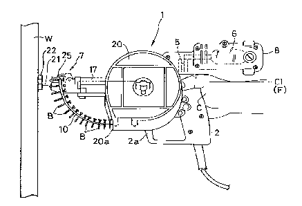
As shown in Figs. 1 to 4, which illustrate the
successive screw feeder driver, a bit 4 for driving
screws B is mounted removably in the front portion of
the successive screw feeder driver 1, through a
rotating me~hanism 3 disposed on the upper side of a
grip handle 2, and a reduction mechanism 5 is formed
above khe rotating mechanism 3. A drive unit 6 for
rotating the bit * through the reduction mechanlsm 5 is
connected to the reduction mechanism so as to be
positioned above the rear portion of the grip handle 2.
A screw feed mechanism body 7, which is slidable in the
longitudinal direction, is attached to the front
portion of the grip handle 2, and the bit 4 is inserted
rotatably into the screw feed mechanism body 7. The
drive unit is housed within a housing 8. Further, an
arcuate supporting and pushing portion 9 extended from
the upper portion of the rear end of the grip 2 to the
lower surface of the housing 8 extends beyond a virtual
rotation line CL extending rearward of the axis of the
bit 4. The supporting and pushing portion 9 is curved
so that when grasping the grip handle 2, an operator
CA 02221047 1997-11-13
can push the rear portion o~ the virtual rotation line
CL at his or her palm portion c including the base
portion of the thumb and the forefinger. A large number
of screws B~ B,~ are carried side by side in a belt-
like fashion on a screw chain 10, and the screw chain
10 is allowed to slide toward a feed mechanism portion
11 of the screw feed mechanism body 7 as each screw B is
driven by the bit 4. In this way the screws are fed
interlockedly to the screw driving position for driving
with the bit 4~
Along the lower surface of the housing 8 which
houses the drive unit 6 therein the rear portion of the
grip handle 2 extends rearward of the virtual rotation
line CL of the bit 4 to form the supporting and pushing
portion 9 which is curved~ When the operator grasps the
grip handle 2~ the base portion of the operator's thumb
and forefinger comes into abutment with the supporting
and pushing portion 9, whereby the successive screw
feeder driver 1 itself is supported at its centroid
portion and is thereby held stably~ Besides, it becomes
possible to perform the screw driving operation while
pushing the supporting and pushing portion 9 forward by
the palm C. Thus, a line F of the palm's pushing
action acting to push the successive screw feeder
--10--
CA 02221047 1997-11-13
driver 1 forward comes substantially into alignment
with the virtual rotation line CL of the bit 4. In
this way the screw driver feeder 1 is always held in a
stable posture and hence the bit 4, i.e., screw B can be
pushed against the wall surface or the like.
In this embodiment, a protective frame 2a is
integrally connected at its lower end portion to the
front side of the grip handle 2 to protect the hand's
back of the operator grasping the grip handle 2. These
components are positioned nearly centrally of the lower
portion of the successive screw feeder driver 1 to
support the driver 1 at two front and rear points and
thereby improve the stability thereof.
More specifically, the axis of the virtual
rotation line CL of the bit 4 and the pushing action
line F of the palm C acting to push the bit 4 forward
are substantially aligned with each other, so when the
operator pushes the successive screw feeder driver
strongly against the wall W, the pushing action line F
performs a straight forward push-out motion along the
vi,rtual rotation line CL. Consequently, it is possible
to avoid inconveniences of the conventional successive
screw feeder driver such as arcuate rotation of the grip
handle in the downward and forward direction A with the
CA 02221047 1997-11-13
front end portion of the bit as the rotation center
during screw driving and the resulting loss of
stability and an inclined driven posture of the screw
against the wall surface or the like. sesides, it is no
longer required for the operator to apply an extra
force to his or her palm C and wrist, thus eliminating
the fear of increased fatigue of the wrist even when
the screw driving work is continued for a long time.
According to this embodiment, as shown in Fig.
2, a gently rearwardly curved portion 12 is formed from
the lower to the upper portion of the grip handle 2.
The curved portion 12 is contiguous to the supporting
and pushing portion 9 of the grip handle 2 to provide
an integral form. This integral portion constitutes a
characteristic portion of the grip handle 2 in the
successive screw feeder driver 1. The supporting and
pushing portion 9 contiguous to the lower surface of
the housing 8 which houses the drive unit 6 such as, for
example, an electric motor or an air motor, as well as
the curved portion 12, permit the grip handle 2 to fit
the recess of the palm C of the operator grasping the
grip handle closely without leaving any clearance.
Therefore, even when the operator performs the screw
driving work over a long time while grasping the grip
-12-
CA 02221047 1997-11-13
handle 2 of the successive screw feeder driver 1, he or
she will not get tired in the hand.
As shown in Fig. 2, moreover, since the
supporting and pushing portion 9 of the grip handle 2
has a thickness almost equal to the thickness T of the
screw feed mechanism body 7, the grip handle 2 can be
grasped firmly by the base portion of the operator's
thumb and forefinger. Besides, the constituent portion
of the drive unit 6 which is the heaviest in the
successive screw feeder driver 1 can be borne just
above the operator's wrist which grasps the grip handle
2. Thus, the successive screw feeder driver 1 is
supported by the whole of the hand and can be grasped
firmly by using the grasping power of the palm c in an
auxiliary manner. That is, even a long-hour work does
not cause fatigue of the wrist.
As described above, in the successive screw
feeder driver 1 of this embodiment the reduction
mechanism 5 is interposed between the rotating
mechanism 3 for rotating the bit 4 and the drive unit 6
so that the number of revolutions of the bit 4 can be
changed as desired. A rotating shaft 14 supports
rotatably a gear device 13 which constitutes the
reduction mechanism 5, and it is disposed above a
--1~
CA 02221047 1997-11-13
rotary shaft 15 which is mounted coaxially behind the
bit 4. Further, the rotary shaft 14 is connected
through the gear device 13 to a drive shaft 16 of the
drive unit ~ which drive shaft is positioned above the
gear device. The shafts 14, 15 and 16 so arranged also
serve as factors for characteristically defining the
vertical position of the supporting and pushing portion
9 relative to the virtual rotation line CL of the bit 4
which portion 9 is formed upward at the rear portion of
the grip handle 2.
The screw feed mechanism body 7 is attached to
the front portion of the grip handle 2 through a pair
of guide poles 17,17 so as to be slidable
longitudinally. Between and in parallel with the
paired guide poles 17,17 is disposed the bit 4 for
driving the screws B. The bit 4 is connected removably
to a chuck 19 which is rotatable through a clutch 18 as
a constituent of the rotating mechanism 3. To a side
face of the grip handle 2 is attached removably a
magazine 20 which receives therein the screw chain 10 in
a rolled state. The screws B carried side by side on
the screw chain 10 can be fed successively out of a
take-out port 20a of the magazine 20.
It goes without saying that the mounting method
-14-
CA 02221047 1997-11-13
and posture of the magazine 20 for the successive screw
feeder driver 1, as well as the mounting direction of
the bit 4 relative to the virtual rotation line CL, are
not limited to the illustrated examples. For example,
the magazine 20 may be attached to the underside or a
side face of the successive screw feeder driver 1, or
design modifications may be made freely in relation to
the opening direction of the screw chain take-out port
20a.
The bit 4, which corresponds to the screw-driver
as a commonly-used tool, is constituted by a shaft of a
polygonal, namely hexagonal, sectional shape. At each
of both ends of the bit 4 is formed an engaging convex
portion 4a for engagement with an engaging groove, such
as + groove, formed in the head of each screw B, and a
groove (not shown) for engagement with the chuck 19
connected to the clutch 18 is formed circumferentially
of the bit 4 at a position near the engaging convex
portion 4a. The bit 4 can be reversed longitudinally
or replaced with a new one according to the degree of
wear of the engaging convex portions 4a formed at both
ends thereof.
~ he bit 4 is inserted rotatably into the screw
feed mechanism body 7, and a guide block 21 is attached
--1~
CA 02221047 1997-11-13
to the fron~ end of the screw feed mechanism body. The
front end of the guide block 21 is formed with an
abutment surface 22 for abutment with an object to be
screw-driven with screw B, the abutment surface 22
having an L-shaped groove 22a for guiding the screw B to
be driven. The screw feed mechanism body 7 is urged in
the push-out direction at all times by virtue of the
resilience of resilient members such as springs, mounted
within the guide poles 17,170 Nearly centrally of the
upper surface of the screw feed mechanism body 7 is
formed a screw feed groove 23 in the sliding and screw
driving direction so that the head of each screw B can
be pushed forward while rotating together with the bit
4.
The screw feed mechanism body 7 is provided with
a screw chain feed mechanism 24 for feeding the screws
B carried side by side on the screw chain 10 to the
screw driving position for screw driving with bit 4
successively in interlock with the screw driving
operation in the screw feed mechanism body 7. To guide
the screw chain 10 drawn out from the take-out port of
the magazin~e 20, a guide cover 25 is mounted on the
screw chain feed mechanism 24 in such a manner that it
can rise and fall above the screw driving direction and
CA 02221047 1997-11-13
becomes opposed to the groove for the screw head formed
in the screw feed mechanism body 7. The guide cover 25
can be largely opened forwardly upward to permit
removal of the screw chain 10.
The following description is now provided about
how to use the successive screw feeder driver of this
invention.
First, the head screw B carried on the screw
chain 10 which has been loaded into the screw feed
mechanism body 7 in the successive screw feeder driver 1
is brought to the screw driving position for screw
driving with bit 4, while the belt-like member
projecting sideways of the screw B is allowed to pass
into a guide path. At this position, the drive unit 6
is rotated while the abutment surface 22 of the guide
.
block 21 in the screw feed mechanism body 7 is pushed
against a plate or the like, and the clutch 18 is
engaged while the bit 4 is pushed against the screw B.
Then, the bit 4 further rotates to drive the screw B
gradually into the wall surface W. At the same time,
the screw feed mechanism body 7 (guide block 21) moves
back slowly toward the grip handle 2 and stops upon
abutment with the rear end portion of the guide block 21
which is integral with the screw feed mechanism body 7,
~ CA 02221047 1997-11-13
to release the clutch 18. Now, the screw driving work
for one screw B is over.
Next, the guide block 21 of the screw feed
mechanism body 7 is disengaged from the wall surface W,
whereupon the screw feed mechanism body 7 is pushed out
to its original position. At the same time, the screw
chain feed mechanism 24 operates to feed the next screw
B on the screw chain 10 to the screw driving position
and the same operations as above are repeated. In this
way the screw driving work can be done in a continuous
manner.
In the successive screw feeder driver 1, the
length of each of the screws B and the width of the
screw chain which carries the screws B side by side
thereon can be changed according to the thickness of
the plate or the wall W into which the screws are to be
driven. This can be done as necessary by changing the
position of a guide (not shown) formed in the screw
feed mechanism body 7.
According to the successive screw feeder driver
constructed as above, in performing the screw driving
work continuously, if only the operator pushes the
supporting and pushing portion formed at the rear
portion of the grip handle with the base portion of his
-18-
CA 02221047 1997-11-13
or her thumb and forefinger or with the palm portion,
the force action line of the pushing hand for the
successive screw feeder driver becomes substantially
aligned with the virtual rotation line of the bit and
hence the screw driving work for a wall surface or the
like can be done always in a stable state.
Moreover, since a curved portion is formed contiguously
to the supporting and pushing portion, the operator's
grasping state for the grip handle can be modified into
a state suitable for the screw driving work so that the
palm can fit the grip handle closely without any
clearance, thus making an increase of fatigue difficult
even when the successive screw feeder driver is used
for a long time. Further, even in the case where the
successive screw feeder driver is supported
horizontally, since the grip handle is formed
substantially at a centroid position and the virtual
rotation line of the bit is formed nearly down to the
palm position, the feeling of stability in the support
is enhanced, thus contributing to the decrease of
fatigue feeling and making the successive screw feeder
driver suitable for a long-time screw driving work.
Thus, extremely outstanding effects are attained by the
present invention.
--19--
CA 02221047 1997-11-13
POSSIBILITY OF ~XPLORATION IN INDUSTRY
According to the successive screw feeder driver,
screws can be driven continuously for fixing a plate
such as wooden plate or metallic plate to a wall
surface, a floor surface, or the like, the screw
driving dir~ection of the grip handle, or the virtual
rotation line of the bit axis, and the line of pushing
direction of the operator's hand are made nearly
coincident with each other, the housing which houses
the drive unit therein is positioned above the position
where the virtual rotation line of the bit is formed,
and the supporting and pushing portion of the grip
handle is formed along the underside of the housing,
whereby the pushing force of the palm can be transmitted
to the front portion of the bit axis exactly and
effectively at the time of driving screws.
-20-